2006 SUZUKI SX4 sensor
[x] Cancel search: sensorPage 996 of 1556

Downloaded from www.Manualslib.com manuals search engine 7B-56 Air Conditioning System: Automatic Type
Scan Tool Data Definitions
TEMP CONT SWITCH: (Temperature control selector
position, Max Cool, °C / °F, Max Hot): This
parameter indicates the selected position of
temperature control selector.
CABIN TEMPERATURE: (In-car temperature, °C, °F):
This parameter indicates the in-car temperature
detected by inside air temperature sensor.OUTSIDE AIR TEMP (Outside air temperature, °C,
°F): This parameter indicates the outside air
temperature detected by outside air temperature
sensor.
EVAPORATOR TEMP (Evaporator temperature, °C,
°F): This parameter indicates the temperature of air
passed through evaporator.
COOLANT TEMP (Engine Coolant Temperature °C,
°F): This parameter indicates the engine coolant
temperature detected by engine coolant temperature
sensor. �) COOLANT TEMP
Ignition switch turned ONEngine coolant temperature is
displayed
�) SUN LOAD Reference value depends on the situation 0 W/m
2 – 1988 W/m2
�)MODE CONT
SWITCHIgnition switch turned ON and air flow selector at
AUTO positionAUTO (Selected position of air flow
selector is displayed)
�) FAN CONT SWITCHIgnition switch turned ON and blower speed selector
at AUTO positionAUTO (Selected position of blower
speed selector is displayed)
�) FAN DESIRED VOLTIgnition switch turned ON and blower speed selector
at HighApprox. 12.0 V
Ignition switch turned ON and blower speed selector
at LowApprox. 4.0 V
�) AIR MIX POS SENIgnition switch turned ON and temperature selector
at maximum cool positionApprox. 0.5 V
Ignition switch turned ON and temperature selector
at maximum hot positionApprox. 4.5 V
�)MODE POS SENSORIgnition switch turned ON and air flow selector at
DEF positionApprox. 4.5 V
Ignition switch turned ON and air flow selector at
VENT positionApprox. 0.5 V
�) A/C CONT SIGA/C switch turned ON, blower speed selector at other
than OFF position with engine runningON
A/C switch turned OFF with engine running OFF
�) BLOWER LOAD SIGIgnition switch turned ON, blower speed selector at
other than OFF positionON
Ignition switch turned ON, blower speed selector at
OFF positionOFF
�) AIR INTAKE MODEIgnition switch turned ON and air intake selector at
fresh air (FRE) positionFRE
Ignition switch turned ON and air intake selector at
recirculation air (REC) positionREC
Ignition switch turned ON, air flow selector and
blower speed selector at AUTO positionAUTO
�) REFRIGERANT
PRESSUREA/C ON (A/C is operating) with engine running at
ambient temperature 30 °C (86 °F)1130 – 1560 kPa (For details, refer to
pressure of high pressure gauge
under “A/C System Performance
Inspection”)
A/C OFF (A/C is not operating) with engine running
at ambient temperature 30 °C (86 °F) and engine
coolant temperature 90 °C (194 °F) – 100 °C (212
°F)600 – 1000 kPa after longer than 10
minute for A/C switch turned off
�) A/C COMP CLUTCHA/C switch turned ON, blower speed selector at other
than OFF position with engine runningON
A/C switch turned OFF with engine running OFF
�) VEHICLE SPEED At stop with ignition switch turned ON 0 km/h (0 mph)
�) ENGINE TYPE Ignition switch turned ON Engine type is displayed.
�) METER SPEC Ignition switch turned ONCombination meter spec is displayed. Scan Tool Data ConditionNormal Condition / Reference
Va l u e
Page 997 of 1556

Downloaded from www.Manualslib.com manuals search engine Air Conditioning System: Automatic Type 7B-57
SUN LOAD (W/m2): This parameter indicates the
amount of sunlight detected by sunload sensor.
MODE CONT SWITCH (Air flow selector position,
AUTO, FACE, B/L, FOOT, D/F, DEF): This
parameter indicates the selected position of air flow
selector.
FAN CONT SWITCH (Blower speed selector, AUTO,
OFF, 1st – 8th): This parameter indicates the
selected position of blower speed selector.
FAN DESIRE VOLT (Fan desired voltage, V): This
parameter indicates the consumption voltage of
blower motor.
AIR MIX POS SENSOR (Temperature control
actuator position sensor, V): This parameter
indicates the input signal from position sensor in
temperature control actuator.
MODE POS SENSOR (Air flow control actuator
position sensor, V): This parameter indicates the
input signal from position sensor in air flow control
actuator.
A/C CONT SIG (A/C control signal, ON, OFF): This
parameter indicates the state of A/C switch.BLOWER LOAD SIG (Blower fan load signal, ON,
OFF): ON: Position of blower speed selector is 1st
position or more.
OFF: Position of blower speed selector is OFF
position.
AIR INTAKE MODE (Air intake selector position,
AUTO, FRE, REC): This parameter indicates the
selected position of air intake selector.
REFRIGERANT PRESSURE (A/C refrigerant absolute
pressure, kPa): This parameter indicates the A/C
refrigerant absolute pressure calculated by ECM
A/C COMP CLUCH (A/C compressor magnet clutch,
ON, OFF): This parameter indicates the state of the
A/C compressor magnet clutch.
VEHICLE SPEED (km/h, mph): This parameter
indicates the vehicle speed calculated by ECM.
ENGINE TYPE (Engine type signal, J20, M16 or
M15): This parameter indicates the engine type
signal transmitted by ECM.
METER SPEC (Combination meter spec signal, EU,
UK, US, Canada, DOM): This parameter indicates
the combination meter spec signal transmitted by
combination meter.
Visual InspectionS6RW0D7224009
Check visually the following parts and systems.
DTC B1502: Inside Air Temperature Sensor Circuit MalfunctionS6RW0D7224010
Wiring DiagramInspection item Correction
• Refrigerant leakage and amount
• A/C pipe or hose disconnection,
looseness and
deterioration
• A/C compressor drive belt looseness and damageRefer to “Compressor Drive Belt Inspection
and Adjustment”.
• Battery fluid level and corrosion
of terminal
• Connectors of electric wire harness disconnection and
friction
• Fuses burning
• Parts installation and damage
• Other parts that can be checked visually
5V
G20
1 2 3 4 5 6 7 8 9 10 11 12 13 14
15 16 17 18 19 20 21 24 23 22 25 26 27 28 29 30
ORNORNPNK/BLKG20-10
21
3 [S]
[G]
G20-24
I7RW01722004-01
[S]: Inside air temperature sensor signal circuit 1. HVAC control module 3. To other sensors
[G]: Inside air temperature sensor ground circuit 2. Inside air temperature sensor
Page 998 of 1556

Downloaded from www.Manualslib.com manuals search engine 7B-58 Air Conditioning System: Automatic Type
DTC Detecting Condition and Trouble Area
DTC Troubleshooting
NOTE
When DTC B1503, B1504, B1511 and B1512 are indicated together, it is possible that sensor ground
circuit is open.
DTC Detecting Condition Trouble Area
Inside air temperature sensor signal voltage is higher than or lower than
specified value for specified time continuously.• Inside air temperature sensor circuit
• Inside air temperature sensor
• HVAC control module
Step Action Yes No
1Was “Air Conditioning System Check” performed?Go to Step 2. Go to “Air Conditioning
System Check”.
2Wire harness check
1) Turn ignition switch to OFF position.
2) Disconnect connectors from inside air temperature
sensor and HVAC control module.
3) Check for proper connection to each signal circuit
terminal and ground circuit terminal of inside air
temperature sensor and HVAC control module
connectors.
4) If OK, check that inside air temperature sensor circuit is
as follows.
• Wiring harness resistance of each inside air
temperature sensor signal circuit and ground circuit is
less than 3 Ω
• Insulation resistance between inside air temperature
sensor signal circuit and vehicle body ground is
infinity
• Circuit voltage of each inside air temperature sensor
signal circuit and ground circuit is 0 – 1 V with ignition
switch turned ON
Are they in good condition?Go to Step 3. Inside air temperature
sensor signal circuit
and/or ground circuit are
open, short or high
resistance.
3Inside air temperature sensor reference voltage check
1) Connect connector to HVAC control module with ignition
switch turned OFF.
2) Turn ignition switch to ON position.
3) Measure voltage between signal terminal and ground
terminal of inside air temperature sensor connector.
Is voltage 4.5 – 5.5 V?Go to Step 4. Substitute a known-
good HVAC control
module and recheck.
4Inside air temperature sensor check
1) Check inside air temperature sensor for performance
referring to “Inside Air Temperature Sensor Inspection”.
Is it in good condition?Substitute a known-
good HVAC control
module and recheck.Replace inside air
temperature sensor.
Page 999 of 1556

Downloaded from www.Manualslib.com manuals search engine Air Conditioning System: Automatic Type 7B-59
DTC B1503: Evaporator Temperature Sensor Circuit MalfunctionS6RW0D7224011
Wiring Diagram
DTC Detecting Condition and Trouble Area
DTC Troubleshooting
NOTE
When DTC B1502, B1504, B1511 and B1512 are indicated together, it is possible that sensor ground
circuit is open.
5V
G20
1 2 3 4 5 6 7 8 9 10 11 12 13 14
15 16 17 18 19 20 21 24 23 22 25 26 27 28 29 30
ORNORNWHT/BLKG20-9G20-24
[S]
[G] 2
31
I7RW01722005-01
[S]: Evaporator temperature sensor signal circuit 1. HVAC control module 3. To other sensors
[G]: Evaporator temperature sensor ground circuit 2. Evaporator temperature sensor
DTC Detecting Condition Trouble Area
Evaporator temperature sensor signal voltage is higher than or lower than
specified value for specified time continuously.• Evaporator temperature sensor
circuit
• Evaporator temperature sensor
• HVAC control module
Step Action Yes No
1Was “Air Conditioning System Check” performed?Go to Step 2. Go to “Air Conditioning
System Check”.
2Wire harness check
1) Turn ignition switch to OFF position.
2) Disconnect connectors from evaporator temperature
sensor and HVAC control module.
3) Check for proper connection to each signal circuit
terminal and ground circuit terminal of evaporator
temperature sensor and HVAC control module
connectors.
4) If OK, check that evaporator temperature sensor circuit
is as follows.
• Wiring harness resistance of each evaporator
temperature sensor signal circuit and ground circuit is
less than 3 Ω
• Insulation resistance between evaporator temperature
sensor signal circuit and vehicle body ground is
Infinity
• Circuit voltage of each evaporator temperature sensor
signal circuit and ground circuit is 0 - 1 V with ignition
switch turned ON
Are they good condition?Go to Step 3. Evaporator temperature
sensor signal circuit
and/or ground circuit are
open, short or high
resistance.
Page 1000 of 1556

Downloaded from www.Manualslib.com manuals search engine 7B-60 Air Conditioning System: Automatic Type
DTC B1504: Sunload Sensor Circuit MalfunctionS6RW0D7224012
Wiring Diagram
DTC Detecting Condition and Trouble Area
NOTE
When DTC B1502, B1503, B1511 and B1512 are indicated together, it is possible that sensor ground
circuit is open.
3Evaporator temperature sensor reference voltage check
1) Connect connector to HVAC control module with ignition
switch turned OFF.
2) Turn ignition switch to ON position.
3) Measure voltage between signal terminal and ground
terminal of evaporator temperature sensor connector.
Is voltage 4.5 – 5.5 V?Go to Step 4. Substitute a known-
good HVAC control
module and recheck.
4Evaporator temperature sensor check
1) Check evaporator temperature sensor for performance
referring to “Evaporator Temperature Sensor
Inspection”.
Is it in good condition?Substitute a known-
good HVAC control
module and recheck.Replace evaporator
temperature sensor. Step Action Yes No
G20
1 2 3 4 5 6 7 8 9 10 11 12 13 14
15 16 17 18 19 20 21 24 23 22 25 26 27 28 29 30
PNK
ORNORN
G20-25
G20-24
2
[S]
[G]15V
3
I7RW01722006-01
[S]: Sunload sensor signal circuit 1. HVAC control module 3. To other sensors
[G]: Sunload sensor ground circuit 2. Sunload sensor
DTC Detecting Condition Trouble Area
• Sunload sensor signal voltage is higher than or lower than specified value
for specified time continuously.
• Without sunlight• Sunload sensor circuit
• Sunload sensor
• HVAC control module
Page 1001 of 1556

Downloaded from www.Manualslib.com manuals search engine Air Conditioning System: Automatic Type 7B-61
DTC Troubleshooting
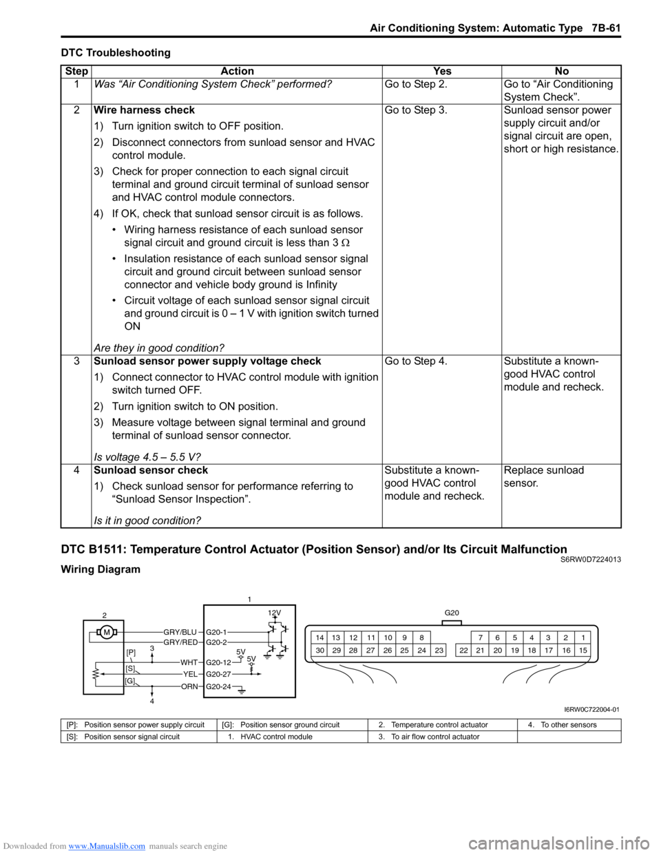
DTC B1511: Temperature Control Actuator (Position Sensor) and/or Its Circuit MalfunctionS6RW0D7224013
Wiring DiagramStep Action Yes No
1Was “Air Conditioning System Check” performed?Go to Step 2. Go to “Air Conditioning
System Check”.
2Wire harness check
1) Turn ignition switch to OFF position.
2) Disconnect connectors from sunload sensor and HVAC
control module.
3) Check for proper connection to each signal circuit
terminal and ground circuit terminal of sunload sensor
and HVAC control module connectors.
4) If OK, check that sunload sensor circuit is as follows.
• Wiring harness resistance of each sunload sensor
signal circuit and ground circuit is less than 3 Ω
• Insulation resistance of each sunload sensor signal
circuit and ground circuit between sunload sensor
connector and vehicle body ground is Infinity
• Circuit voltage of each sunload sensor signal circuit
and ground circuit is 0 – 1 V with ignition switch turned
ON
Are they in good condition?Go to Step 3. Sunload sensor power
supply circuit and/or
signal circuit are open,
short or high resistance.
3Sunload sensor power supply voltage check
1) Connect connector to HVAC control module with ignition
switch turned OFF.
2) Turn ignition switch to ON position.
3) Measure voltage between signal terminal and ground
terminal of sunload sensor connector.
Is voltage 4.5 – 5.5 V?Go to Step 4. Substitute a known-
good HVAC control
module and recheck.
4Sunload sensor check
1) Check sunload sensor for performance referring to
“Sunload Sensor Inspection”.
Is it in good condition?Substitute a known-
good HVAC control
module and recheck.Replace sunload
sensor.
G20
1 2 3 4 5 6 7 8 9 10 11 12 13 14
15 16 17 18 19 20 21 24 23 22 25 26 27 28 29 30
GRY/BLUGRY/RED
5V5V
12V
ORN
WHT
YEL
G20-12
G20-27
G20-24
G20-1G20-2
2
[P]
[S]3
4
[G]
1
I6RW0C722004-01
[P]: Position sensor power supply circuit [G]: Position sensor ground circuit 2. Temperature control actuator 4. To other sensors
[S]: Position sensor signal circuit 1. HVAC control module 3. To air flow control actuator
Page 1002 of 1556

Downloaded from www.Manualslib.com manuals search engine 7B-62 Air Conditioning System: Automatic Type
DTC Detecting Condition and Trouble Area
DTC Troubleshooting
NOTE
• When DTC B1502, B1503, B1504 and B1512 are indicated together, it is possible that sensor ground
circuit is open.
• When DTC B1512 is indicated together, it is possible that position sensor power supply circuit is
open.
DTC Detecting Condition Trouble Area
Temperature control actuator position sensor signal voltage is higher than or
lower than specified value for specified time continuously.• Temperature control actuator circuit
• Temperature control actuator
• HVAC control module
Step Action Yes No
1Was “Air Conditioning System Check” performed?Go to Step 2. Go to “Air Conditioning
System Check”.
2Wire harness check
1) Turn ignition switch to OFF position.
2) Disconnect connectors from temperature control
actuator and HVAC control module.
3) Check for proper connection to position sensor power
supply, signal and ground circuit terminals of
temperature control actuator and HVAC control module
connectors.
4) If OK, check that position sensor of temperature control
actuator circuit is as follows.
• Wiring harness resistance of each position sensor
power supply, signal and ground circuit is less than 3
Ω
• Insulation resistance of each position sensor power
supply, signal and ground circuit is infinity between
temperature control actuator connector and vehicle
body ground
• Circuit voltage of each position sensor power supply,
signal and ground circuit is 0 - 1 V with ignition switch
turned ON
Are they in good condition?Go to Step 3. Position sensor power
supply, signal circuit
and/or ground circuit are
open, short or high
resistance.
3Position sensor of temperature control actuator power
supply voltage check
1) Connect connector to HVAC control module.
2) Turn ignition switch to ON position.
3) Measure voltage between.
• Position sensor power supply terminal and position
sensor ground terminal of temperature control
actuator connector
• Position sensor signal terminal and position sensor
ground terminal of temperature control actuator
connector
Is voltage 4.5 – 5.5 V?Go to Step 4. Go to Step 5.
Page 1003 of 1556

Downloaded from www.Manualslib.com manuals search engine Air Conditioning System: Automatic Type 7B-63
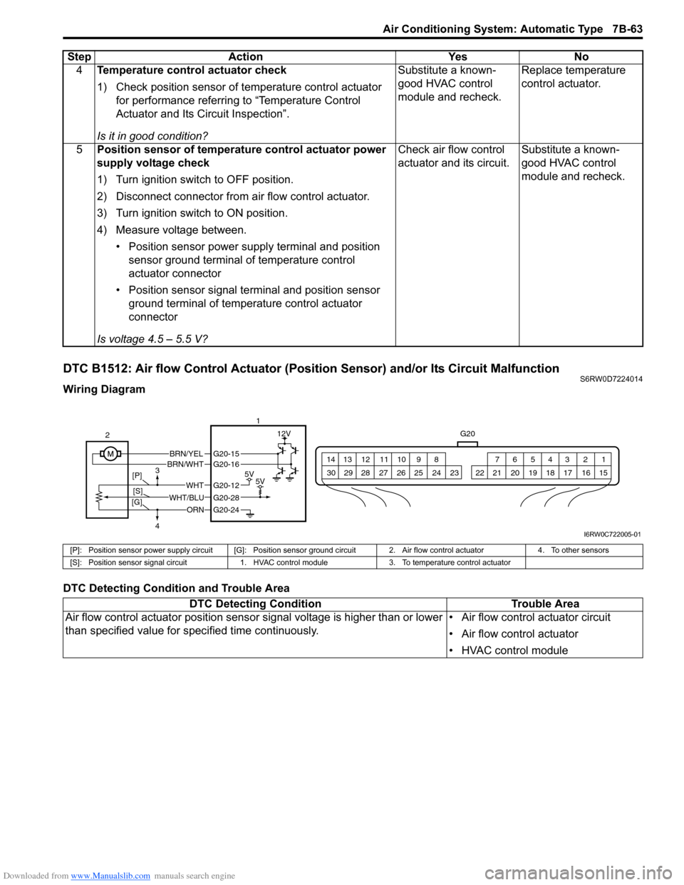
DTC B1512: Air flow Control Actuator (Position Sensor) and/or Its Circuit MalfunctionS6RW0D7224014
Wiring Diagram
DTC Detecting Condition and Trouble Area4Temperature control actuator check
1) Check position sensor of temperature control actuator
for performance referring to “Temperature Control
Actuator and Its Circuit Inspection”.
Is it in good condition?Substitute a known-
good HVAC control
module and recheck.Replace temperature
control actuator.
5Position sensor of temperature control actuator power
supply voltage check
1) Turn ignition switch to OFF position.
2) Disconnect connector from air flow control actuator.
3) Turn ignition switch to ON position.
4) Measure voltage between.
• Position sensor power supply terminal and position
sensor ground terminal of temperature control
actuator connector
• Position sensor signal terminal and position sensor
ground terminal of temperature control actuator
connector
Is voltage 4.5 – 5.5 V?Check air flow control
actuator and its circuit.Substitute a known-
good HVAC control
module and recheck. Step Action Yes No
G20
1 2 3 4 5 6 7 8 9 10 11 12 13 14
15 16 17 18 19 20 21 24 23 22 25 26 27 28 29 30
BRN/YELBRN/WHT
5V5V
12V
ORN
WHTG20-12
G20-28
G20-24
G20-15G20-16
WHT/BLU 2
3
4
[P]
[G][S]1
I6RW0C722005-01
[P]: Position sensor power supply circuit [G]: Position sensor ground circuit 2. Air flow control actuator 4. To other sensors
[S]: Position sensor signal circuit 1. HVAC control module 3. To temperature control actuator
DTC Detecting Condition Trouble Area
Air flow control actuator position sensor signal voltage is higher than or lower
than specified value for specified time continuously.• Air flow control actuator circuit
• Air flow control actuator
• HVAC control module