2006 SUZUKI SX4 200
[x] Cancel search: 200Page 1323 of 1556
Downloaded from www.Manualslib.com manuals search engine Lighting Systems: 9B-4
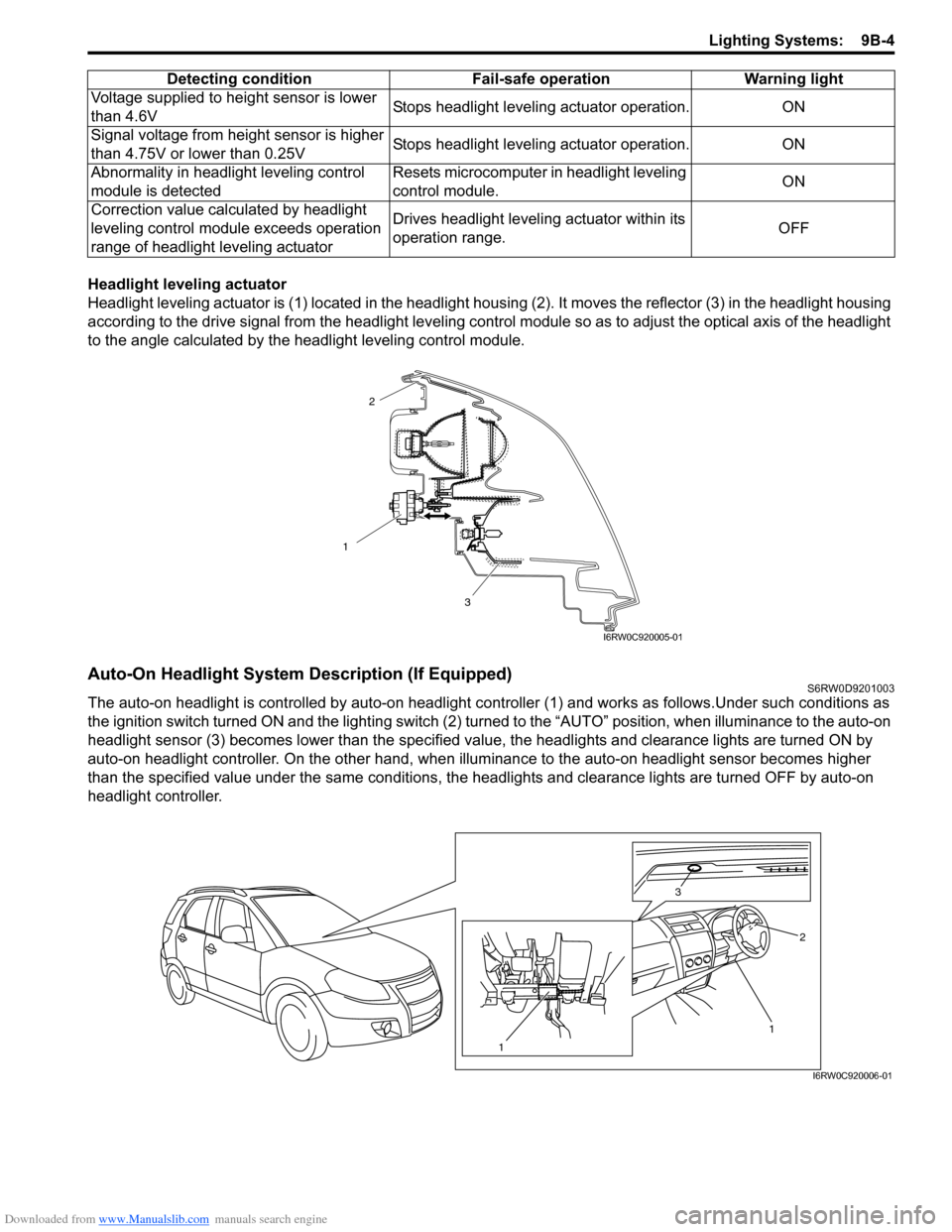
Headlight leveling actuator
Headlight leveling actuator is (1) located in the headlight housing (2). It moves the reflector (3) in the headlight housing
according to the drive signal from the headlight leveling control module so as to adjust the optical axis of the headlight
to the angle calculated by the headlight leveling control module.
Auto-On Headlight System Description (If Equipped)S6RW0D9201003
The auto-on headlight is controlled by auto-on headlight controller (1) and works as follows.Under such conditions as
the ignition switch turned ON and the lighting switch (2) turned to the “AUTO” position, when illuminance to the auto-on
headlight sensor (3) becomes lower than the specified value, the headlights and clearance lights are turned ON by
auto-on headlight controller. On the other hand, when illuminance to the auto-on headlight sensor becomes higher
than the specified value under the same conditions, the headlights and clearance lights are turned OFF by auto-on
headlight controller.Voltage supplied to height sensor is lower
than 4.6VStops headlight leveling actuator operation. ON
Signal voltage from height sensor is higher
than 4.75V or lower than 0.25VStops headlight leveling actuator operation. ON
Abnormality in headlight leveling control
module is detectedResets microcomputer in headlight leveling
control module.ON
Correction value calculated by headlight
leveling control module exceeds operation
range of headlight leveling actuatorDrives headlight leveling actuator within its
operation range.OFF Detecting condition Fail-safe operation Warning light
1
3
2
I6RW0C920005-01
1 3
2
1
I6RW0C920006-01
Page 1324 of 1556
Downloaded from www.Manualslib.com manuals search engine 9B-5 Lighting Systems:
Schematic and Routing Diagram
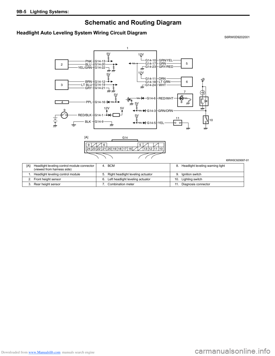
Headlight Auto Leveling System Wiring Circuit DiagramS6RW0D9202001
G14-12G14-19G14-21
G14-10
G14-23
+B
5V
5V
GRN/YEL
GRY/RED
BLK
G14-112V
BRNLT BLUGRY
RED/BLK
3
G14-13G14-20G14-22
5V
PNKBLUYEL/GRN2
45
9
10 11 1
5V
5V
12V
G14-16
G14-3
PPL
GRN/ORN
5V
G14-5YEL
G14-17GRN
G14-11
G14-24
ORN
WHT6 12VG14-18LT GRN
7
8
G14-6
G14-9
RED/WHT
G14
10 11 12 13 16 17 18 19 205 6 9
21 22 23 24
[A]
I6RW0C920007-01
[A]: Headlight leveling control module connector
(viewed from harness side)4. BCM 8. Headlight leveling warning light
1. Headlight leveling control module 5. Right headlight leveling actuator 9. Ignition switch
2. Front height sensor 6. Left headlight leveling actuator 10. Lighting switch
3. Rear height sensor 7. Combination meter 11. Diagnosis connector
Page 1325 of 1556
Downloaded from www.Manualslib.com manuals search engine Lighting Systems: 9B-6
Component Location
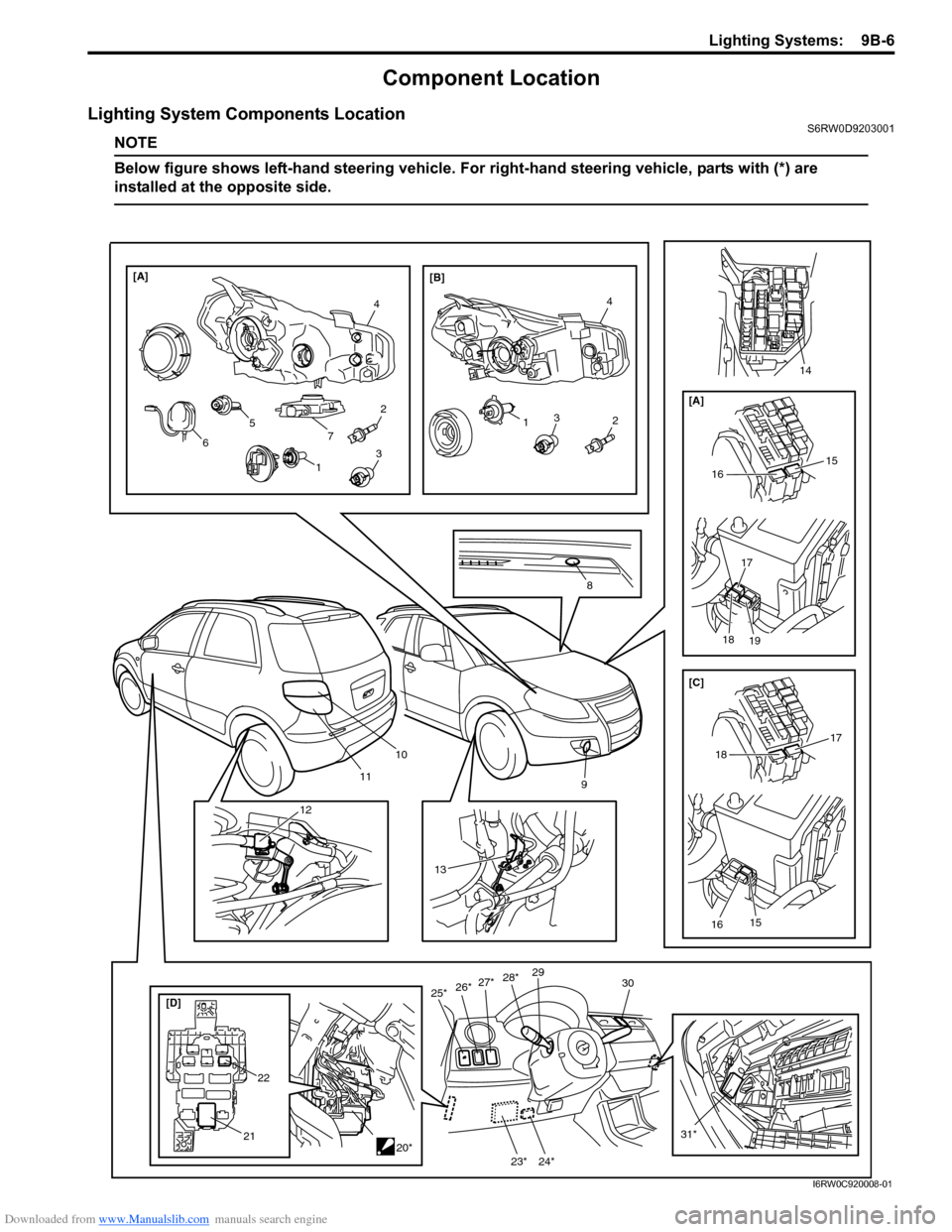
Lighting System Components LocationS6RW0D9203001
NOTE
Below figure shows left-hand steering vehicle. For right-hand steering vehicle, parts with (*) are
installed at the opposite side.
10
119
[D]25*30
21
27*26*29
31*20*
13
4
2
4
[A]
[B]
8
132
7 5
6
12
13
22
28*
15
16
[A]
17
18
19
15
16
17
18 [C]
14
23* 24*
I6RW0C920008-01
Page 1326 of 1556
Downloaded from www.Manualslib.com manuals search engine 9B-7 Lighting Systems:
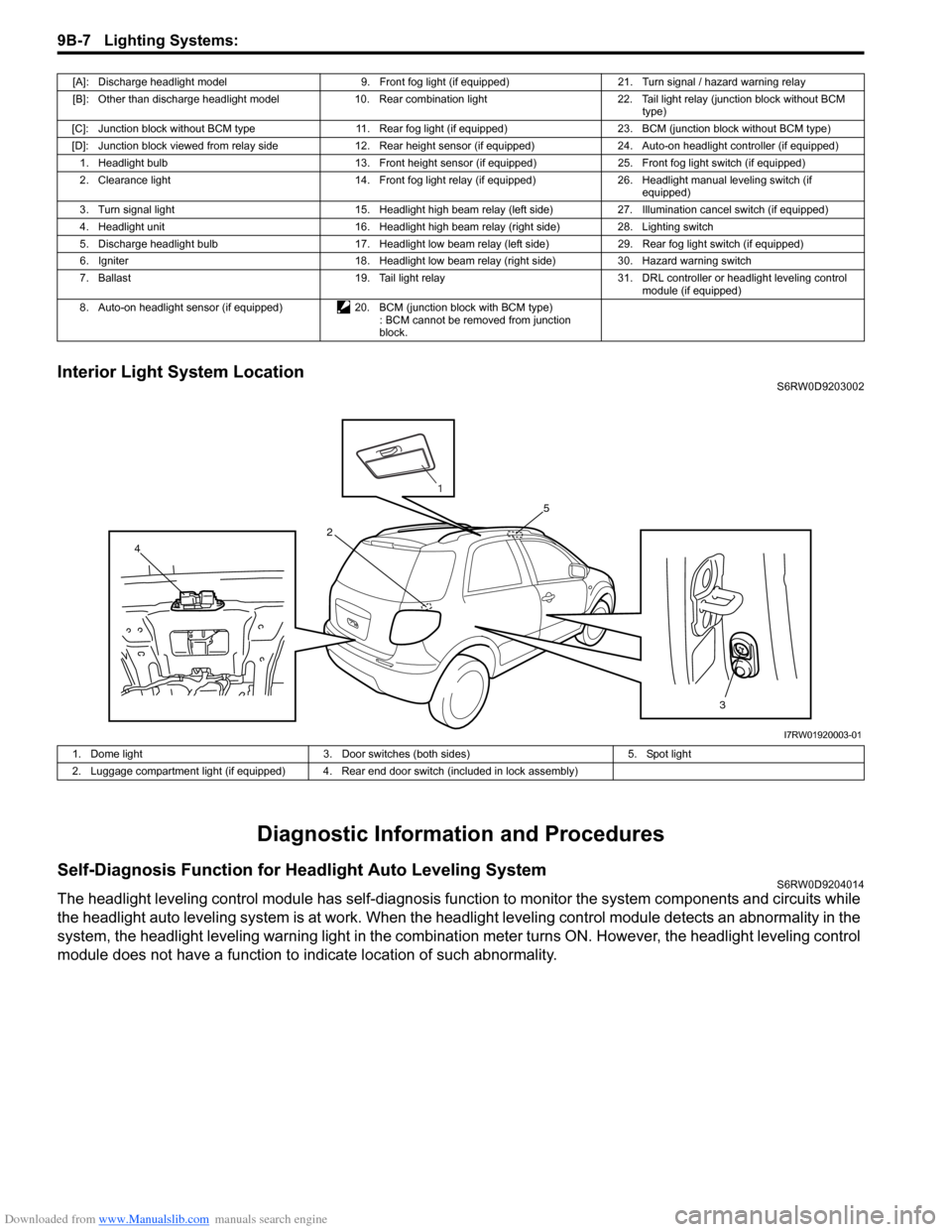
Interior Light System LocationS6RW0D9203002
Diagnostic Information and Procedures
Self-Diagnosis Function for Headlight Auto Leveling SystemS6RW0D9204014
The headlight leveling control module has self-diagnosis function to monitor the system components and circuits while
the headlight auto leveling system is at work. When the headlight leveling control module detects an abnormality in the
system, the headlight leveling warning light in the combination meter turns ON. However, the headlight leveling control
module does not have a function to indicate location of such abnormality.
[A]: Discharge headlight model 9. Front fog light (if equipped) 21. Turn signal / hazard warning relay
[B]: Other than discharge headlight model 10. Rear combination light 22. Tail light relay (junction block without BCM
type)
[C]: Junction block without BCM type 11. Rear fog light (if equipped) 23. BCM (junction block without BCM type)
[D]: Junction block viewed from relay side 12. Rear height sensor (if equipped) 24. Auto-on headlight controller (if equipped)
1. Headlight bulb 13. Front height sensor (if equipped) 25. Front fog light switch (if equipped)
2. Clearance light 14. Front fog light relay (if equipped) 26. Headlight manual leveling switch (if
equipped)
3. Turn signal light 15. Headlight high beam relay (left side) 27. Illumination cancel switch (if equipped)
4. Headlight unit 16. Headlight high beam relay (right side) 28. Lighting switch
5. Discharge headlight bulb 17. Headlight low beam relay (left side) 29. Rear fog light switch (if equipped)
6. Igniter 18. Headlight low beam relay (right side) 30. Hazard warning switch
7. Ballast 19. Tail light relay 31. DRL controller or headlight leveling control
module (if equipped)
8. Auto-on headlight sensor (if equipped) 20. BCM (junction block with BCM type)
: BCM cannot be removed from junction
block.
3 4
5
2
1
I7RW01920003-01
1. Dome light 3. Door switches (both sides) 5. Spot light
2. Luggage compartment light (if equipped) 4. Rear end door switch (included in lock assembly)
Page 1327 of 1556
Downloaded from www.Manualslib.com manuals search engine Lighting Systems: 9B-8
Headlight Leveling Warning Light CheckS6RW0D9204015
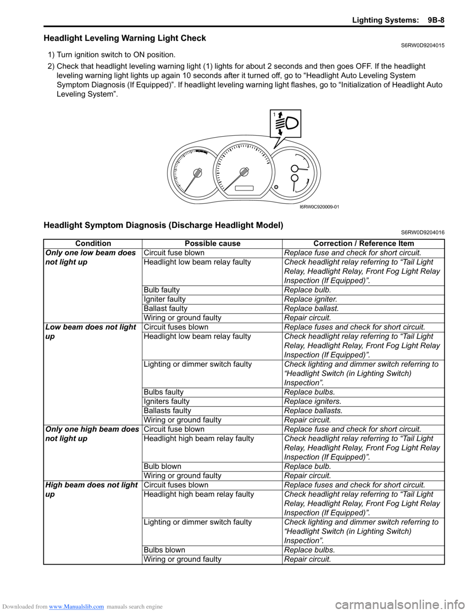
1) Turn ignition switch to ON position.
2) Check that headlight leveling warning light (1) lights for about 2 seconds and then goes OFF. If the headlight
leveling warning light lights up again 10 seconds after it turned off, go to “Headlight Auto Leveling System
Symptom Diagnosis (If Equipped)”. If headlight leveling warning light flashes, go to “Initialization of Headlight Auto
Leveling System”.
Headlight Symptom Diagnosis (Discharge Headlight Model)S6RW0D9204016
1
I6RW0C920009-01
Condition Possible cause Correction / Reference Item
Only one low beam does
not light upCircuit fuse blownReplace fuse and check for short circuit.
Headlight low beam relay faultyCheck headlight relay referring to “Tail Light
Relay, Headlight Relay, Front Fog Light Relay
Inspection (If Equipped)”.
Bulb faultyReplace bulb.
Igniter faultyReplace igniter.
Ballast faultyReplace ballast.
Wiring or ground faultyRepair circuit.
Low beam does not light
upCircuit fuses blownReplace fuses and check for short circuit.
Headlight low beam relay faultyCheck headlight relay referring to “Tail Light
Relay, Headlight Relay, Front Fog Light Relay
Inspection (If Equipped)”.
Lighting or dimmer switch faultyCheck lighting and dimmer switch referring to
“Headlight Switch (in Lighting Switch)
Inspection”.
Bulbs faultyReplace bulbs.
Igniters faultyReplace igniters.
Ballasts faultyReplace ballasts.
Wiring or ground faultyRepair circuit.
Only one high beam does
not light upCircuit fuse blownReplace fuse and check for short circuit.
Headlight high beam relay faultyCheck headlight relay referring to “Tail Light
Relay, Headlight Relay, Front Fog Light Relay
Inspection (If Equipped)”.
Bulb blownReplace bulb.
Wiring or ground faultyRepair circuit.
High beam does not light
upCircuit fuses blownReplace fuses and check for short circuit.
Headlight high beam relay faultyCheck headlight relay referring to “Tail Light
Relay, Headlight Relay, Front Fog Light Relay
Inspection (If Equipped)”.
Lighting or dimmer switch faultyCheck lighting and dimmer switch referring to
“Headlight Switch (in Lighting Switch)
Inspection”.
Bulbs blownReplace bulbs.
Wiring or ground faultyRepair circuit.
Page 1333 of 1556
Downloaded from www.Manualslib.com manuals search engine Lighting Systems: 9B-14
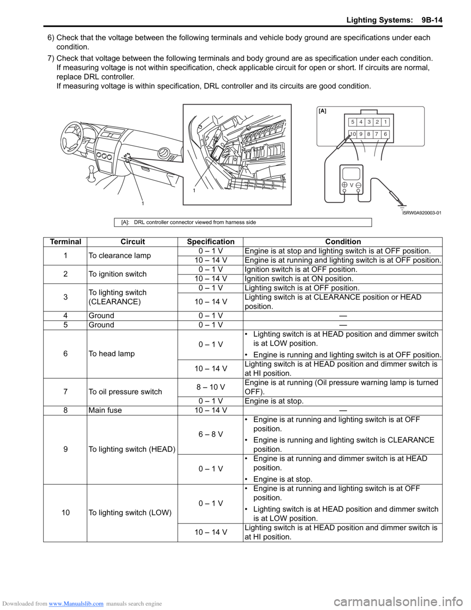
6) Check that the voltage between the following terminals and vehicle body ground are specifications under each
condition.
7) Check that voltage between the following terminals and body ground are as specification under each condition.
If measuring voltage is not within specification, check applicable circuit for open or short. If circuits are normal,
replace DRL controller.
If measuring voltage is within specification, DRL controller and its circuits are good condition.
54321
10987 6
V
1
1[A]
I5RW0A920003-01
[A]: DRL controller connector viewed from harness side
Terminal Circuit Specification Condition
1 To clearance lamp0 – 1 V Engine is at stop and lighting switch is at OFF position.
10 – 14 V Engine is at running and lighting switch is at OFF position.
2 To ignition switch0 – 1 V Ignition switch is at OFF position.
10 – 14 V Ignition switch is at ON position.
3To lighting switch
(CLEARANCE)0 – 1 V Lighting switch is at OFF position.
10 – 14 VLighting switch is at CLEARANCE position or HEAD
position.
4 Ground 0 – 1 V —
5 Ground 0 – 1 V —
6 To head lamp0 – 1 V• Lighting switch is at HEAD position and dimmer switch
is at LOW position.
• Engine is running and lighting switch is at OFF position.
10 – 14 VLighting switch is at HEAD position and dimmer switch is
at HI position.
7 To oil pressure switch8 – 10 VEngine is at running (Oil pressure warning lamp is turned
OFF).
0 – 1 V Engine is at stop.
8 Main fuse 10 – 14 V —
9 To lighting switch (HEAD)6 – 8 V• Engine is at running and lighting switch is at OFF
position.
• Engine is running and lighting switch is CLEARANCE
position.
0 – 1 V• Engine is at running and dimmer switch is at HEAD
position.
• Engine is at stop.
10 To lighting switch (LOW)0 – 1 V• Engine is at running and lighting switch is at OFF
position.
• Lighting switch is at HEAD position and dimmer switch
is at LOW position.
10 – 14 VLighting switch is at HEAD position and dimmer switch is
at HI position.
Page 1334 of 1556
Downloaded from www.Manualslib.com manuals search engine 9B-15 Lighting Systems:
Auto-On Headlight Operation Inspection (If
Equipped)
S6RW0D9204021
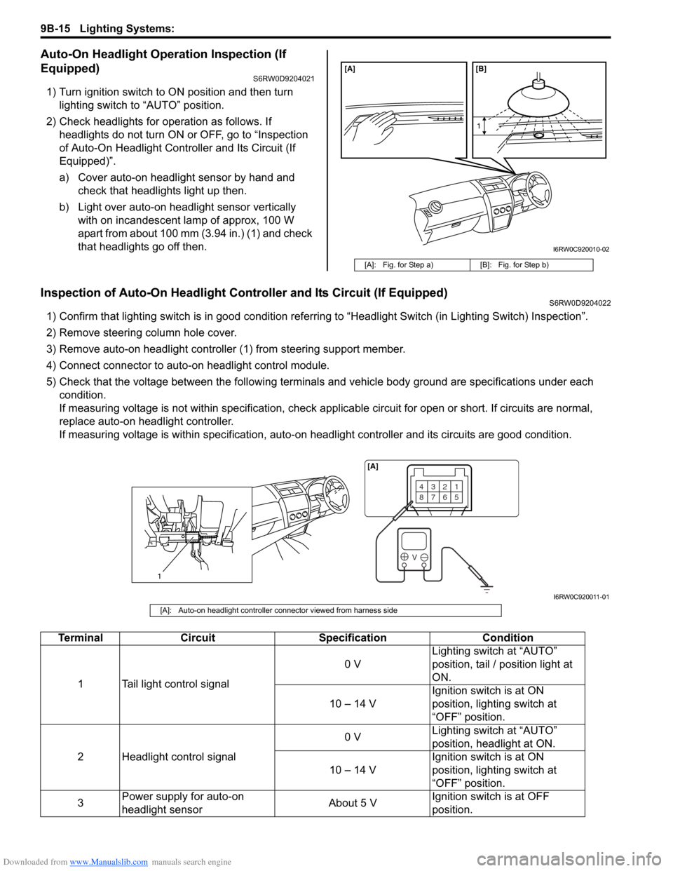
1) Turn ignition switch to ON position and then turn
lighting switch to “AUTO” position.
2) Check headlights for operation as follows. If
headlights do not turn ON or OFF, go to “Inspection
of Auto-On Headlight Controller and Its Circuit (If
Equipped)”.
a) Cover auto-on headlight sensor by hand and
check that headlights light up then.
b) Light over auto-on headlight sensor vertically
with on incandescent lamp of approx, 100 W
apart from about 100 mm (3.94 in.) (1) and check
that headlights go off then.
Inspection of Auto-On Headlight Controller and Its Circuit (If Equipped)S6RW0D9204022
1) Confirm that lighting switch is in good condition referring to “Headlight Switch (in Lighting Switch) Inspection”.
2) Remove steering column hole cover.
3) Remove auto-on headlight controller (1) from steering support member.
4) Connect connector to auto-on headlight control module.
5) Check that the voltage between the following terminals and vehicle body ground are specifications under each
condition.
If measuring voltage is not within specification, check applicable circuit for open or short. If circuits are normal,
replace auto-on headlight controller.
If measuring voltage is within specification, auto-on headlight controller and its circuits are good condition.
[A]: Fig. for Step a) [B]: Fig. for Step b)
[A] [B]
1
I6RW0C920010-02
1
4321
8765
V
[A]
I6RW0C920011-01
[A]: Auto-on headlight controller connector viewed from harness side
Terminal Circuit Specification Condition
1 Tail light control signal0 VLighting switch at “AUTO”
position, tail / position light at
ON.
10 – 14 VIgnition switch is at ON
position, lighting switch at
“OFF” position.
2 Headlight control signal0 VLighting switch at “AUTO”
position, headlight at ON.
10 – 14 VIgnition switch is at ON
position, lighting switch at
“OFF” position.
3Power supply for auto-on
headlight sensorAbout 5 VIgnition switch is at OFF
position.
Page 1335 of 1556
Downloaded from www.Manualslib.com manuals search engine Lighting Systems: 9B-16
Inspection of Headlight Leveling Control Module and Its Circuit (Headlight Auto Leveling System)S6RW0D9204023
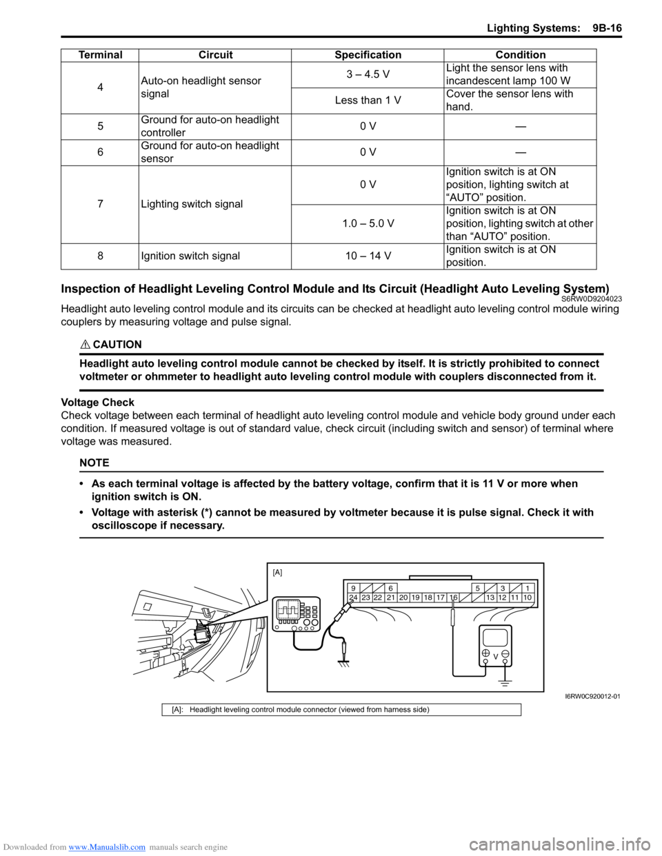
Headlight auto leveling control module and its circuits can be checked at headlight auto leveling control module wiring
couplers by measuring voltage and pulse signal.
CAUTION!
Headlight auto leveling control module cannot be checked by itself. It is strictly prohibited to connect
voltmeter or ohmmeter to headlight auto leveling control module with couplers disconnected from it.
Voltage Check
Check voltage between each terminal of headlight auto leveling control module and vehicle body ground under each
condition. If measured voltage is out of standard value, check circuit (including switch and sensor) of terminal where
voltage was measured.
NOTE
• As each terminal voltage is affected by the battery voltage, confirm that it is 11 V or more when
ignition switch is ON.
• Voltage with asterisk (*) cannot be measured by voltmeter because it is pulse signal. Check it with
oscilloscope if necessary.
4Auto-on headlight sensor
signal3 – 4.5 VLight the sensor lens with
incandescent lamp 100 W
Less than 1 VCover the sensor lens with
hand.
5Ground for auto-on headlight
controller0 V —
6Ground for auto-on headlight
sensor0 V —
7 Lighting switch signal0 VIgnition switch is at ON
position, lighting switch at
“AUTO” position.
1.0 – 5.0 VIgnition switch is at ON
position, lighting switch at other
than “AUTO” position.
8 Ignition switch signal 10 – 14 VIgnition switch is at ON
position. Terminal Circuit Specification Condition
V
10 11 12 13 16 17 18 19 2031 5 6 9
21 22 23 24
[A]
I6RW0C920012-01
[A]: Headlight leveling control module connector (viewed from harness side)