2006 SUZUKI SX4 200
[x] Cancel search: 200Page 1315 of 1556
Downloaded from www.Manualslib.com manuals search engine Wiring Systems: 9A-148
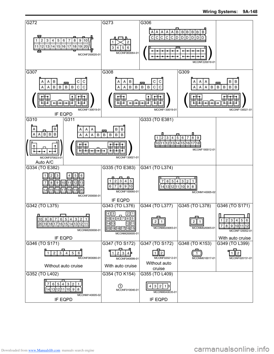
G272 G273 G306
G307 G308 G309
IF EQPD
G310 G311 G333 (TO E381)
Auto A/C
G334 (TO E382) G335 (TO E383) G341 (TO L374)
IF EQPD
G342 (TO L375) G343 (TO L376) G344 (TO L377) G345 (TO L378) G346 (TO S171)
IF EQPDWith auto cruise
G346 (TO S171) G347 (TO S172) G347 (TO S172) G348 (TO K153) G349 (TO L399)
Without auto cruise With auto cruiseWithout auto
cruise
G352 (TO L402) G354 (TO K154) G355 (TO L409)
IF EQPD IF EQPD
10
11 12 13 14 15 16 17 18 19123456789
20
MCONF200020-01
6 5 4 32 1
MCONF060064-01
AA A A A
BBBB
BB
CCC C CD DD D DD
()
MCONF220018-01
AAB CC
AAB CB B BC
( )
MCONF130019-01
AAB CC
AAB CB B BC
( )
MCONF130019-01
AAA BB
AAA BB B BB
( )
MCONF130021-01
AB
AABBB
MCONF070023-01
AAA BB
AAA BB B BB
( )
MCONF130021-01
123456789
101112131415161718
MCONF180012-01
3
256
1012
9
81341
14151617181920
11 7
MCONF200008-01
5 4 3 21
10 9 8 76
MCONF100060-01
7
654 3
21
14 13 12 11 10 9 8
MCONM140005-02
54 32 167910
20 19 18 17 16 15 14 13 12 118
MCONM200008-01
34
7
2
68910
121314
1716
1
5
11
15181920
MCONM200005-01
21
MCONM020065-01
21
MCONM020065-01
123456
789101112
MCONF120052-01
654321
MCONF060080-01
4 3 2 1
MCONF040099-01
12
MCONF020212-011
MCONM010017-01
2 1
MCONF020151-01
7
654 3
21
14 13 12 11 10 9 8
MCONM140005-02
1MCONF010046-011 2 43
MCONM040035-01
Page 1316 of 1556
Downloaded from www.Manualslib.com manuals search engine 9A-149 Wiring Systems:
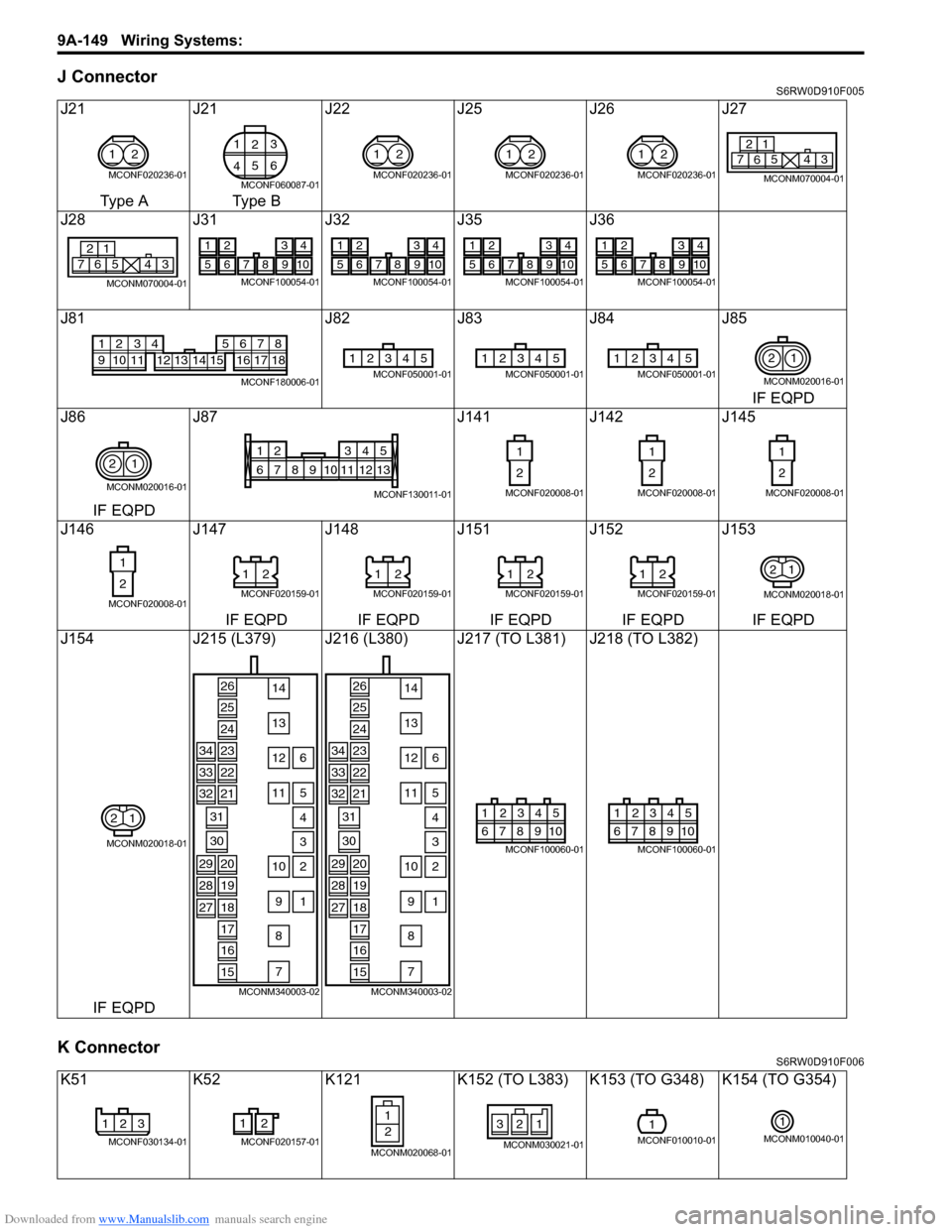
J ConnectorS6RW0D910F005
K ConnectorS6RW0D910F006
J21 J21 J22 J25 J26 J27
Type A Type B
J28 J31 J32 J35 J36
J81 J82 J83 J84 J85
IF EQPD
J86 J87 J141 J142 J145
IF EQPD
J146 J147 J148 J151 J152 J153
IF EQPD IF EQPD IF EQPD IF EQPD IF EQPD
J154 J215 (L379) J216 (L380) J217 (TO L381) J218 (TO L382)
IF EQPD
K51 K52 K121 K152 (TO L383) K153 (TO G348) K154 (TO G354)
1
2
MCONF020236-01
1
23
456
MCONF060087-01
1
2
MCONF020236-01
1
2
MCONF020236-01
1
2
MCONF020236-016 21
7543
MCONM070004-01
6 21
7543
MCONM070004-01
1234
5678910
MCONF100054-01
1234
5678910
MCONF100054-01
1234
5678910
MCONF100054-01
1234
5678910
MCONF100054-01
12
91011
34
12 13 14 15
5678
16 17 18
MCONF180006-01
12345MCONF050001-0112345MCONF050001-0112345MCONF050001-012
1
MCONM020016-01
2
1
MCONM020016-01
135
68910111324
712
MCONF130011-01
1
2
MCONF020008-01
1
2
MCONF020008-01
1
2
MCONF020008-01
1
2
MCONF020008-01
2 1
MCONF020159-01
2 1
MCONF020159-01
2 1
MCONF020159-01
2 1
MCONF020159-01
1 2
MCONM020018-01
1 2
MCONM020018-01
26
25
24
2334
2233
21
31
14
13
126
115
10
7
8
2
91
4
330
32
2029
1928
18
17
16
15
27
MCONM340003-02
26
25
24
2334
2233
21
31
14
13
126
115
10
7
8
2
91
4
330
32
2029
1928
18
17
16
15
27
MCONM340003-02
5 4 3 21
10 9 8 76
MCONF100060-01
5 4 3 21
10 9 8 76
MCONF100060-01
123
MCONF030134-01
2 1
MCONF020157-012 1
MCONM020068-01
321
MCONM030021-01
1MCONF010010-01
1
MCONM010040-01
Page 1317 of 1556
Downloaded from www.Manualslib.com manuals search engine Wiring Systems: 9A-150
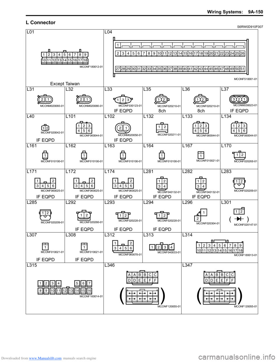
L ConnectorS6RW0D910F007
L01 L04
Except Taiwan
L31 L32 L33 L35 L36 L37
IF EQPD 8ch 8ch IF EQPD
L40 L101 L102 L132 L133 L134
IF EQPD IF EQPD
L161 L162 L163 L164 L167 L170
L171 L172 L174 L281 L282 L283
IF EQPD IF EQPD IF EQPD IF EQPD IF EQPD
L285 L292 L293 L294 L296 L301
IF EQPD IF EQPD IF EQPD
L307 L308 L312 L313 L314
IF EQPD IF EQPD
L315 L346 L347
123456789
101112131415161718
MCONF180012-01
234567891011171819202122232425261213141516
1
27282930313233343536424344454647484950513738394041
MCONF510001-01
21
MCONM020066-01
21
MCONM020066-01
123
MCONF030123-01
12
MCONF020210-01
12
MCONF020210-01
3
21
MCONM030023-01
12MCONF020042-01
1
23
456
MCONF060044-01
2
1
MCONM020058-01
12
MCONF020211-01
1
23
456
MCONF060044-01
1
23
456
MCONF060044-01
1
MCONF010100-01
1
MCONF010100-01
1
MCONF010100-01
1
MCONF010100-01
1MCONF010021-01
12
MCONF020268-01
12
3456
MCONF060025-01
12
3456
MCONF060025-01
12
3456
MCONF060025-014 3
2 1
MCONF040132-01
4 3
2 1
MCONF040132-01
12
MCONF020209-01
12
MCONF020209-01
12
MCONF020266-01
2 1
MCONF020228-01
2 1
MCONF020228-012
1
MCONF020304-01
1
2
()MCONF020147-01
1MCONF010021-011MCONF010021-01
12
3456
MCONF060078-01
2341
MCONF040033-01
123456789
15 16 17 18 11 10 12 13 14
MCONF180013-01
4 356
1214
11
1015
721
1316
9 8
MCONF160014-01
AABBCC
DDEEFF
( )
MCONF120055-01
AABBCC
DDEEFF
( )
MCONF120055-01
Page 1318 of 1556
Downloaded from www.Manualslib.com manuals search engine 9A-151 Wiring Systems:
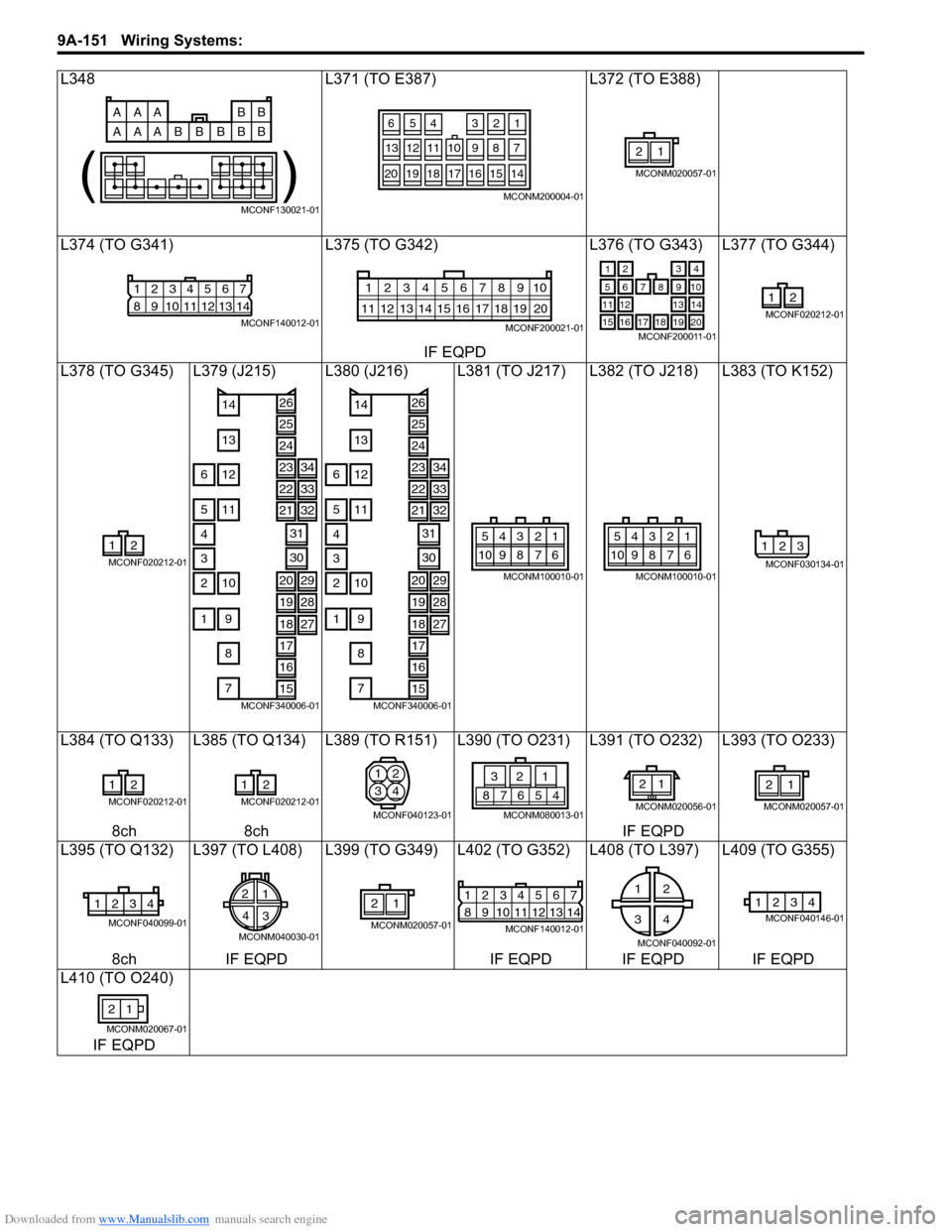
L348 L371 (TO E387) L372 (TO E388)
L374 (TO G341) L375 (TO G342) L376 (TO G343) L377 (TO G344)
IF EQPD
L378 (TO G345) L379 (J215) L380 (J216) L381 (TO J217) L382 (TO J218) L383 (TO K152)
L384 (TO Q133) L385 (TO Q134) L389 (TO R151) L390 (TO O231) L391 (TO O232) L393 (TO O233)
8ch 8ch IF EQPD
L395 (TO Q132) L397 (TO L408) L399 (TO G349) L402 (TO G352) L408 (TO L397) L409 (TO G355)
8ch IF EQPD IF EQPD IF EQPD IF EQPD
L410 (TO O240)
IF EQPD
AAA BB
AAA BB B BB
( )
MCONF130021-01
4
521
108
11
127
36
20191817161514
9 13
MCONM200004-01
21
MCONM020057-01
12567
8
9 1011121314
34
MCONF140012-01
10
11 12 13 14 15 16 17 18 19123456789
20
MCONF200021-01
21
8
3
9765
131211
1819
4
10
14
20171615MCONF200011-01
12
MCONF020212-01
12
MCONF020212-01
26
25
24
2334
2233
21
31
14
13
126
115
10
7
8
2
91
4
330
32
2029
1928
18
17
16
15
27
MCONF340006-01
26
25
24
2334
2233
21
31
14
13
126
115
10
7
8
2
91
4
330
32
2029
1928
18
17
16
15
27
MCONF340006-01
543 21
10 9 8 7 6
MCONM100010-01
543 21
10 9 8 7 6
MCONM100010-01
123
MCONF030134-01
12
MCONF020212-01
12
MCONF020212-01
1
32
4
MCONF040123-01
4 5 6 7 8
21 3
MCONM080013-01
1 2
MCONM020056-01
21
MCONM020057-01
4 3 2 1
MCONF040099-01
2
1
4
3
MCONM040030-01
21
MCONM020057-01
12567
8
9 1011121314
34
MCONF140012-01
12
34
MCONF040092-01
4 3 12MCONF040146-01
21
MCONM020067-01
Page 1319 of 1556
Downloaded from www.Manualslib.com manuals search engine Wiring Systems: 9A-152
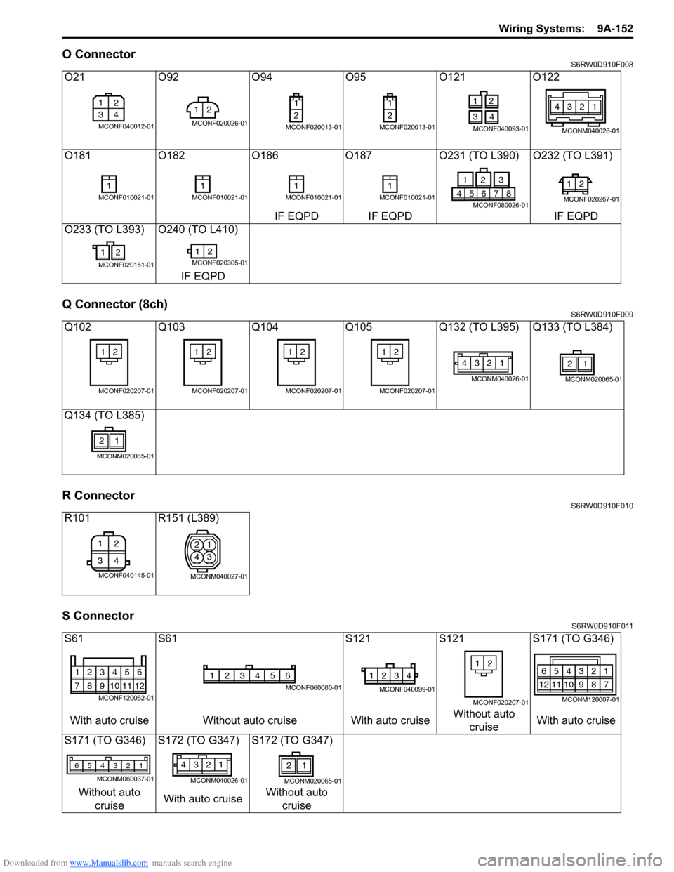
O ConnectorS6RW0D910F008
Q Connector (8ch)S6RW0D910F009
R ConnectorS6RW0D910F010
S ConnectorS6RW0D910F011
O21 O92 O94 O95 O121 O122
O181 O182 O186 O187 O231 (TO L390) O232 (TO L391)
IF EQPD IF EQPD IF EQPD
O233 (TO L393) O240 (TO L410)
IF EQPD
Q102 Q103 Q104 Q105 Q132 (TO L395) Q133 (TO L384)
Q134 (TO L385)
R101 R151 (L389)
S61 S61 S121 S121 S171 (TO G346)
With auto cruise Without auto cruise With auto cruiseWithout auto
cruiseWith auto cruise
S171 (TO G346) S172 (TO G347) S172 (TO G347)
Without auto
cruiseWith auto cruiseWithout auto
cruise
12
34
MCONF040012-01
2 1
MCONF020026-01
1
2
MCONF020013-01
1
2
MCONF020013-01
2
1
4 3
MCONF040093-01
1 2 43
MCONM040028-01
1MCONF010021-011MCONF010021-011MCONF010021-011MCONF010021-018 7 6 5 4
23 1
MCONF080026-01
2 1
MCONF020267-01
2 1
MCONF020151-01
12MCONF020305-01
2 1
MCONF020207-01
2 1
MCONF020207-01
2 1
MCONF020207-01
2 1
MCONF020207-01
1 2 43
MCONM040026-01
21
MCONM020065-01
21
MCONM020065-01
2 1
34
MCONF040145-01
2
41
3
MCONM040027-01
123456
789101112
MCONF120052-01
654321
MCONF060080-01
4 3 2 1
MCONF040099-01
2 1
MCONF020207-01
654321
121110987
MCONM120007-01
123456
MCONM060037-01
1 2 43
MCONM040026-01
21
MCONM020065-01
Page 1320 of 1556
Downloaded from www.Manualslib.com manuals search engine 9B-1 Lighting Systems:
Body, Cab and Accessories
Lighting Systems
Precautions
Precautions for Discharge Headlight Service (If Equipped)S6RW0D9200001
WARNING!
• Do not touch igniter or ballast when lighting switch is at “HEAD” position to avoid possible electric
shock.
• Do not measure voltage or resistance with tester connected to output connector of ballast or igniter
to avoid possible electric shock.
• Do not perform work where exposed to water including rain or with wet hands to avoid possible
electric shock.
• Disassembling igniter or ballast is strictly prohibited as it may cause an electric shock.
• Before inspecting or repairing discharge headlight or its peripheral parts, make sure that lighting
switch is at OFF position and battery is disconnected at negative terminal to avoid possible
electrical shock.
• Do not set lighting switch to “HEAD” position with connector disconnected or any part removed to
avoid possible electric shock.
• Do not touch glass surface of headlight bulb. Oil or grease attached on it may not only make bulb
service life shorter but also cause bulb to burst when lighting switch is turned on.
• Mercury, metal iodide and xenon gas are sealed in discharge headlight bulb. Be sure to dispose of
used discharge headlight bulb properly according to applicable rules or regulations.
Precautions in Diagnosing Troubles (Headlight Auto Leveling System)S6RW0D9200002
• Be sure to read “Air Bag Warning in Section 00” before inspection and observe what is written there.
• Replacement of height sensor and headlight leveling control module. When height sensor and/or headlight leveling
control module is replaced with new one, perform initialization of headlight auto leveling system according to
“Initialization of Headlight Auto Leveling System”.
General Description
Discharge Headlight Description (If Equipped)S6RW0D9201001
Discharge headlight provides more brightness and consumes less electricity as compared with the conventional
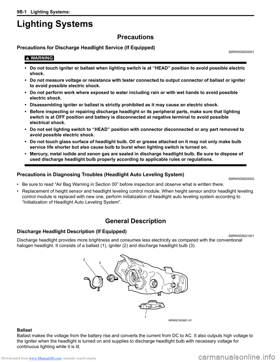
halogen headlight. It consists of a ballast (1), igniter (2) and discharge headlight bulb (3).
Ballast
Ballast makes the voltage from the battery rise and converts the current from DC to AC. It also outputs high voltage to
the igniter when the headlight is turned on and supplies to discharge headlight bulb with necessary voltage for
continuous lighting while it is lit.
2
1 3
I6RW0C920001-01
Page 1321 of 1556
Downloaded from www.Manualslib.com manuals search engine Lighting Systems: 9B-2
Igniter
Igniter generates high voltage needed to turn on the discharge headlight. It is charged with high voltage raised by the
ballast and it applies voltage pulse as high as about 20,000V to the tungsten electrode in the discharge headlight bulb.
After the discharge headlights light up, the ballast supplies voltage to bulbs.
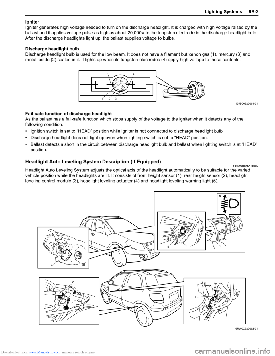
Discharge headlight bulb
Discharge headlight bulb is used for the low beam. It does not have a filament but xenon gas (1), mercury (3) and
metal iodide (2) sealed in it. It lights up when its tungsten electrodes (4) apply high voltage to these contents.
Fail-safe function of discharge headlight
As the ballast has a fail-safe function which stops supply of the voltage to the igniter when it detects any of the
following condition.
• Ignition switch is set to “HEAD” position while igniter is not connected to discharge headlight bulb
• Discharge headlight does not light up even when lighting switch is set to “HEAD” position.
• Ballast detects a short in the circuit between discharge headlight bulb and ballast when lighting switch is at “HEAD”
position.
Headlight Auto Leveling System Description (If Equipped)S6RW0D9201002
Headlight Auto Leveling System adjusts the optical axis of the headlight automatically to be suitable for the varied
vehicle position while the headlights are lit. It consists of front height sensor (1), rear height sensor (2), headlight
leveling control module (3), headlight leveling actuator (4) and headlight leveling warning light (5).
123
44
I5JB0A920001-01
4
3
5
1
2
I6RW0C920002-01
Page 1322 of 1556
Downloaded from www.Manualslib.com manuals search engine 9B-3 Lighting Systems:
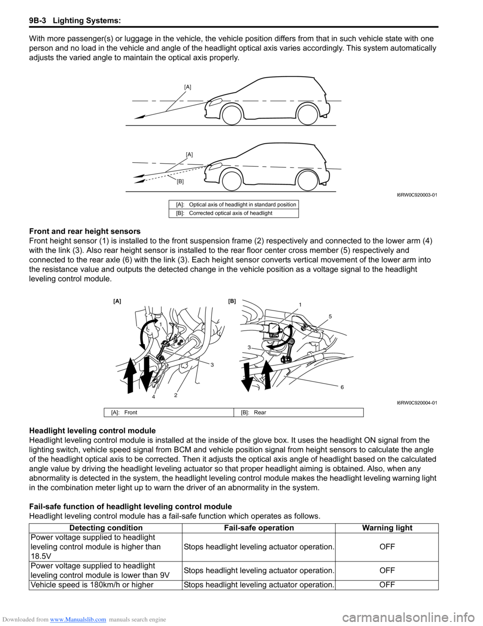
With more passenger(s) or luggage in the vehicle, the vehicle position differs from that in such vehicle state with one
person and no load in the vehicle and angle of the headlight optical axis varies accordingly. This system automatically
adjusts the varied angle to maintain the optical axis properly.
Front and rear height sensors
Front height sensor (1) is installed to the front suspension frame (2) respectively and connected to the lower arm (4)
with the link (3). Also rear height sensor is installed to the rear floor center cross member (5) respectively and
connected to the rear axle (6) with the link (3). Each height sensor converts vertical movement of the lower arm into
the resistance value and outputs the detected change in the vehicle position as a voltage signal to the headlight
leveling control module.
Headlight leveling control module
Headlight leveling control module is installed at the inside of the glove box. It uses the headlight ON signal from the
lighting switch, vehicle speed signal from BCM and vehicle position signal from height sensors to calculate the angle
of the headlight optical axis to be corrected. Then it adjusts the optical axis angle of headlight based on the calculated
angle value by driving the headlight leveling actuator so that proper headlight aiming is obtained. Also, when any
abnormality is detected in the system, the headlight leveling control module makes the headlight leveling warning light
in the combination meter light up to warn the driver of an abnormality in the system.
Fail-safe function of headlight leveling control module
Headlight leveling control module has a fail-safe function which operates as follows.
[A]
[A]
[B]
I6RW0C920003-01
[A]: Optical axis of headlight in standard position
[B]: Corrected optical axis of headlight
1
5
[A] [B]
6
3
1
2
3
4I6RW0C920004-01
[A]: Front [B]: Rear
Detecting condition Fail-safe operation Warning light
Power voltage supplied to headlight
leveling control module is higher than
18.5VStops headlight leveling actuator operation. OFF
Power voltage supplied to headlight
leveling control module is lower than 9VStops headlight leveling actuator operation. OFF
Vehicle speed is 180km/h or higher Stops headlight leveling actuator operation. OFF