Page 1134 of 1556

Downloaded from www.Manualslib.com manuals search engine 8B-95 Air Bag System:
Installation
1) Check that none of the following faulty conditions
exists.
• Bend, scratch, deformity in vehicle body where
SDM is mounted.
• Foreign matter or rust on mating surface of vehicle
body where SDM is mounted.
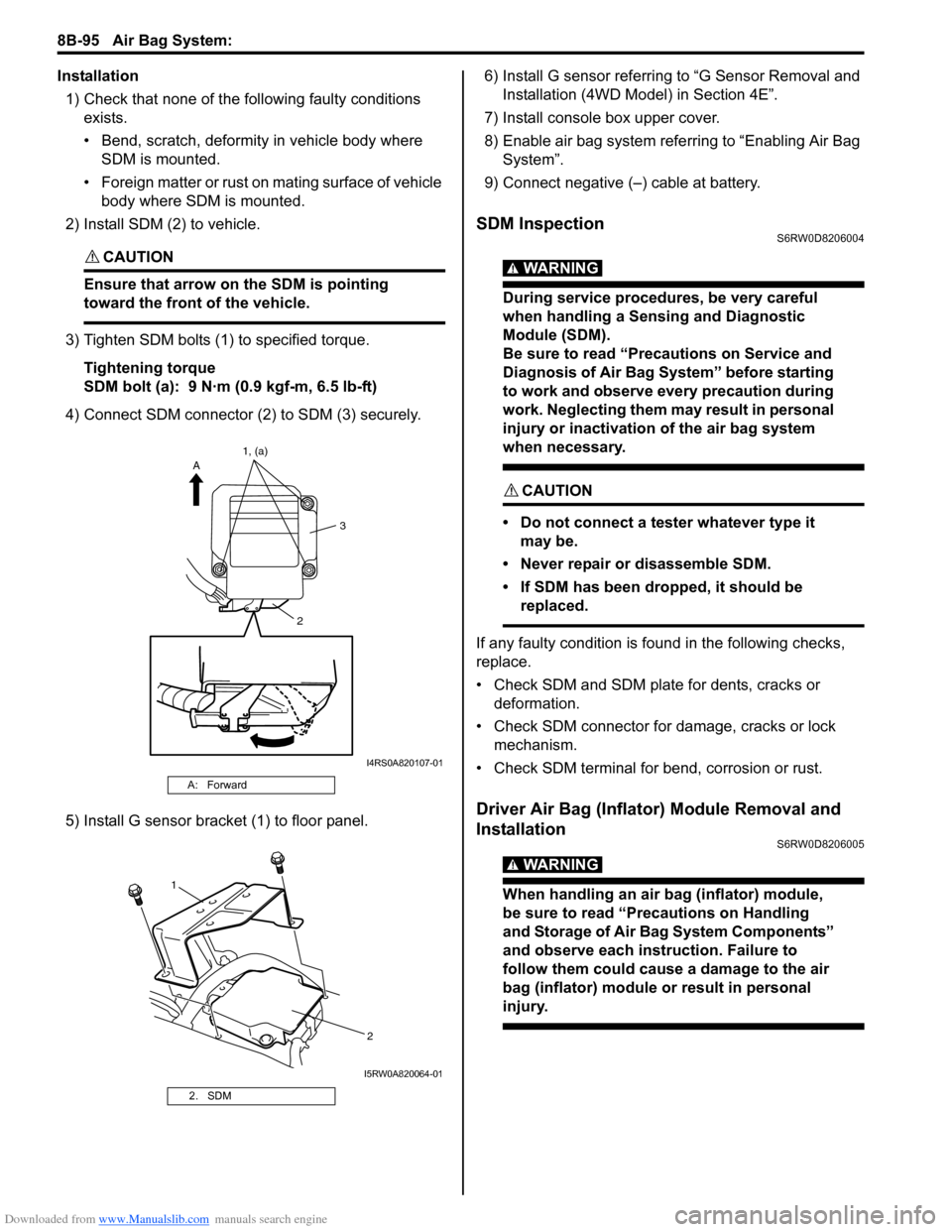
2) Install SDM (2) to vehicle.
CAUTION!
Ensure that arrow on the SDM is pointing
toward the front of the vehicle.
3) Tighten SDM bolts (1) to specified torque.
Tightening torque
SDM bolt (a): 9 N·m (0.9 kgf-m, 6.5 lb-ft)
4) Connect SDM connector (2) to SDM (3) securely.
5) Install G sensor bracket (1) to floor panel.6) Install G sensor referring to “G Sensor Removal and
Installation (4WD Model) in Section 4E”.
7) Install console box upper cover.
8) Enable air bag system referring to “Enabling Air Bag
System”.
9) Connect negative (–) cable at battery.
SDM InspectionS6RW0D8206004
WARNING!
During service procedures, be very careful
when handling a Sensing and Diagnostic
Module (SDM).
Be sure to read “Precautions on Service and
Diagnosis of Air Bag System” before starting
to work and observe every precaution during
work. Neglecting them may result in personal
injury or inactivation of the air bag system
when necessary.
CAUTION!
• Do not connect a tester whatever type it
may be.
• Never repair or disassemble SDM.
• If SDM has been dropped, it should be
replaced.
If any faulty condition is found in the following checks,
replace.
• Check SDM and SDM plate for dents, cracks or
deformation.
• Check SDM connector for damage, cracks or lock
mechanism.
• Check SDM terminal for bend, corrosion or rust.
Driver Air Bag (Inflator) Module Removal and
Installation
S6RW0D8206005
WARNING!
When handling an air bag (inflator) module,
be sure to read “Precautions on Handling
and Storage of Air Bag System Components”
and observe each instruction. Failure to
follow them could cause a damage to the air
bag (inflator) module or result in personal
injury.
A: Forward
2. SDM
23 A1, (a)
I4RS0A820107-01
1
2
I5RW0A820064-01
Page 1143 of 1556

Downloaded from www.Manualslib.com manuals search engine Air Bag System: 8B-104
Removal
1) Disconnect negative (–) cable at battery.
2) Disable air bag system referring to “Disabling Air
Bag System”.
3) Remove front bumper referring to “Front Bumper
and Rear Bumper Components in Section 9K”.
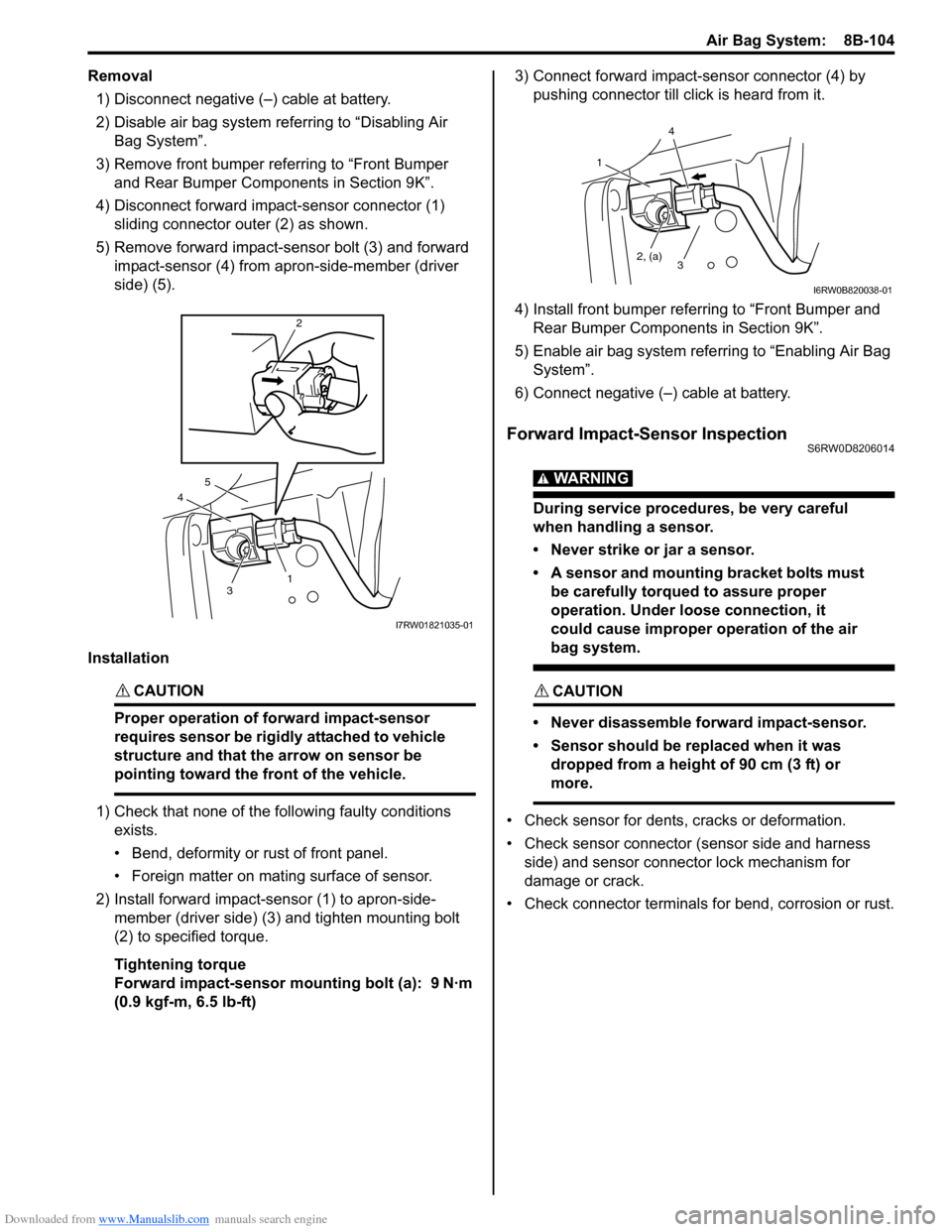
4) Disconnect forward impact-sensor connector (1)
sliding connector outer (2) as shown.
5) Remove forward impact-sensor bolt (3) and forward
impact-sensor (4) from apron-side-member (driver
side) (5).
Installation
CAUTION!
Proper operation of forward impact-sensor
requires sensor be rigidly attached to vehicle
structure and that the arrow on sensor be
pointing toward the front of the vehicle.
1) Check that none of the following faulty conditions
exists.
• Bend, deformity or rust of front panel.
• Foreign matter on mating surface of sensor.
2) Install forward impact-sensor (1) to apron-side-
member (driver side) (3) and tighten mounting bolt
(2) to specified torque.
Tightening torque
Forward impact-sensor mounting bolt (a): 9 N·m
(0.9 kgf-m, 6.5 lb-ft)3) Connect forward impact-sensor connector (4) by
pushing connector till click is heard from it.
4) Install front bumper referring to “Front Bumper and
Rear Bumper Components in Section 9K”.
5) Enable air bag system referring to “Enabling Air Bag
System”.
6) Connect negative (–) cable at battery.
Forward Impact-Sensor InspectionS6RW0D8206014
WARNING!
During service procedures, be very careful
when handling a sensor.
• Never strike or jar a sensor.
• A sensor and mounting bracket bolts must
be carefully torqued to assure proper
operation. Under loose connection, it
could cause improper operation of the air
bag system.
CAUTION!
• Never disassemble forward impact-sensor.
• Sensor should be replaced when it was
dropped from a height of 90 cm (3 ft) or
more.
• Check sensor for dents, cracks or deformation.
• Check sensor connector (sensor side and harness
side) and sensor connector lock mechanism for
damage or crack.
• Check connector terminals for bend, corrosion or rust.
4
2
3
5
1
I7RW01821035-01
1
2, (a)
4
3
I6RW0B820038-01
Page 1553 of 1556

Downloaded from www.Manualslib.com manuals search engine Keyless Start System: 10E-31
If remote controller or keyless start control module is
replaced or additional remote controller is necessary,
register ID code(s) of remote controller.
1) Sit in driver seat and close all doors.
2) Check that door lock of driver seat is unlocked.
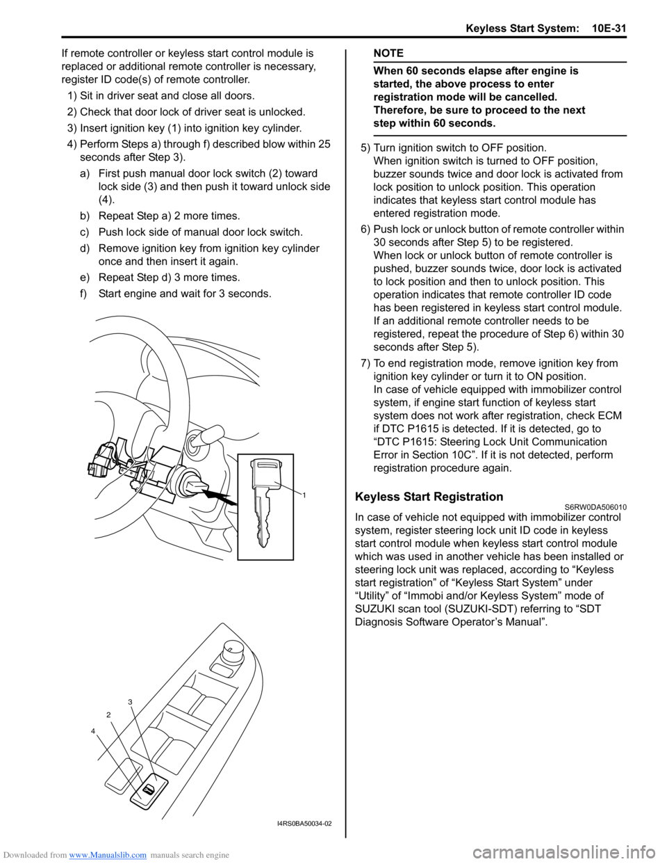
3) Insert ignition key (1) into ignition key cylinder.
4) Perform Steps a) through f) described blow within 25
seconds after Step 3).
a) First push manual door lock switch (2) toward
lock side (3) and then push it toward unlock side
(4).
b) Repeat Step a) 2 more times.
c) Push lock side of manual door lock switch.
d) Remove ignition key from ignition key cylinder
once and then insert it again.
e) Repeat Step d) 3 more times.
f) Start engine and wait for 3 seconds.NOTE
When 60 seconds elapse after engine is
started, the above process to enter
registration mode will be cancelled.
Therefore, be sure to proceed to the next
step within 60 seconds.
5) Turn ignition switch to OFF position.
When ignition switch is turned to OFF position,
buzzer sounds twice and door lock is activated from
lock position to unlock position. This operation
indicates that keyless start control module has
entered registration mode.
6) Push lock or unlock button of remote controller within
30 seconds after Step 5) to be registered.
When lock or unlock button of remote controller is
pushed, buzzer sounds twice, door lock is activated
to lock position and then to unlock position. This
operation indicates that remote controller ID code
has been registered in keyless start control module.
If an additional remote controller needs to be
registered, repeat the procedure of Step 6) within 30
seconds after Step 5).
7) To end registration mode, remove ignition key from
ignition key cylinder or turn it to ON position.
In case of vehicle equipped with immobilizer control
system, if engine start function of keyless start
system does not work after registration, check ECM
if DTC P1615 is detected. If it is detected, go to
“DTC P1615: Steering Lock Unit Communication
Error in Section 10C”. If it is not detected, perform
registration procedure again.
Keyless Start RegistrationS6RW0DA506010
In case of vehicle not equipped with immobilizer control
system, register steering lock unit ID code in keyless
start control module when keyless start control module
which was used in another vehicle has been installed or
steering lock unit was replaced, according to “Keyless
start registration” of “Keyless Start System” under
“Utility” of “Immobi and/or Keyless System” mode of
SUZUKI scan tool (SUZUKI-SDT) referring to “SDT
Diagnosis Software Operator’s Manual”.
1
2
43
I4RS0BA50034-02
Page:
< prev 1-8 9-16 17-24