2006 SUZUKI SX4 tow
[x] Cancel search: towPage 484 of 1556

Downloaded from www.Manualslib.com manuals search engine 3A-5 Drive Shaft / Axle: Front
2) Remove differential side (or center shaft side) boot
small band (1) using flat end rod (2) or the like.
3) Slide boot (1) toward the center of shaft and remove
snap ring (2) from outer race, and then take shaft out
of outer race (3).
4) Wipe off grease and remove circlip (1) used to fix
cage (2) by using snap ring pliers (3).5) Draw away cage (1) by using bearing puller (2), and
remove boot (3) from shaft.
6) Pull out differential side (or center shaft side) boot
and damper from shaft.
7) Undo caulking (5) of wheel side boot big band (1)
and small band (3) using flat end rod (2) or the like,
then pull out wheel side boot (4) from shaft.
2
1
I5RS0B310005-01
I2RH01310012-01
I5RS0B310006-01
I2RH01310014-01
I4RS0A310006-01
Page 490 of 1556

Downloaded from www.Manualslib.com manuals search engine 3A-11 Drive Shaft / Axle: Front
8) Install damper (1) to specified position on drive shaft,
if equipped.
Drive shaft damper installing position
“a”: 354 mm (13.9 in.) (right side)
“a”: 252 mm (9.9 in.) (left side)
9) Set new differential side (or center shaft side) small
band and new differential side (or center shaft side)
boot (1) on shaft temporarily, and then apply grease
to tripod joint (2). Use specified grease in tube
included in spare parts.
10) Install tripod joint spider (3) on shaft using special
tool with hammer, directing its chamfered spline
toward wheel side, and then fasten it with new snap
ring (4) using snap ring pliers (5).
Special tool
(A): 09925–98221
11) Apply grease (including in spare parts) to inside of
tripod joint housing (1), joint it with tripod joint.
Grease color
“A”: Dark gray
Amount
“A”: 70 – 90 g (2.5 – 3.2 oz)12) Fit boot (1) to grooves of shaft and housing (2) adjust
length to specification below.
13) Insert screw driver into boot and allow air to enter
boot so that air pressure in boot becomes the same
as atmospheric pressure.
Drive shaft boot fixing position (distance
between housing end and small boot band)
Left side drive shaft “a”: 153.9 mm (6.06 in.)
Right side drive shaft “b”: 178 mm (7.01 in.)
CAUTION!
• Bend each boot band against forward
rotation.
• Do not squeeze or distort boot when
fastening it with bands. Distorted boot
caused by squeezing air may reduce its
durability.
14) Place differential side (or center shaft side) boot new
big band (3) and new small band (4) onto boot
putting band outer end (1) against forward rotation
(2) as shown in figure.
I4RS0B310002-01
I7RW01311004-01
I4RS0B310003-01
[A]: Drive shaft inserted into differential side
[B]: Drive shaft inserted into center shaft side
I4RS0B310004-01
I4RS0B310007-01
Page 573 of 1556

Downloaded from www.Manualslib.com manuals search engine Brake Control System and Diagnosis: 4A-2
Brake Pedal Foot Protection System Construction (If Equipped)S6RW0D4101004
Should a front crash occur and the engine push the dash panel toward the interior side, the brake pedal bracket is also
pushed toward the interior side. In this case, the brake pedal lever comes off from the brake pedal, thereby preventing
the brake pedal from moving rearward.
CAUTION!
Never disassemble brake pedal assembly. Disassemble will spoil its original function. If faulty
condition is found, replace it with new one.
[A]: Before crash 2. Brake booster 5. Brake pedal bracket
[B]: After crash 3. Brake pedal lever
1. Brake pedal 4. Booster push clevis rod
I6RW0C410001-02
Page 579 of 1556

Downloaded from www.Manualslib.com manuals search engine Brake Control System and Diagnosis: 4A-8
Brake Fluid Level InspectionS6RW0D4106004
CAUTION!
Do not use shock absorber fluid or any other
fluid which contains mineral oil. Do not use a
container which has been used for mineral oil
or a container which is wet from water.
Mineral oil will cause swelling and distortion
of rubber parts in hydraulic brake system and
water mixed into brake fluid will lower fluid
boiling point. Keep all fluid containers
capped to prevent contamination.
NOTE
Be sure to use particular brake fluid either as
indicated on reservoir cap of that vehicle or
recommended in owner’s manual which
comes along with that vehicle. Use of any
other fluid is strictly prohibited.
Fluid level should be between MIN and MAX
lines marked on reservoir.
When brake warning light lights sometimes
during driving, replenish fluid to MAX level.
When fluid decreases quickly, inspect brake
system for leakage. Correct leaky points and
then refill to specified level.
1) Check master cylinder, reservoir and reservoir hose
(if equipped) for crack, damage and brake fluid
leakage. If any faulty condition exists, correct or
replace.
2) Check that brake fluid level is between MAX (1) and
MIN marks (2) on reservoir.
Brake Light Switch AdjustmentS6RW0D4106005
Adjustment should be made as follows. Pull up brake
pedal toward you and while holding it there, adjust
switch position so that clearance between end of thread
and brake pedal is as specified. Then lock it by turning
clockwise.
Clearance between brake pedal and brake light
switch
“a”: 0.5 – 1.5 mm (0.02 – 0.05 in.)
Air Bleeding of Brake SystemS6RW0D4106006
CAUTION!
Brake fluid is extremely damaging to paint. If
fluid should accidentally touch painted
surface, immediately wipe fluid from paint
and clean painted surface.
Bleeding operation is necessary to remove air whenever
it entered hydraulic brake system.
Hydraulic lines of brake system are based on the
diagonal split system. When a brake pipe or hose was
disconnected at the wheel, bleeding operation must be
performed at both ends of the line of the removed pipe or
hose. When any joint part of the master cylinder of other
joint part between the master cylinder and each brake
(wheel) was removed, the hydraulic brake system must
be bled at all 4 wheel brakes.
NOTE
Perform bleeding operation starting with rear
brake caliper or wheel cylinder farthest from
master cylinder and then at front caliper of
the same brake line. Do the same on the
other brake line.
1
2
I7RW01410004-01
1. Right front brake caliper 3. Right rear wheel cylinder
2. Left front brake caliper 4. Left rear wheel cylinder
I5RW0A410005-01
I7RW01410005-01
Page 649 of 1556

Downloaded from www.Manualslib.com manuals search engine Automatic Transmission/Transaxle: 5A-1
Transmission / Transaxle
Automatic Transmission/Transaxle
Precautions
Precautions in Diagnosing TroubleS6RW0D5100001
• Do not disconnect couplers from TCM, battery cable
from battery, TCM ground wire harness from engine or
main fuse before checking the diagnostic information
(DTC, freeze frame data, etc.) stored in TCM memory.
Such disconnection will clear memorized information
in TCM memory.
• Diagnostic information stored in TCM memory can be
cleared as well as checked by using SUZUKI scan
tool or CAN communication OBD generic scan tool.
Before using scan tool, read its Operator’s
(Instruction) Manual carefully to have good
understanding as to what functions are available and
how to use it.
It is indistinguishable which module turns on MIL
because not only ECM but also TCM turns on MIL.
Therefore, check both ECM and TCM for DTC when
MIL lights on.
When checking TCM for DTC, keep in mind that DTC
is displayed on the scan tool as follows depending on
the scan tool used.
– SUZUKI scan tool displays DTC detected by TCM.
– CAN communication OBD generic scan tool
displays DTC detected by each of ECM and TCM
simultaneously.
• Be sure to read “Precautions for Electrical Circuit
Service in Section 00” before inspection and observe
what is written there.
• TCM replacement
– When substituting a known-good TCM, check that
all relays and actuators have resistance of
specified value.
Neglecting this check may result in damage to good
TCM.
• Communication of ECM, BCM, combination meter,
keyless start control module (if equipped), ABS
control module, 4WD control module (if equipped),
TCM and DLC, is established by CAN (Controller
Area Network). (For more detail of CAN
communication for ECM, refer to “CAN
Communication System Description”). Therefore,
handle CAN communication line with care referring to
“Precaution for CAN Communication System in
Section 00”.
Precautions for Disassembly and ReassemblyS6RW0D5100002
When repairing automatic transaxle, it is necessary to
conduct the on-vehicle test to investigate where the
cause of the trouble lies first.
Then whether overhaul should be done or not is
determined. If the transaxle is disassembled without
such preliminary procedure, not only the cause of the
trouble would be unknown, but also a secondary trouble
may occur and often time would be wasted.
As the automatic transaxle consists of high precision
component, the following cautions should be strictly
observed when handling its parts in disassembly and
reassembly.
• Disassembling valve body assembly is prohibited
essentially. However, a few parts can be
disassembled. When disassembling valve body
component parts, confirm whether their parts are
allowed to disassemble or not referring to “Valve Body
Assembly Disassembly and Reassembly”.
• When component part of forward clutch, direct clutch,
2nd brake and/or O/D and 2nd coast brake, namely
clutch disc, brake disc, retaining plate and/or
separator plate, have been replaced, all learned
contents, which have been stored in TCM memory by
executing learning control, should be initialized
referring to “Learning Control Initialization”.
• Make sure to wash dirt off from the transaxle so that
no such dirt will enter the transaxle during
dismounting and remounting.
• Select a clean place free from dust and dirt for
overhauling.
• Place a rubber mat on the work bench to protect parts
from damage.
• Work gloves or shop cloth should not be used. (Use a
nylon cloth or a paper towel.)
• When separating the case joint, do not pry with a
screwdriver or such but tap with a plastic hammer
lightly.
• Make sure to wash dirt off from the transaxle so that
no such dirt will enter the transaxle during
disassembly and reassembly.
• Wash the disassembled parts in ATF (Automatic
Transaxle Fluid) or kerosene (using care not to allow
ATF or kerosene to get on your face, etc.) and confirm
that each fluid passage is not clogged by blowing air
into it. But use kerosene to wash the discs, resin
washers and rubber parts.
• Replace each gasket, oil seal and O-ring with a new
one.
• Apply ATF to sliding or rotating parts before
reassembly.
Page 816 of 1556

Downloaded from www.Manualslib.com manuals search engine 5B-4 Manual Transmission/Transaxle:
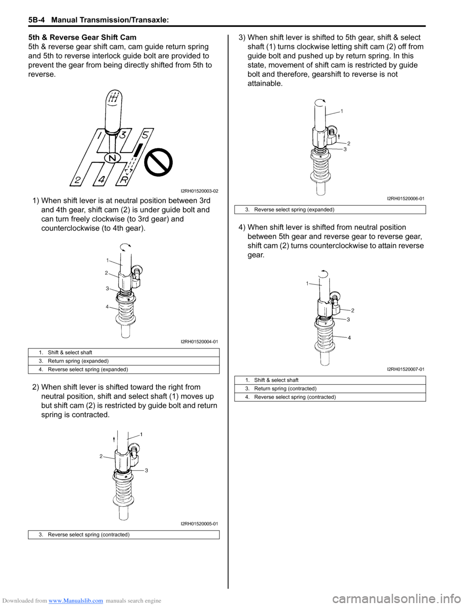
5th & Reverse Gear Shift Cam
5th & reverse gear shift cam, cam guide return spring
and 5th to reverse interlock guide bolt are provided to
prevent the gear from being directly shifted from 5th to
reverse.
1) When shift lever is at neutral position between 3rd
and 4th gear, shift cam (2) is under guide bolt and
can turn freely clockwise (to 3rd gear) and
counterclockwise (to 4th gear).
2) When shift lever is shifted toward the right from
neutral position, shift and select shaft (1) moves up
but shift cam (2) is restricted by guide bolt and return
spring is contracted.3) When shift lever is shifted to 5th gear, shift & select
shaft (1) turns clockwise letting shift cam (2) off from
guide bolt and pushed up by return spring. In this
state, movement of shift cam is restricted by guide
bolt and therefore, gearshift to reverse is not
attainable.
4) When shift lever is shifted from neutral position
between 5th gear and reverse gear to reverse gear,
shift cam (2) turns counterclockwise to attain reverse
gear.
1. Shift & select shaft
3. Return spring (expanded)
4. Reverse select spring (expanded)
3. Reverse select spring (contracted)
I2RH01520003-02
I2RH01520004-01
I2RH01520005-01
3. Reverse select spring (expanded)
1. Shift & select shaft
3. Return spring (contracted)
4. Reverse select spring (contracted)
I2RH01520006-01
I2RH01520007-01
Page 1037 of 1556

Downloaded from www.Manualslib.com manuals search engine Seat Belts: 8A-6
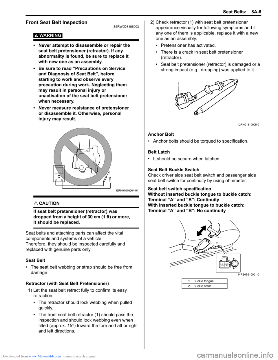
Front Seat Belt InspectionS6RW0D8106003
WARNING!
• Never attempt to disassemble or repair the
seat belt pretensioner (retractor). If any
abnormality is found, be sure to replace it
with new one as an assembly.
• Be sure to read “Precautions on Service
and Diagnosis of Seat Belt”, before
starting to work and observe every
precaution during work. Neglecting them
may result in personal injury or
unactivation of the seat belt pretensioner
when necessary.
• Never measure resistance of pretensioner
or disassemble it. Otherwise, personal
injury may result.
CAUTION!
If seat belt pretensioner (retractor) was
dropped from a height of 30 cm (1 ft) or more,
it should be replaced.
Seat belts and attaching parts can affect the vital
components and systems of a vehicle.
Therefore, they should be inspected carefully and
replaced with genuine parts only.
Seat Belt
• The seat belt webbing or strap should be free from
damage.
Retractor (with Seat Belt Pretensioner)
1) Let the seat belt retract fully to confirm its easy
retraction.
• The retractor should lock webbing when pulled
quickly.
• The front seat belt retractor (1) should pass the
inspection and should lock webbing even when
tilted (approx. 15°) toward the fore and aft or right
and left directions.2) Check retractor (1) with seat belt pretensioner
appearance visually for following symptoms and if
any one of them is applicable, replace it with a new
one as an assembly.
• Pretensioner has activated.
• There is a crack in seat belt pretensioner
(retractor).
• Seat belt pretensioner (retractor) is damaged or a
strong impact (e.g., dropping) was applied to it.
Anchor Bolt
• Anchor bolts should be torqued to specification.
Belt Latch
• It should be secure when latched.
Seat Belt Buckle Switch
Check driver side seat belt switch and passenger side
seat belt switch for continuity by using ohmmeter.
Seat belt switch specification
Without inserted buckle tongue to buckle catch:
Terminal “A” and “B”: Continuity
With inserted buckle tongue to buckle catch:
Terminal “A” and “B”: No continuityI2RH01810004-01
1. Buckle tongue
2. Buckle catch
I2RH01810005-01
I4RS0B810001-01
Page 1041 of 1556

Downloaded from www.Manualslib.com manuals search engine Air Bag System: 8B-2
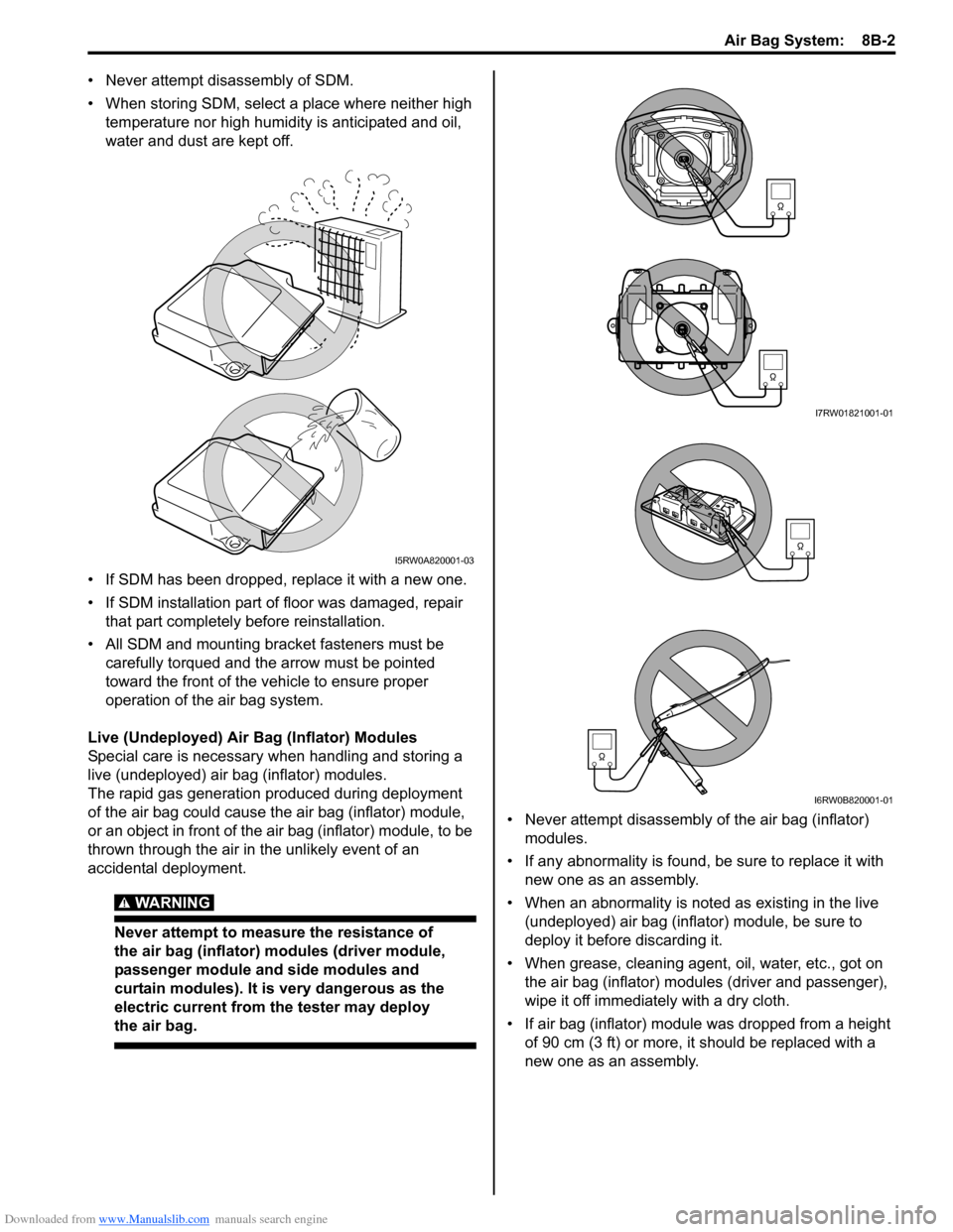
• Never attempt disassembly of SDM.
• When storing SDM, select a place where neither high
temperature nor high humidity is anticipated and oil,
water and dust are kept off.
• If SDM has been dropped, replace it with a new one.
• If SDM installation part of floor was damaged, repair
that part completely before reinstallation.
• All SDM and mounting bracket fasteners must be
carefully torqued and the arrow must be pointed
toward the front of the vehicle to ensure proper
operation of the air bag system.
Live (Undeployed) Air Bag (Inflator) Modules
Special care is necessary when handling and storing a
live (undeployed) air bag (inflator) modules.
The rapid gas generation produced during deployment
of the air bag could cause the air bag (inflator) module,
or an object in front of the air bag (inflator) module, to be
thrown through the air in the unlikely event of an
accidental deployment.
WARNING!
Never attempt to measure the resistance of
the air bag (inflator) modules (driver module,
passenger module and side modules and
curtain modules). It is very dangerous as the
electric current from the tester may deploy
the air bag.
• Never attempt disassembly of the air bag (inflator)
modules.
• If any abnormality is found, be sure to replace it with
new one as an assembly.
• When an abnormality is noted as existing in the live
(undeployed) air bag (inflator) module, be sure to
deploy it before discarding it.
• When grease, cleaning agent, oil, water, etc., got on
the air bag (inflator) modules (driver and passenger),
wipe it off immediately with a dry cloth.
• If air bag (inflator) module was dropped from a height
of 90 cm (3 ft) or more, it should be replaced with a
new one as an assembly.
I5RW0A820001-03
I7RW01821001-01
I6RW0B820001-01