2006 SUZUKI SX4 consumption
[x] Cancel search: consumptionPage 60 of 1556

Downloaded from www.Manualslib.com manuals search engine 1A-10 Engine General Information and Diagnosis:
ECM Transmission Data
ECM Reception Data
BCM TCMCombination
Meter
DATA ECM Transmit
Brake pedal switch signal
Vehicle speed signal
Engine speed signal
Engine torque signal
Accelerator pedal position signal
4WD Control
ModuleKeyless Start
Control
Module
A/C refrigerant pressure
signal
A/C compressor clutch signal
Engine type signal
Immobilizer indicator light control
signal
MIL control signal
Engine coolant temperature signal
Fuel level signal
Fuel consumption signal
Throttle position signal
Driving cycle active
Warm up cycle active
Odometer signal
I6RW0D110003-02
DATA ECM Receive
ABS control
module
Transmission oil temperature signal
Transmission warning light signal Vehicle speed pulse signal A/T selector lever position signal
Transmission actual gear position signal
Wheel speed signal (front right)
Wheel speed signal (front left)
ABS indication signal
A/C switch ON signal
Electric load signalBCM
4WD mode status
Torque request signalTCM
MIL control signal4WD control
module
I6RW0D110013-02
Page 97 of 1556

Downloaded from www.Manualslib.com manuals search engine Engine General Information and Diagnosis: 1A-47
Engine overheatingInoperative thermostat“Thermostat Inspection in Section 1F”
Poor water pump performance“Water Pump Inspection in Section 1F”
Clogged or leaky radiator“Radiator On-Vehicle Inspection and Cleaning
in Section 1F”
Improper engine oil grade“Engine Oil and Filter Change in Section 0B”
Clogged oil filter or oil strainer“Oil Pressure Check in Section 1E”
Poor oil pump performance“Oil Pressure Check in Section 1E”
Faulty radiator cooling fan control
system“Radiator Cooling Fan Control System Check”
Dragging brakesCondition “Dragging brakes” in “Brakes
Symptom Diagnosis in Section 4A”
Slipping clutch (for M/T model)Condition “Slipping clutch” in “Clutch System
Symptom Diagnosis in Section 5C” for M/T
model
Blown cylinder head gasket“Cylinder Head Inspection in Section 1D”
Air mixed in cooling system
Poor gasoline mileageLeaks or loose connection of high-
tension cord“High-Tension Cord Removal and Installation
in Section 1H”
Faulty spark plug (improper gap, heavy
deposits and burned electrodes, etc.)“Spark Plug Inspection in Section 1H”
Malfunctioning EGR valve“EGR Valve Inspection (If Equipped) in Section
1B”
High idle speedCondition “Improper engine idling or engine
fails to idle”
Poor performance of ECT sensor, MAF
sensor“Engine Coolant Temperature (ECT) Sensor
Inspection in Section 1C”, or “Intake Air
Temperature (IAT) Sensor Inspection in
Section 1C”
Faulty electric throttle body assembly“Electric Throttle Body Assembly On-Vehicle
Inspection in Section 1C”
Faulty APP sensor assembly“Accelerator Pedal Position (APP) Sensor
Assembly Inspection in Section 1C”
Faulty fuel injector(s)“Fuel Injector Circuit Check”
Faulty ECM
Low compression“Compression Check in Section 1D”
Poor valve seating“Valves and Valve Guides Inspection in
Section 1D”
Dragging brakesCondition “Dragging brakes” in “Brakes
Symptom Diagnosis in Section 4A”
Slipping clutch (for M/T model)Condition “Slipping clutch” in “Clutch System
Symptom Diagnosis in Section 5C” for M/T
model
Thermostat out of order“Thermostat Inspection in Section 1F”
Improper tire pressure“Tires Description in Section 2D”
Camshaft position control (VVT) system
out of order (for engine with VVT
system)“Oil Control Valve Inspection (For Engine with
VVT) in Section 1D”
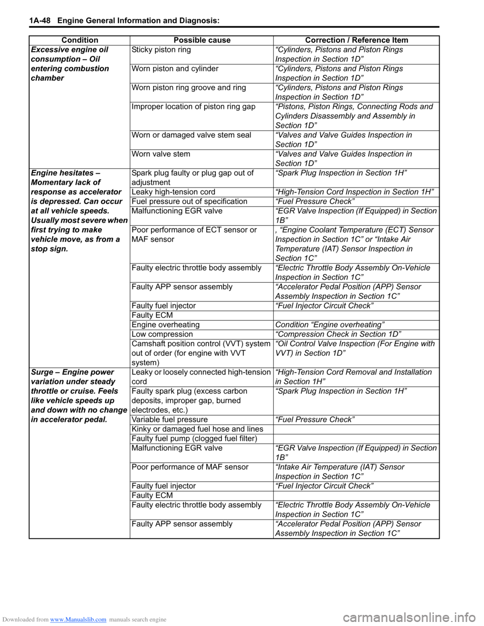
Excessive engine oil
consumption – Oil
leakageBlown cylinder head gasket“Cylinder Head Inspection in Section 1D”
Leaky camshaft oil seals“Camshaft, Tappet and Shim Inspection in
Section 1D” Condition Possible cause Correction / Reference Item
Page 98 of 1556

Downloaded from www.Manualslib.com manuals search engine 1A-48 Engine General Information and Diagnosis:
Excessive engine oil
consumption – Oil
entering combustion
chamberSticky piston ring“Cylinders, Pistons and Piston Rings
Inspection in Section 1D”
Worn piston and cylinder“Cylinders, Pistons and Piston Rings
Inspection in Section 1D”
Worn piston ring groove and ring“Cylinders, Pistons and Piston Rings
Inspection in Section 1D”
Improper location of piston ring gap“Pistons, Piston Rings, Connecting Rods and
Cylinders Disassembly and Assembly in
Section 1D”
Worn or damaged valve stem seal“Valves and Valve Guides Inspection in
Section 1D”
Worn valve stem“Valves and Valve Guides Inspection in
Section 1D”
Engine hesitates –
Momentary lack of
response as accelerator
is depressed. Can occur
at all vehicle speeds.
Usually most severe when
first trying to make
vehicle move, as from a
stop sign.Spark plug faulty or plug gap out of
adjustment“Spark Plug Inspection in Section 1H”
Leaky high-tension cord“High-Tension Cord Inspection in Section 1H”
Fuel pressure out of specification“Fuel Pressure Check”
Malfunctioning EGR valve“EGR Valve Inspection (If Equipped) in Section
1B”
Poor performance of ECT sensor or
MAF sensor, “Engine Coolant Temperature (ECT) Sensor
Inspection in Section 1C” or “Intake Air
Temperature (IAT) Sensor Inspection in
Section 1C”
Faulty electric throttle body assembly“Electric Throttle Body Assembly On-Vehicle
Inspection in Section 1C”
Faulty APP sensor assembly“Accelerator Pedal Position (APP) Sensor
Assembly Inspection in Section 1C”
Faulty fuel injector“Fuel Injector Circuit Check”
Faulty ECM
Engine overheatingCondition “Engine overheating”
Low compression“Compression Check in Section 1D”
Camshaft position control (VVT) system
out of order (for engine with VVT
system)“Oil Control Valve Inspection (For Engine with
VVT) in Section 1D”
Surge – Engine power
variation under steady
throttle or cruise. Feels
like vehicle speeds up
and down with no change
in accelerator pedal.Leaky or loosely connected high-tension
cord“High-Tension Cord Removal and Installation
in Section 1H”
Faulty spark plug (excess carbon
deposits, improper gap, burned
electrodes, etc.)“Spark Plug Inspection in Section 1H”
Variable fuel pressure“Fuel Pressure Check”
Kinky or damaged fuel hose and lines
Faulty fuel pump (clogged fuel filter)
Malfunctioning EGR valve“EGR Valve Inspection (If Equipped) in Section
1B”
Poor performance of MAF sensor“Intake Air Temperature (IAT) Sensor
Inspection in Section 1C”
Faulty fuel injector“Fuel Injector Circuit Check”
Faulty ECM
Faulty electric throttle body assembly“Electric Throttle Body Assembly On-Vehicle
Inspection in Section 1C”
Faulty APP sensor assembly“Accelerator Pedal Position (APP) Sensor
Assembly Inspection in Section 1C” Condition Possible cause Correction / Reference Item
Page 285 of 1556

Downloaded from www.Manualslib.com manuals search engine Engine Mechanical: 1D-3
Camshaft Position Control (VVT Variable Valve Timing) System DescriptionS6RW0D1401002
System Description
The VVT system is an electronic control system which continuously vary and optimize the intake valve timing in
response to the engine operating condition.
The optimized intake valve timing produce such an air intake with high efficiency that both the higher power generation
and lower fuel consumption can be attained in the whole engine speed range from low to high. In the area of the
average engine load, low emission of nitrogen oxides (NOx) and high fuel efficiency can also be attained by making
the valve opening overlap between the intake and exhaust valves longer.
For the brief of the system operation, the intake valve timing is varied by the cam timing sprocket (1) which varies the
rotational phase between the intake camshaft (3) and sprocket. The rotor (2) in the cam timing sprocket is actuated by
switching or adjusting the hydraulic pressure applied to the chambers for the timing advancing (7) and/or retarding (6).
To switch or adjust the hydraulic pressure appropriately, ECM operates the oil control valve (12) with detecting the
engine speed, intake air value, throttle opening, engine coolant temperature and camshaft position (angle).
1
4
5
10
8
9
2
7
6
12
11
3
60˚ (variable angle)
Most retarded timing Most advanced timing
Exhaust valveIntake valve
Crank angle
Overlap of valves
Valve lift
I5RW0C140002-01
4. Oil passage to chamber for timing retarding 8. Oil filter 10. Oil pan
5. Oil passage to chamber for timing advancing 9. Oil pump 11. Control signal from ECM
Page 470 of 1556

Downloaded from www.Manualslib.com manuals search engine 2D-1 Wheels and Tires:
Suspension
Wheels and Tires
General Description
Tires DescriptionS6RW0D2401001
The tire is of tubeless type. The tire is designed to
operate satisfactorily with loads up to the full rated load
capacity when inflated to the recommended inflation
pressures.
Correct tire pressures and driving habits have an
important influence on tire life. Heavy cornering,
excessively rapid acceleration, and unnecessary sharp
braking increase tire wear.
Tire Placard
The “Tire Placard” is located on the left or right door lock
pillar and should be referred to tire information.
The placard lists the maximum load, tire size and cold
tire pressure where applicable.
NOTE
Whether rim size and/or maximum load are
listed or not depends on regulations of each
country.
Inflation of Tires
The pressure recommended for any model is carefully
calculated to give a satisfactory ride, stability, steering,
tread wear, tire life and resistance to bruises.
Tire pressure, with tires cold, (after vehicle has set for 3
hours or more, or driven less than one mile) should be
checked monthly or before any extended trip. Set to the
specifications on the “Tire Placard” located on the left or
right door lock pillar.
It is normal for tire pressure to increase when the tires
become hot during driving.
Do not bleed or reduce tire pressure after driving.
Bleeding reduces the “Cold Inflation Pressure”.
Higher than recommended pressure can cause:
• Hard ride
• Tire bruising or carcass damage
• Rapid tread wear at center of tire
Unequal pressure on same axle can cause:
• Uneven braking
• Steering lead
• Reduced handling
• Swerve on accelerationLower than recommended pressure can cause:
• Tire squeal on turns
• Hard Steering
• Rapid and uneven wear on the edges of the tread
• Tire rim bruises and rupture
• Tire cord breakage
• High tire temperature
• Reduced handling
• High fuel consumption
Matched Tires and Wheels (Steel Type)
Tires and wheels are match mounted at the assembly
plant.
This means that the radially stiffest part of the tire, or
“high spot”, is matched to the smallest radius or “low
spot” of the wheel.
This is done to provide the smoothest possible ride.
The “high spot” of the tire is originally marked by paint
dot (1) on the outboard sidewall. This paint dot will
eventually wash off the tire.
The “low spot” of the wheel is originally marked by paint
dot (2) on the wheel rim-flange. Properly assembled, the
wheel rims’ paint dot should be aligned with the tires’
paint dot as shown in figure.
Whenever a tire is dismounted from its wheel, it should
be remounted so that the tire and wheel are matched. If
the tire’s paint dot cannot be located, a line should be
scribed on the tire and wheel before dismounting to
assure that it is remounted in the same position.
I2RH01240001-01
Page 997 of 1556

Downloaded from www.Manualslib.com manuals search engine Air Conditioning System: Automatic Type 7B-57
SUN LOAD (W/m2): This parameter indicates the
amount of sunlight detected by sunload sensor.
MODE CONT SWITCH (Air flow selector position,
AUTO, FACE, B/L, FOOT, D/F, DEF): This
parameter indicates the selected position of air flow
selector.
FAN CONT SWITCH (Blower speed selector, AUTO,
OFF, 1st – 8th): This parameter indicates the
selected position of blower speed selector.
FAN DESIRE VOLT (Fan desired voltage, V): This
parameter indicates the consumption voltage of
blower motor.
AIR MIX POS SENSOR (Temperature control
actuator position sensor, V): This parameter
indicates the input signal from position sensor in
temperature control actuator.
MODE POS SENSOR (Air flow control actuator
position sensor, V): This parameter indicates the
input signal from position sensor in air flow control
actuator.
A/C CONT SIG (A/C control signal, ON, OFF): This
parameter indicates the state of A/C switch.BLOWER LOAD SIG (Blower fan load signal, ON,
OFF): ON: Position of blower speed selector is 1st
position or more.
OFF: Position of blower speed selector is OFF
position.
AIR INTAKE MODE (Air intake selector position,
AUTO, FRE, REC): This parameter indicates the
selected position of air intake selector.
REFRIGERANT PRESSURE (A/C refrigerant absolute
pressure, kPa): This parameter indicates the A/C
refrigerant absolute pressure calculated by ECM
A/C COMP CLUCH (A/C compressor magnet clutch,
ON, OFF): This parameter indicates the state of the
A/C compressor magnet clutch.
VEHICLE SPEED (km/h, mph): This parameter
indicates the vehicle speed calculated by ECM.
ENGINE TYPE (Engine type signal, J20, M16 or
M15): This parameter indicates the engine type
signal transmitted by ECM.
METER SPEC (Combination meter spec signal, EU,
UK, US, Canada, DOM): This parameter indicates
the combination meter spec signal transmitted by
combination meter.
Visual InspectionS6RW0D7224009
Check visually the following parts and systems.
DTC B1502: Inside Air Temperature Sensor Circuit MalfunctionS6RW0D7224010
Wiring DiagramInspection item Correction
• Refrigerant leakage and amount
• A/C pipe or hose disconnection,
looseness and
deterioration
• A/C compressor drive belt looseness and damageRefer to “Compressor Drive Belt Inspection
and Adjustment”.
• Battery fluid level and corrosion
of terminal
• Connectors of electric wire harness disconnection and
friction
• Fuses burning
• Parts installation and damage
• Other parts that can be checked visually
5V
G20
1 2 3 4 5 6 7 8 9 10 11 12 13 14
15 16 17 18 19 20 21 24 23 22 25 26 27 28 29 30
ORNORNPNK/BLKG20-10
21
3 [S]
[G]
G20-24
I7RW01722004-01
[S]: Inside air temperature sensor signal circuit 1. HVAC control module 3. To other sensors
[G]: Inside air temperature sensor ground circuit 2. Inside air temperature sensor
Page 1363 of 1556

Downloaded from www.Manualslib.com manuals search engine Instrumentation / Driver Info. / Horn: 9C-11
Clock System Diagnosis (If Equipped)S6RW0D9304016
Display of thermometer
does not change at 50
°C
(122
°F)Outside air temperature is 50 °C (122
°F) or more—
Outside air temperature sensor faultyCheck outside air temperature sensor referring
to “Outside Air Temperature Sensor Inspection
(If Equipped)”.
Information display unit faultyReplace unit.
BCM faultyReplace after making sure that none of above
parts is faulty.
Display of thermometer
does not change at “- - -
°C (°F)”Outside air temperature sensor faultyCheck outside air temperature sensor referring
to “Outside Air Temperature Sensor Inspection
(If Equipped)”.
Outside air temperature sensor circuit is
open or shortRepair circuit.
Wiring or grounding faultyRepair circuit.
Information display unit faultyReplace unit.
BCM faultyReplace after making sure that none of above
parts is faulty.
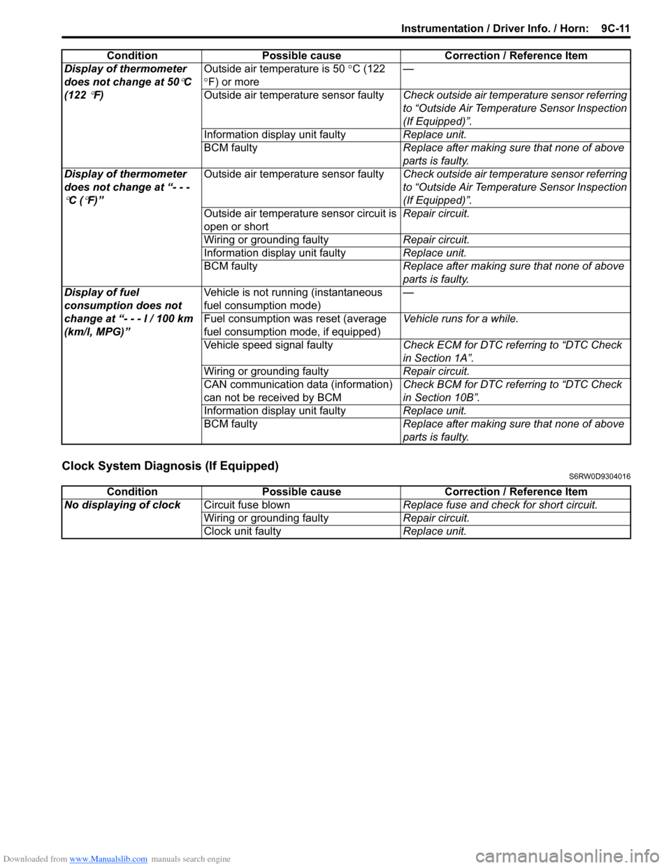
Display of fuel
consumption does not
change at “- - - l / 100 km
(km/l, MPG)”Vehicle is not running (instantaneous
fuel consumption mode)—
Fuel consumption was reset (average
fuel consumption mode, if equipped)Vehicle runs for a while.
Vehicle speed signal faultyCheck ECM for DTC referring to “DTC Check
in Section 1A”.
Wiring or grounding faultyRepair circuit.
CAN communication data (information)
can not be received by BCMCheck BCM for DTC referring to “DTC Check
in Section 10B”.
Information display unit faultyReplace unit.
BCM faultyReplace after making sure that none of above
parts is faulty. Condition Possible cause Correction / Reference Item
Condition Possible cause Correction / Reference Item
No displaying of clockCircuit fuse blownReplace fuse and check for short circuit.
Wiring or grounding faultyRepair circuit.
Clock unit faultyReplace unit.
Page 1474 of 1556

Downloaded from www.Manualslib.com manuals search engine 10B-1 Body Electrical Control System:
Control Systems
Body Electrical Control System
Precautions
Precautions in Diagnosing TroubleS6RW0DA200001
• Diagnostic information stored in BCM memory can be cleared as well as checked by using SUZUKI scan tool.
Before using scan tool, read its Operator’s (Instruction) Manual carefully to have good understanding as to what
functions are available and how to use it.
• Be sure to read “Precautions for Electrical Circuit Service in Section 00” before inspection and observe what is
written there.
• Communication of ECM, TCM (A/T model), ABS control module, 4WD control module (if equipped), keyless start
control module (if equipped), combination meter and BCM is established by CAN (Controller Area Network). For
detail of CAN communication for BCM, refer to “CAN Communication System Description”. Therefore, handle CAN
communication line with care referring to “Precaution for CAN Communication System in Section 00”.
General Description
BCM General DescriptionS6RW0DA201001
The Body electrical Control Module (BCM) is
incorporated in junction block. Do not attempt removal of
BCM from junction block as it may cause contact failure.
The BCM incorporates relays and controllers which are
used for the following systems and controls them.
• Power door lock (if equipped)
• Keyless entry (if equipped)
• Door lock function of keyless start system (if
equipped)
• Rear wiper
• Combination meter
• Interior light• Warning buzzer
• Rear end door window defogger and door mirror
heater (if equipped)
• Rear end door opener (if equipped)
• Theft deterrent light
Also, the BCM has a function to cause the interior light
and open door warning light in the combination meter to
turn off when any door is left open for longer than 15
minutes to reduce wasteful battery consumption.
In addition, it is possible to check operation of actuator
which is controlled by BCM by using the output test
function of SUZUKI scan tool to operate actuator
simulatively.
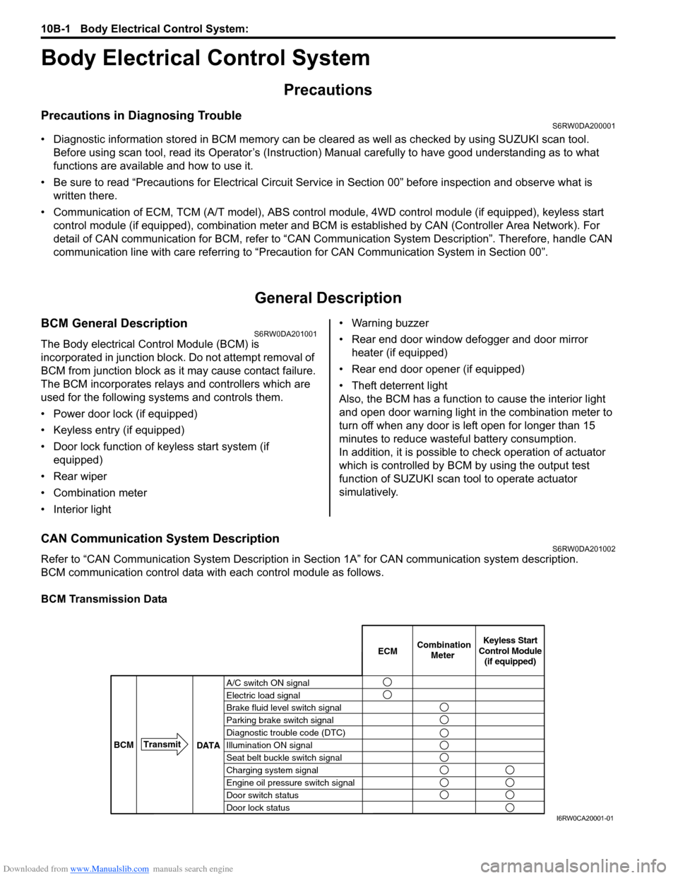
CAN Communication System DescriptionS6RW0DA201002
Refer to “CAN Communication System Description in Section 1A” for CAN communication system description.
BCM communication control data with each control module as follows.
BCM Transmission Data
A/C switch ON signal
Electric load signal
Brake fluid level switch signal
Parking brake switch signal
Diagnostic trouble code (DTC)
Illumination ON signal
Seat belt buckle switch signal
Charging system signal
Engine oil pressure switch signal
Door switch status
Door lock statusECMKeyless Start
Control Module
(if equipped) Combination
Meter
BCMTransmit
DATA
I6RW0CA20001-01