2006 SUZUKI SX4 bulb
[x] Cancel search: bulbPage 577 of 1556

Downloaded from www.Manualslib.com manuals search engine Brake Control System and Diagnosis: 4A-6
Dragging brakes (Without
a very light drag is
present in all brakes
immediately after pedal is
released)Master cylinder pistons not returning
correctlyReplace master cylinder.
Restricted brake pipes or hosesCheck for soft hoses or damaged pipes and
replace with new hoses and/or new brake
piping.
Incorrect parking brake adjustment on
rear brakesCheck and adjust to correct specifications.
Weakened or broken return springs in
the drum brakeReplace.
Sluggish parking brake cables or linkageRepair or replace.
Wheel cylinder or caliper piston stickingRepair as necessary.
Badly worn piston seal in caliperReplace piston seal.
Improper brake pedal free heightCheck brake pedal free height.
Pedal pulsation (Pedal
pulsates when depressed
for braking)Damaged wheel bearingsReplace wheel bearings.
Distorted steering knuckle or rear wheel
spindle or rear axle shaftReplace knuckle or rear wheel spindle or rear
axle shaft.
Excessive disc lateral runoutCheck per instructions. If not within
specifications, replace or machine disc.
Rear drums out of roundCheck runout.
Repair or replace drum as necessary.
Braking noiseGlazed brake pad and/or brake shoeRepair or replace brake pad and/or brake
shoe.
Worn or distorted brake shoeReplace brake shoe.
Loose front wheel bearingsReplace wheel hub.
Distorted backing plates or loose
mounting boltsReplace or retighten securing bolts.
Contact wear indicator to brake discReplace brake pads.
Brake warning light lights
after engine startParking brake appliedRelease parking brake and check that brake
warning light turns off.
Insufficient amount of brake fluidInvestigate leaky point, correct it and add
brake fluid.
Brake fluid leakingInvestigate leaky point, correct it and add
brake fluid.
Brake warning light circuit faultyRepair circuit.
Malfunctioning EBD systemCheck system referring to “EBD Warning Light
(Brake Warning Light) Comes ON Steady in
Section 4E”.
Brake warning light turns
on when brake is appliedBrake fluid leakingInvestigate leaky point, correct it and add
brake fluid.
Insufficient amount of brake fluidInvestigate leaky point, correct it and add
brake fluid.
Brake warning light fails
to turn on even when
parking brake is appliedBrake warning light circuit faultyReplace bulb or repair circuit.
ABS warning light turns
on after engine startMalfunctioning ABSCheck system referring to “ABS Check in
Section 4E”.
ABS warning light turns
on when brake is appliedMalfunctioning ABSCheck system referring to “ABS Check in
Section 4E”.
ABS warning light after
ignition switch has turned
ON Bulb burnt outReplace bulb.
Malfunctioning ABSCheck system referring to “ABS Check in
Section 4E”.
ABS warning light flashesNew ABS hydraulic unit / control module
assembly installed.Perform “ABS Hydraulic Unit Operation Check
in Section 4E”. Condition Possible cause Correction / Reference Item
Page 656 of 1556

Downloaded from www.Manualslib.com manuals search engine 5A-8 Automatic Transmission/Transaxle:
On-Board Diagnostic System DescriptionS6RW0D5101005
NOTE
There are two types of OBD system
depending on the vehicle specification.For
identification, refer to “Precaution on On-
Board Diagnostic (OBD) System in Section
1A”.
For automatic transaxle control system, TCM has the
following functions.
• For Euro OBD model, when the ignition switch is
turned ON with the engine at a stop, MIL (1) turns ON
to check the bulb of the MIL.
• For Euro OBD model, when TCM detects a
malfunction in A/T control system TCM desires turning
on MIL and stores malfunction DTC in TCM memory.
(If it detects that continuously 3 driving cycles are
normal after detecting a malfunction, however, it
makes MIL turn OFF although DTC stored in its
memory will remain.)
• For Euro OBD model, it is possible to communicate
with TCM through data link connector (DLC) (2) by
using not only SUZUKI scan tool (3) but also CAN
communication OBD generic scan tool. (Diagnostic
information can be checked and erased by using scan
tool.)
• For non-Euro-OBD model, when ignition switch is
turned ON and no malfunction in A/T control system is
detected, transmission warning light (4) lights for
about 2 seconds after ignition switch is turned ON and
then goes OFF for bulb check.• For non-Euro-OBD model, when TCM detects a
malfunction in A/T control system, it indicates
transmission warning light (4) and stores malfunction
DTC in its memory.
• For information about the following items, refer to “On-
Board Diagnostic System Description in Section 1A”.
– Warm-up cycle
– Driving cycle
– 2 driving cycle detection logic
– Pending DTC
– Freeze frame date
1
3 2
4
I6RW0B510001-01
Page 744 of 1556

Downloaded from www.Manualslib.com manuals search engine 5A-96 Automatic Transmission/Transaxle:
10) Remove valve body assembly referring to
“Automatic Transaxle Unit Disassembly”.
11) Remove pressure control solenoid valve and TCC
pressure control solenoid valve referring to “Valve
Body Assembly Disassembly and Reassembly”.
Installation
Reverse removal procedure to install pressure control
solenoid valve and valve body assembly noting the
following points.
• For detail of pressure control solenoid valve and TCC
pressure control solenoid valve installation, refer to
“Valve Body Assembly Disassembly and
Reassembly”.
• For detail of valve body assembly installation, refer to
“Automatic Transaxle Unit Assembly”.
• For detail of installing wire harness for solenoid valves
and sensor, refer to “Automatic Transaxle Unit
Assembly”. Use new O-rings.
• For detail of A/T oil pan and oil strainer assembly
installation, refer to “Automatic Transaxle Unit
Assembly”. Use new oil pan gasket.
• Pour A/T fluid and check fluid level according to
procedure described in “A/T Fluid Change”.
• Check for fluid leakage after warming up A/T.
Pressure Control Solenoid Valves InspectionS6RW0D5106020
CAUTION!
• Be very careful as dust etc. does enter
when pressure control solenoid valves are
inspected.
Resistance Check
Measure resistance between pressure control solenoid
valves (Pressure control solenoid and TCC pressure
control solenoid) (1) terminals.
Pressure control solenoid valve and TCC pressure
control solenoid valve resistance
Standard: 5.0 – 5.6 Ω at 20 °C (68 °F)Operation Check
Check pressure control solenoid valves (Pressure
control solenoid and TCC pressure control solenoid)
operation in the either manner of the following.
Using regulated DC power supply
1) Connect pressure control solenoid valve (1) with
regulated DC power supply (2) as shown in figure.
2) Turn regulated DC power supply switch ON and
increase voltage of power supply keeping current
within 1.0 A.
3) Check for gradual movement of valve (3) in the
direction of arrow “A” as voltage is increased.
4) Check movement of valve (3) in the direction of
arrow “B” as voltage is decreased.
5) Turn power supply switch OFF.
CAUTION!
Do not pass current 1.0 A or more, or
pressure control solenoid is burned out.
Not using regulated DC power supply
1) Connect pressure control solenoid valve (1) to
battery (2) setting 21 W bulb (4) on the way as
shown in figure.
2) Check for movement of valve (3) in the direction of
arrow “A”.
3) Disconnect pressure control solenoid valve (1) from
battery (2) and check movement of valve (3) in the
direction of arrow “B” as shown in figure.
CAUTION!
Set 21 W bulb on the way, or pressure control
solenoid valve is burned out.
1
I2RH01510071-01
I2RH0B510064-01
Page 934 of 1556

Downloaded from www.Manualslib.com manuals search engine 7A-6 Heater and Ventilation:
Blower Motor Relay InspectionS6RW0D7106007
1) Disconnect negative (–) cable at battery.
2) Disable air bag system referring to “Disabling Air
Bag System in Section 8B”.
3) Remove junction block assembly (2).
4) Disconnect blower motor relay (1) from junction
block assembly (2).
5) Check that there is no continuity between terminal
“C” and “D”. If there is continuity, replace relay.
6) Connect battery positive (+) terminal to terminal “B”
of relay. Connect battery negative (–) terminal “A” of
relay.
Check continuity between terminal “C” and “D”.
If there is no continuity when relay is connected to
the battery, replace relay.
HVAC Control Unit ComponentsS6RW0D7106008
“D” “B”“A”“C”
1
2
I4RS0B710008-01
1. Heater control body assembly 4. Bulb 7. Air intake selector 10. Rear defogger switch
2. Air flow selector 5. Temperature control cable 8. Temperature selector
3. Blower speed selector 6. Air flow control cable 9. A/C switch (if equipped)
7
10
9
2
3 8
45
61
I5RW0A710005-01
Page 948 of 1556

Downloaded from www.Manualslib.com manuals search engine 7B-8 Air Conditioning System: Manual Type
Diagnostic Information and Procedures
A/C System Performance InspectionS6RW0D7214001
1) Confirm that vehicle and environmental conditions
are as follows.
• Vehicle is put indoors.
• Ambient temperature is within 25 – 35 °C (77 – 95
°F).
• Relative humidity is within 30 – 70%.
• There is no wind indoors.
• HVAC unit is normal.
• Blower motor is normal.
• There is no air leakage from air ducts.
• Condenser fins are clean.
• HVAC air filter is not clogged with dirt and dust (if
equipped).
• Battery voltage is about 12 V.
• Radiator cooling fan operates normally.
2) Make sure that high pressure valve (1) and low
pressure valve (2) of manifold gauge are firmly
closed.
3) Connect high pressure charging hose (3) to high
pressure service valve (5) on vehicle and low
pressure charging hose (4) to low pressure service
valve (6).
4) Bleed the air in charging hoses (3) and (4) by
loosening their nuts respectively utilizing the
refrigerant pressure. When a hissing sound is heard,
immediately tighten nut.
CAUTION!
Do not connect high and low pressure
charging hoses in reverse.
5) Warm up engine to the normal operating
temperature and keep it at the specified idle speed.
6) Turn A/C switch ON, set blower speed selector at
maximum speed position, temperature selector at
maximum cold position, air flow selector at face
position, and air intake selector at recirculation
position. (Confirm that A/C compressor, A/C
condenser cooling fan and radiator cooling fan are
working.)
7) Wait for ten minutes to stabilize the A/C operation.
8) Open all door windows, front doors and engine hood.
9) With about 20 mm (0.8 in.) of dry bulb thermometer
(1) put right in front of center ventilation louver and a
wet and dry bulb thermometer (2) near air inlet of
HVAC unit.
321
4
6
5
I7RW01721006-01
2
1
I5RW0A721008-01
Page 1025 of 1556

Downloaded from www.Manualslib.com manuals search engine Air Conditioning System: Automatic Type 7B-85
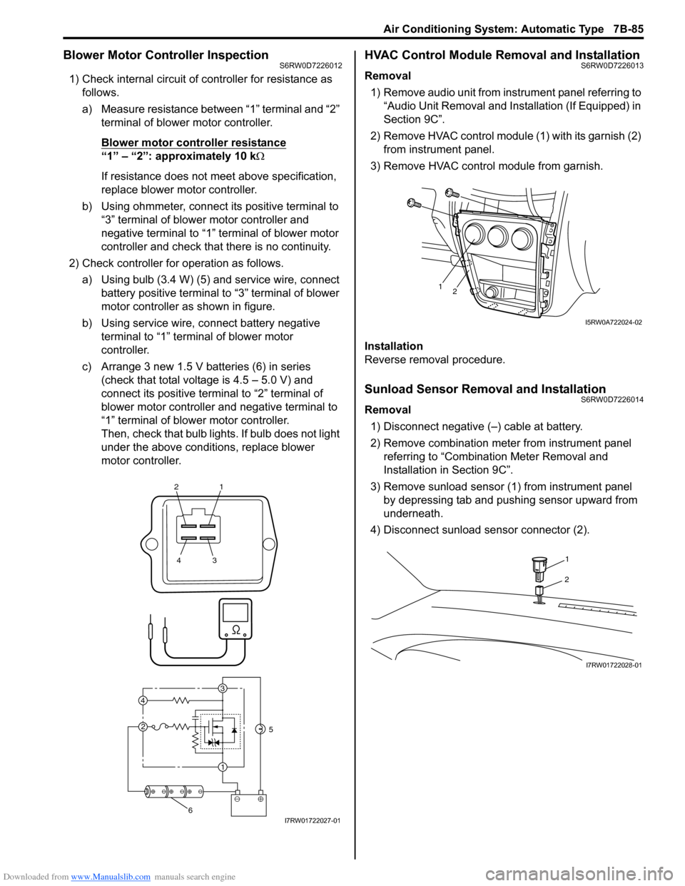
Blower Motor Controller InspectionS6RW0D7226012
1) Check internal circuit of controller for resistance as
follows.
a) Measure resistance between “1” terminal and “2”
terminal of blower motor controller.
Blower motor controller resistance
“1” – “2”: approximately 10 kΩ
If resistance does not meet above specification,
replace blower motor controller.
b) Using ohmmeter, connect its positive terminal to
“3” terminal of blower motor controller and
negative terminal to “1” terminal of blower motor
controller and check that there is no continuity.
2) Check controller for operation as follows.
a) Using bulb (3.4 W) (5) and service wire, connect
battery positive terminal to “3” terminal of blower
motor controller as shown in figure.
b) Using service wire, connect battery negative
terminal to “1” terminal of blower motor
controller.
c) Arrange 3 new 1.5 V batteries (6) in series
(check that total voltage is 4.5 – 5.0 V) and
connect its positive terminal to “2” terminal of
blower motor controller and negative terminal to
“1” terminal of blower motor controller.
Then, check that bulb lights. If bulb does not light
under the above conditions, replace blower
motor controller.
HVAC Control Module Removal and InstallationS6RW0D7226013
Removal
1) Remove audio unit from instrument panel referring to
“Audio Unit Removal and Installation (If Equipped) in
Section 9C”.
2) Remove HVAC control module (1) with its garnish (2)
from instrument panel.
3) Remove HVAC control module from garnish.
Installation
Reverse removal procedure.
Sunload Sensor Removal and InstallationS6RW0D7226014
Removal
1) Disconnect negative (–) cable at battery.
2) Remove combination meter from instrument panel
referring to “Combination Meter Removal and
Installation in Section 9C”.
3) Remove sunload sensor (1) from instrument panel
by depressing tab and pushing sensor upward from
underneath.
4) Disconnect sunload sensor connector (2).
21
43
3
1 2 4
5
6I7RW01722027-01
12
I5RW0A722024-02
1
2
I7RW01722028-01
Page 1163 of 1556

Downloaded from www.Manualslib.com manuals search engine Table of Contents 9-iii
Headlight Bulb Replacement (Discharge
Headlight Model) ............................................. 9B-19
Ballast Removal and Installation (Discharge
Headlight Model) ............................................. 9B-19
Igniter Removal and Installation (Discharge
Headlight Model) ............................................. 9B-20
Headlight Aiming Adjustment with Screen ........ 9B-20
Headlight Switch (in Lighting Switch)
Removal and Installation................................. 9B-22
Headlight Switch (in Lighting Switch)
Inspection........................................................ 9B-22
Hazard Warning Switch Removal and
Installation ....................................................... 9B-23
Hazard Warning Switch Inspection ................... 9B-23
Brake Light Switch Inspection ........................... 9B-23
Turn Signal Light Switch (in Lighting Switch)
Removal and Installation................................. 9B-24
Turn Signal Light Switch (in Lighting Switch)
Inspection........................................................ 9B-24
Turn Signal and Hazard Warning Relay
Removal and Installation................................. 9B-24
Turn Signal and Hazard Warning Relay
Inspection........................................................ 9B-25
License Light Assembly Removal and
Installation ....................................................... 9B-25
Front Fog Light Assembly Removal and
Installation (If Equipped) ................................. 9B-26
Front Fog Light Switch Inspection (If
Equipped)........................................................ 9B-26
Front Fog Light Aiming Adjustment with
Screen (If Equipped) ....................................... 9B-26
Rear Fog Light Switch Inspection (If
Equipped)........................................................ 9B-27
Headlight Manual Levering Switch Inspection
(If Equipped) ................................................... 9B-28
Headlight Leveling Actuator Inspection (If
Equipped)........................................................ 9B-28
Height Sensor Removal and Installation (If
Equipped)........................................................ 9B-29
Height Sensor and Its Circuit Inspection (If
Equipped)........................................................ 9B-30
Headlight Leveling Control Module Removal
and Installation (If Equipped) .......................... 9B-30
Initialization of Headlight Auto Leveling
System ............................................................ 9B-30
Auto-On Headlight Sensor Inspection (If
Equipped)........................................................ 9B-31
Illumination Cancel Switch Inspection (If
Equipped)........................................................ 9B-32
Tail Light Relay, Headlight Relay, Front Fog
Light Relay Inspection (If Equipped) ............... 9B-32
Specifications..................................................... 9B-33
Tightening Torque Specifications ...................... 9B-33
Instrumentation / Driver Info. / Horn ...... 9C-1
Precautions........................................................... 9C-1
Precautions in Diagnosing Troubles for
Combination Meter............................................ 9C-1
General Description ............................................. 9C-1
CAN Communication System Description........... 9C-1Auto Volume Control System Description (If
Equipped) ..........................................................9C-3
Schematic and Routing Diagram ........................9C-4
Combination Meter Circuit Diagram ....................9C-4
Component Location ...........................................9C-5
Audio System Component Location ....................9C-5
Diagnostic Information and Procedures ............9C-6
Speedometer and VSS Symptom Diagnosis ......9C-6
Tachometer Symptom Diagnosis ........................9C-6
Engine Coolant Temperature (ECT) Meter
Symptom Diagnosis ..........................................9C-6
Fuel Meter Symptom Diagnosis ..........................9C-6
Low Fuel Warning Light Symptom Diagnosis .....9C-7
Oil Pressure Warning Light Symptom
Diagnosis ..........................................................9C-7
Brake and Parking Brake Warning Light
Symptom Diagnosis ..........................................9C-8
Seat Belt Reminder Light Symptom Diagnosis ....9C-8
A/T Shift Position Indicator Symptom
Diagnosis (A/T Model).......................................9C-8
Charge Warning Light Symptom Diagnosis ........9C-9
Main Beam (High Beam) Indicator Symptom
Diagnosis ..........................................................9C-9
Warning Buzzer Circuit Symptom Diagnosis ......9C-9
Cigarette Lighter Symptom Diagnosis (If
Equipped) ........................................................9C-10
Horn Symptom Diagnosis .................................9C-10
Information Display Symptom Diagnosis (If
Equipped) ........................................................9C-10
Clock System Diagnosis (If Equipped) ..............9C-11
Audio System Symptom Diagnosis (If
Equipped) ........................................................9C-12
Remote Audio Control Switch Symptom
Diagnosis (If Equipped) ...................................9C-13
Navigation Symptom Diagnosis (If Equipped)...9C-13
Repair Instructions ............................................9C-14
Ignition Switch Removal and Installation...........9C-14
Ignition Switch Inspection..................................9C-14
Combination Meter Removal and Installation ...9C-14
Fuel Level Sensor Removal and Installation .....9C-15
Fuel Level Sensor Inspection ............................9C-15
Oil Pressure Switch Removal and Installation ..9C-15
Oil Pressure Switch Inspection .........................9C-15
Engine Coolant Temperature (ECT) Sensor
Inspection ........................................................9C-16
Brake Fluid Level Switch Inspection .................9C-16
Parking Brake Switch Inspection.......................9C-16
Door Switch (Front / Rear Door) Inspection ......9C-16
Rear End Door Switch Inspection .....................9C-16
Outside Air Temperature Sensor Removal
and Installation (If Equipped) ..........................9C-17
Outside Air Temperature Sensor Inspection
(If Equipped)....................................................9C-17
Instrument Panel Removal and Installation.......9C-17
Information Display (Clock) Removal and
Installation .......................................................9C-18
Audio Unit Removal and Installation (If
Equipped) ........................................................9C-19
Page 1169 of 1556

Downloaded from www.Manualslib.com manuals search engine Wiring Systems: 9A-2
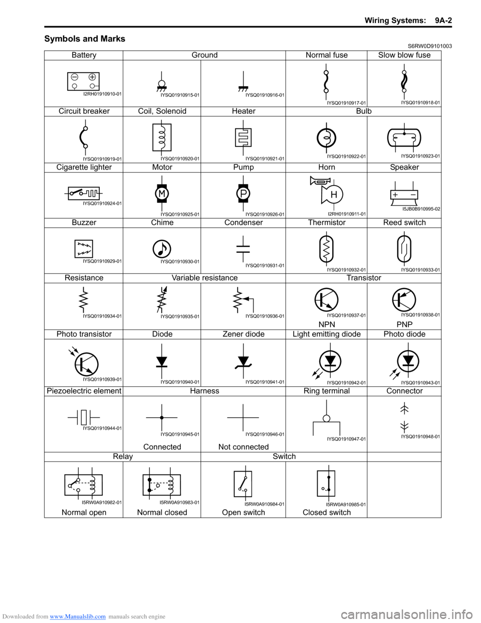
Symbols and MarksS6RW0D9101003
Battery Ground Normal fuse Slow blow fuse
Circuit breaker Coil, Solenoid Heater Bulb
Cigarette lighter Motor Pump Horn Speaker
Buzzer Chime Condenser Thermistor Reed switch
Resistance Variable resistance Transistor
NPN PNP
Photo transistor Diode Zener diode Light emitting diode Photo diode
Piezoelectric element Harness Ring terminal Connector
Connected Not connected
Relay Switch
Normal open Normal closed Open switch Closed switch
I2RH01910910-01IYSQ01910915-01IYSQ01910916-01
IYSQ01910917-01IYSQ01910918-01
IYSQ01910919-01IYSQ01910920-01IYSQ01910921-01IYSQ01910922-01IYSQ01910923-01
IYSQ01910924-01
IYSQ01910925-01IYSQ01910926-01
H
I2RH01910911-01I5JB0B910995-02
IYSQ01910929-01IYSQ01910930-01IYSQ01910931-01IYSQ01910932-01IYSQ01910933-01
IYSQ01910934-01IYSQ01910935-01IYSQ01910936-01IYSQ01910937-01IYSQ01910938-01
IYSQ01910939-01IYSQ01910940-01IYSQ01910941-01IYSQ01910942-01IYSQ01910943-01
IYSQ01910944-01IYSQ01910945-01IYSQ01910946-01IYSQ01910947-01IYSQ01910948-01
I5RW0A910982-01I5RW0A910983-01I5RW0A910984-01I5RW0A910985-01