2006 SUZUKI SX4 door lock
[x] Cancel search: door lockPage 1195 of 1556
Downloaded from www.Manualslib.com manuals search engine Wiring Systems: 9A-28
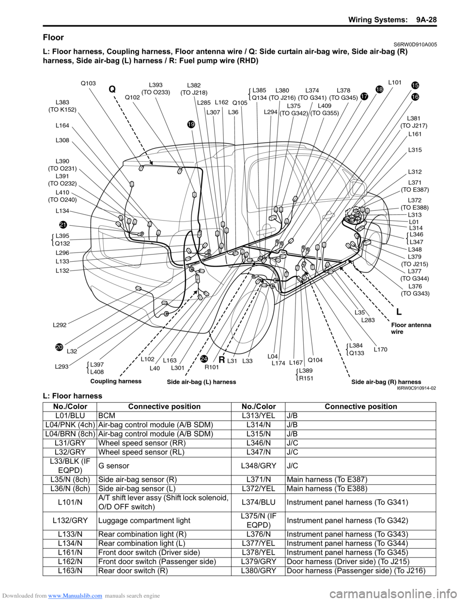
FloorS6RW0D910A005
L: Floor harness, Coupling harness, Floor antenna wire / Q: Side curtain air-bag wire, Side air-bag (R)
harness, Side air-bag (L) harness / R: Fuel pump wire (RHD)
L: Floor harness
21
20
24
19
171815
16L383
(TO K152)
L390
(TO O231)
L391
(TO O232)
L164
L134
L397
L408
L292
L293
L32
L132
L133
L296L381
(TO J217)
L375
(TO G342)
L374
(TO G341)L380
(TO J216)L378
(TO G345)
L161
L283
L35
L36
L301
Q105
R101
L102
L40
L294
L31L174L33L167Q104L04
Q103L382
(TO J218)
L376
(TO G343)
L170
L379
(TO J215)
L371
(TO E387)
L372
(TO E388)
L377
(TO G344)
Q102L162L285
L163
L101
L348
L314
L315
L312
L313
L01
L395
Q132
L385
Q134L393
(TO O233)
L346
L347
L389
R151
L384
Q133
L
R Q
Coupling harness
Side air-bag (R) harnessFloor antenna
wire
Side air-bag (L) harness
L410
(TO O240)
L308L307
L409
(TO G355)
I6RW0C910914-02
No./Color Connective position No./Color Connective position
L01/BLU BCM L313/YEL J/B
L04/PNK (4ch) Air-bag control module (A/B SDM) L314/N J/B
L04/BRN (8ch) Air-bag control module (A/B SDM) L315/N J/B
L31/GRY Wheel speed sensor (RR) L346/N J/C
L32/GRY Wheel speed sensor (RL) L347/N J/C
L33/BLK (IF
EQPD)G sensor L348/GRY J/C
L35/N (8ch) Side air-bag sensor (R) L371/N Main harness (To E387)
L36/N (8ch) Side air-bag sensor (L) L372/YEL Main harness (To E388)
L101/NA/T shift lever assy (Shift lock solenoid,
O/D OFF switch)L374/BLU Instrument panel harness (To G341)
L132/GRY Luggage compartment lightL375/N (IF
EQPD)Instrument panel harness (To G342)
L133/N Rear combination light (R) L376/N Instrument panel harness (To G343)
L134/N Rear combination light (L) L377/YEL Instrument panel harness (To G344)
L161/N Front door switch (Driver side) L378/YEL Instrument panel harness (To G345)
L162/N Front door switch (Passenger side) L379/GRY Door harness (Driver side) (To J215)
L163/N Rear door switch (R) L380/GRY Door harness (Passenger side) (To J216)
Page 1197 of 1556
Downloaded from www.Manualslib.com manuals search engine Wiring Systems: 9A-30
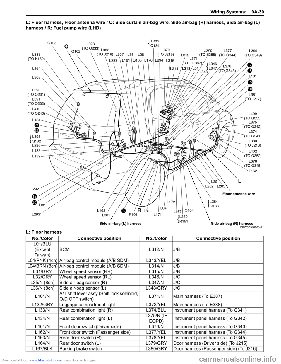
L: Floor harness, Floor antenna wire / Q: Side curtain air-bag wire, Side air-bag (R) harness, Side air-bag (L)
harness / R: Fuel pump wire (LHD)
L: Floor harness
21
22
20
24
19
17
18
15
16
L383
(TO K152)
L390
(TO O231)
L391
(TO O232)
L410
(TO O240)
L164
L308
L134
L292
L293
L32
L132
L133
L296L381
(TO J217)
L375
(TO G342)
L402
(TO G352)
L374
(TO G341)L409
(TO G355)
L380
(TO J216)
L378
(TO G345)
L162
L285L282
L35
L36L281 L307
L301
Q105
R101L171
L294 L170
L31L167Q104L04
L172
Q103
L382
(TO J218)
L376
(TO G343)L379
(TO J215)
L371
(TO E387)
L372
(TO E388)L377
(TO G344)Q102
L161L283
L163
L101L348
L399
(TO G349)
L314
L315
L312
L313
L01
L395
Q132
L385
Q134L393
(TO O233)
L346
L347
L389
R151
L384
Q133
L
R Q
Side air-bag (R) harnessFloor antenna wire
Side air-bag (L) harnessI6RW0D910903-01
No./Color Connective position No./Color Connective position
L01/BLU
(Except
Ta i w a n )BCM L312/N J/B
L04/PNK (4ch) Air-bag control module (A/B SDM) L313/YEL J/B
L04/BRN (8ch) Air-bag control module (A/B SDM) L314/N J/B
L31/GRY Wheel speed sensor (RR) L315/N J/B
L32/GRY Wheel speed sensor (RL) L346/N J/C
L35/N (8ch) Side air-bag sensor (R) L347/N J/C
L36/N (8ch) Side air-bag sensor (L) L348/GRY J/C
L101/NA/T shift lever assy (Shift lock solenoid,
O/D OFF switch)L371/N Main harness (To E387)
L132/GRY Luggage compartment light L372/YEL Main harness (To E388)
L133/N Rear combination light (R) L374/BLU Instrument panel harness (To G341)
L134/N Rear combination light (L)L375/N (IF
EQPD)Instrument panel harness (To G342)
L161/N Front door switch (Driver side) L376/N Instrument panel harness (To G343)
L162/N Front door switch (Passenger side) L377/YEL Instrument panel harness (To G344)
L163/N Rear door switch (R) L378/YEL Instrument panel harness (To G345)
L164/N Rear door switch (L) L379/GRY Door harness (Driver side) (To J215)
L167/BLK Parking brake switch L380/GRY Door harness (Passenger side) (To J216)
Page 1224 of 1556
Downloaded from www.Manualslib.com manuals search engine 9A-57 Wiring Systems:
System Circuit Diagram
System Circuit DiagramS6RW0D910E001
Refer to “A-1 Cranking System Circuit Diagram”.
Refer to “A-2 Charging System Circuit Diagram”.
Refer to “A-3 Ignition System Circuit Diagram (M15A engine, M16A engine)”.
Refer to “A-3 Ignition System Circuit Diagram (J20A engine)”.
Refer to “A-4 Cooling System Circuit Diagram (M15A engine, M16A engine)”.
Refer to “A-4 Cooling System Circuit Diagram (J20A engine)”.
Refer to “A-5 Engine and A/C Control System Circuit Diagram (M15A engine)”.
Refer to “A-5 Engine and A/C Control System Circuit Diagram (M16A engine)”.
Refer to “A-5 Engine and A/C Control System Circuit Diagram (J20A engine)”.
Refer to “A-6 A/T Control System Circuit Diagram”.
Refer to “A-7 Immobilizer System Circuit Diagram”.
Refer to “A-8 Body Control System Circuit Diagram (Except Taiwan)”.
Refer to “A-8 Body Control System Circuit Diagram (Taiwan)”.
Refer to “A-10 4WD Control System (Except Taiwan)”
Refer to “B-1 Windshield Wiper and Washer Circuit Diagram”.
Refer to “B-2 Rear Wiper and Washer Circuit Diagram (Except Taiwan)”.
Refer to “B-2 Rear Wiper and Washer Circuit Diagram (Taiwan)”.
Refer to “B-3 Rear Defogger Circuit Diagram (Except Taiwan)”.
Refer to “B-3 Rear Defogger Circuit Diagram (Taiwan)”.
Refer to “B-4 Power Window Circuit Diagram”.
Refer to “B-5 Power Door Lock Circuit Diagram (Except Taiwan)”.
Refer to “B-5 Power Door Lock Circuit Diagram (Taiwan)”.
Refer to “B-6 Power Mirror Circuit Diagram (Except Taiwan)”.
Refer to “B-6 Power Mirror Circuit Diagram (Taiwan)”.
Refer to “B-7 Horn Circuit Diagram”.
Refer to “B-8 Seat Heater Circuit Diagram”.
Refer to “B-9 Keyless Start System Circuit Diagram”
Refer to “C-1 Combination Meter Circuit Diagram (Meter)”.
Refer to “C-2 Combination Meter Circuit Diagram (Indicator)”.
Refer to “C-3 Combination Meter Circuit Diagram (Warning Light)”.
Refer to “D-1 Headlight System Circuit Diagram (Except Taiwan)”.
Refer to “D-1 Headlight System Circuit Diagram (Taiwan)”.
Refer to “D-2 Position, Tail and Licence Plate Light System Circuit Diagram (Except Taiwan)”.
Refer to “D-2 Position, Tail and Licence Plate Light System Circuit Diagram (Taiwan)”.
Refer to “D-3 Front Fog Light System Circuit Diagram (Except Taiwan)”.
Refer to “D-3 Front Fog Light System Circuit Diagram (Taiwan)”.
Refer to “D-4 Illumination Light System Circuit Diagram (Except Taiwan)”.
Refer to “D-4 Illumination Light System Circuit Diagram (Taiwan)”.
Refer to “D-5 Interior Light System Circuit Diagram (Except Taiwan)”.
Refer to “D-5 Interior Light System Circuit Diagram (Taiwan)”.
Refer to “D-6 Turn Signal and Hazard Warning Light System Circuit Diagram (Except Taiwan)”.
Refer to “D-6 Turn Signal and Hazard Warning Light System Circuit Diagram (Taiwan)”.
Refer to “D-7 Brake Light System Circuit Diagram”.
Refer to “D-8 Back-Up Light System Circuit Diagram”.
Refer to “D-9 Headlight Beam Leveling System Circuit Diagram (Manual Leveling)”.
Refer to “D-10 Rear Fog Light Circuit Diagram”.
Refer to “E-1 Heater System Circuit Diagram”.
Refer to “E-2 Auto A/C System Circuit Diagram”.
Refer to “F-1 Air-Bag System Circuit Diagram (4ch)”.
Refer to “F-1 Air-Bag System Circuit Diagram (8ch)”.
Refer to “F-2 Anti-Lock Brake System Circuit Diagram”.
Refer to “F-4 Power Steering System Circuit Diagram”.
Refer to “G-1 Audio System Circuit Diagram”.
Refer to “G-2 Multi Information Display / Accessory Socket System Circuit Diagram”.
Refer to “G-4 Navigation System Circuit Diagram”.
Page 1248 of 1556
Downloaded from www.Manualslib.com manuals search engine 9A-81 Wiring Systems:
1817
GRN/WHTGRN/YEL
"E-1"
"E-2"
Mode control
switch
Auto
unit
G04 L01
"B-5""B-5""B-5""B-5"
11
9
L346
10
B E E
Rear
GRN
GRN
RED/BLU
GRNRED/BLU
B
L347
RED/BLUGRNRED/BLU
GRN
RED/BLU
B 1
10
B E
GRN/REDRED/BLU
BLU/YELGRN
Rear end
4
WHT/RED
Rear end
door lock
switch
3 D
D F
"D-5"
BLK/YEL
L01
Diode #2
BY
GWGYWR
G04
L31515
PPL
PPL
P
PPL
P
PPL
P
BYGRRBGGRBGRBGRB
"B-5"
Audio J/B
"G-1"Navigation
"G-4"
SolenoidMotor (R)
"B-5"
Rear
Motor (L)
J/CIF EQPDJ/C
"B-3"
Mode control
switch
BCM
BLK/YEL
BY
BLK/YEL
"D-5"Solenoid
Rear end
J/C
J/C
L346
L347
"B-3"
Auto
unit
G352
L40221211
P/S
Cont.M
"F-4"
24A23
J/B side connector (BCM) A
I6RW0C910953-02
Page 1252 of 1556
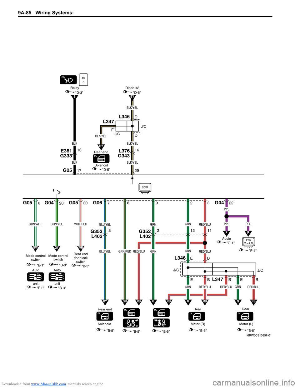
Downloaded from www.Manualslib.com manuals search engine 9A-85 Wiring Systems:
620
GRN/WHTGRN/YEL
"E-1"
"E-2"
Mode control
switch
Auto
unit
G05 G04 G05 G06
"B-5""B-5""B-5""B-5"
72
L346
3
B E E
Rear
GRN
GRN
RED/BLU
GRNRED/BLU
B
L347
RED/BLUGRNRED/BLU
GRN
RED/BLU
B 9
8
B E
GRN/REDRED/BLUBLU/YEL
BLU/YELGRN
Rear end
30
WHT/RED
Rear end
door lock
switch
29 D
D F
"D-5"
BLK/YEL
BLK/YEL
G05
Diode #2 Relay
BY
GWGYWR
G0422
PPL
PPL
P
PPL
P
BYGRRBGGRBGRBGRB
"B-5"
Audio
"G-1"
SolenoidMotor (R)
"B-5"
Rear
Motor (L)
J/CJ/C
"B-3"
Mode control
switch
BCM
BLK/YEL
BY
BLK/YEL
"D-5"Solenoid
Rear end
J/C
J/C
L346
L347
"B-3"
Auto
unit
L376
G34316
17
"D-3"
BLK
BLK
B
E381
G33313
G352
L4023G352
L40221211
P/S
Cont.M
"F-4"
I6RW0C910957-01
Page 1262 of 1556
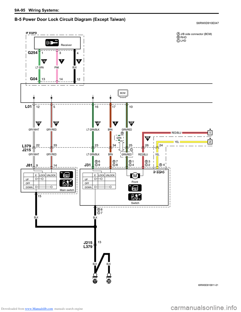
Downloaded from www.Manualslib.com manuals search engine 9A-95 Wiring Systems:
B-5 Power Door Lock Circuit Diagram (Except Taiwan)S6RW0D910E047
17 16
23
34
Switch
J31 L379
J215
BLK
Main switch
13 14 95 12
22
33
J81
BLK
BLK
BRNLT GRN/BLKGRY/REDGRY/WHT
17
BLK
20
UP
OFF
DOWNLOCK UNLOCK
E
Receiver
G254
G04
L01
LT GRNPNK
14 13
12 3 1
4
UP
OFF
DOWNLOCK UNLOCK
E
J215
L379
15
M
BRNLT GRN/BLKGRY/REDGRY/WHTGRN/RED
GRN/RED
BCM
RED/BLU
RED/BLU1
YEL22526
10
LgBBGRGWGR
RB
LgPB
Front
BLK
IF EQPD
IF EQPDJ/B side connector (BCM)
RHD
LHD A
BC
8
7BC
6
9BC7
8BC1
4B
C
GRN
B
C3
2BC
YEL
24
4B
I6RW0D910911-01
Page 1264 of 1556
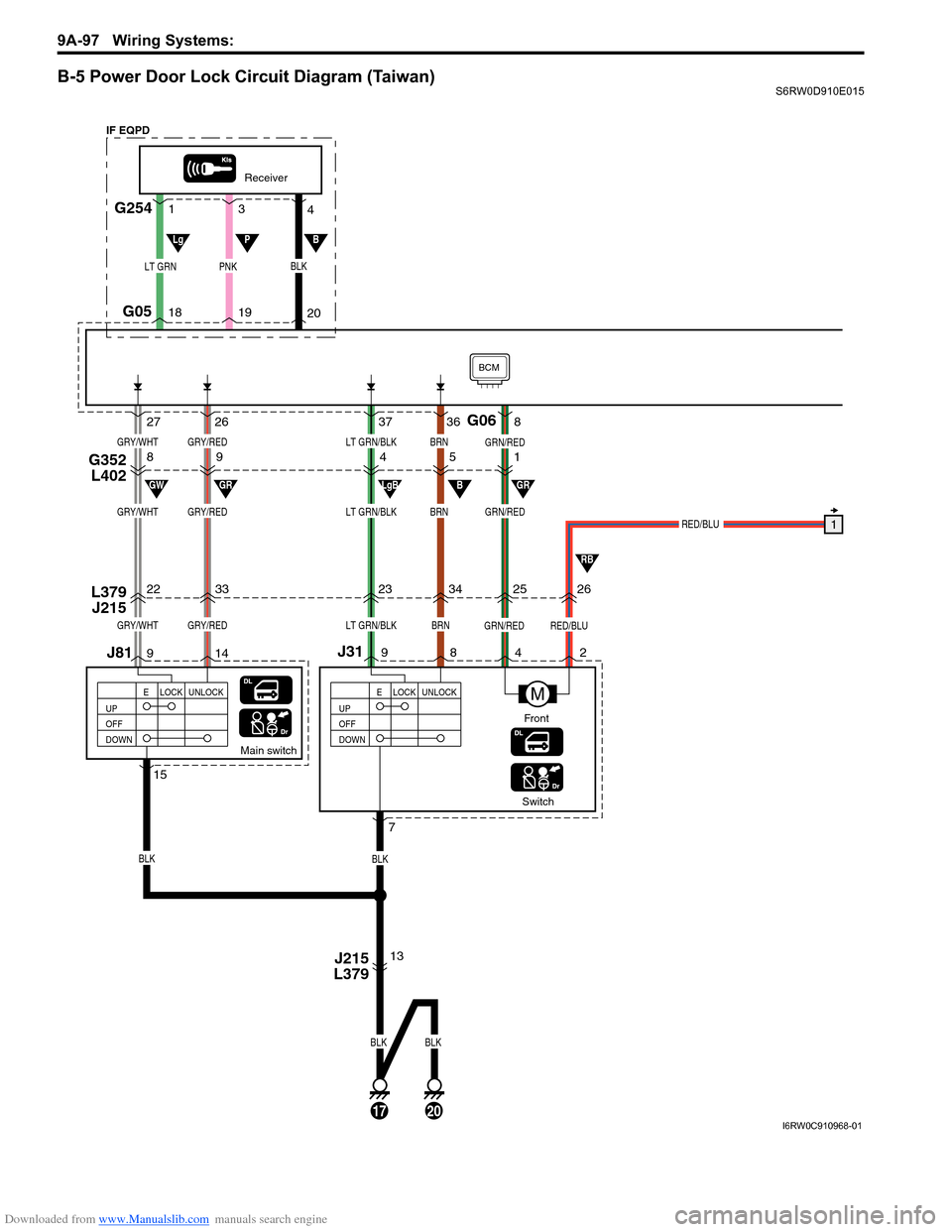
Downloaded from www.Manualslib.com manuals search engine 9A-97 Wiring Systems:
B-5 Power Door Lock Circuit Diagram (Taiwan)S6RW0D910E015
36 37
23
34
Switch
J31 L379
J215
BRN
BLK
LT GRN/BLK
Main switch
13 14 926 27
22
33
G352
L40289451
J81
GRY/RED
BLK
BLK
GRY/WHT
BRNLT GRN/BLKGRY/REDGRY/WHT
17
BLK
20
UP
OFF
DOWNLOCK UNLOCK
E
Receiver
G254
G05
G06
LT GRNPNK
19 18
20 3 1
4
UP
OFF
DOWNLOCK UNLOCK
E
J215
L379
15
M
GRN/RED
BRNLT GRN/BLKGRY/REDGRY/WHTGRN/RED
GRN/RED
BCM
RED/BLU
RED/BLU1
2526
8
LgBBGRGWGR
RB
LgPB
Front
BLK
7 9842
IF EQPD
I6RW0C910968-01
Page 1270 of 1556

Downloaded from www.Manualslib.com manuals search engine 9A-103 Wiring Systems:
B-9 Keyless Start System Circuit DiagramS6RW0D910E018
G271
KLS
ECM
BCM
WHT/RED
WHT/REDWHT/REDWHT/RED
BLU/YEL
WHTRED
WHTRED
ORN
BLU/YEL
"A-8"
W
WR
R
G1614 3420
1819
BLK/ORN
BLK/ORN
9
5
J/B
15ADOME
37
G2728 10ABACK
21
11 15AACC2
24
B
B
BB
J/C J/C
G308BG307
B
A
A
J/C
BLU/WHT
BLU/WHT
C
C
J/C
G307
Main switch
(Key switch)
STEARING
LOCK PUSH
SWITCH
G146456
1
O1223
4
2
BRN29
BRN/YEL
301011
RED/BLK
RED/BLK
B
B
J/C
Rear end
door
request
switch
G306
15ORN
ORN
ORN
1BLK/YEL
WHT/RED
378
STEARING
LOCK UNIT
Door antenna
L375
G34219
J215
L379J15317
2
L391
O2321 12
BLU
BLU
BLU
2
9
18
WHT/BLK
WHT/BLK6
Inside
antenna
6
12
GRN
GRN
5
16
LT GRN
LT GRN8
Luggage
antenna
5
12
GRN/WHT
GRN/WHT
7
15
BLK/YEL
BLK/YEL
BLK/YEL
23
Door antenna
18
J216
L380J154 L294 L293
WHT/GRN
WHT/GRN4
Rear end
antenna
7
12
RED/BLU
RED/BLU
3
17
L292
1712
WHT/BLU
WHT/BLU
WHT/BLU
24
8
18
G307
A
A
J/C
B
BG311
A
A
J/C
G309
13
YEL
YEL
YEL
BLK
BLKBLK
32
J862
1
Request
switch
13
15
BLU/RED
BLU/RED
BLU/RED
36
2321
J32
Actuator
state
switch
14
L380
J21616
7
PNK/BLK
PNK/BLK
PNK/BLK
BLK/ORNBLK/ORN
BLK/ORN
BLK/ORN
37
16
J216
L380
J852
1
Request
switch
3
15
PPL
PPL
PPL
16
J31
Actuator
state
switch
4
L379
J215 G342
L37516
O231
L390213
GRY/BLU
GRY/BLU
GRY/BLU
BLKBLK
BLK
A
A
J/C
L348
33
17
BLK
20
J215
L379
(CAN)
(CAN)
RHD
LHD AB
10
5AB
8
7AB
5
10AB
7
8AB
I6RW0C910972-01