Page 1274 of 1556
Downloaded from www.Manualslib.com manuals search engine 9A-107 Wiring Systems:
GEAR
ABS
BELT
DOOR
CHARGE
CHECK ENGINEAIRBAG
OILDRLD/F LOCK4WD AUTO
SETCRUISEIMMOBI
BRAKE
FUEL
DOME
15A37
32 5
WHT/RED
WHT/RED
J/B
G271
G241
1
2
J/C
G308B
B
IF EQPD
I6RW0C910976-01
Page 1326 of 1556
Downloaded from www.Manualslib.com manuals search engine 9B-7 Lighting Systems:
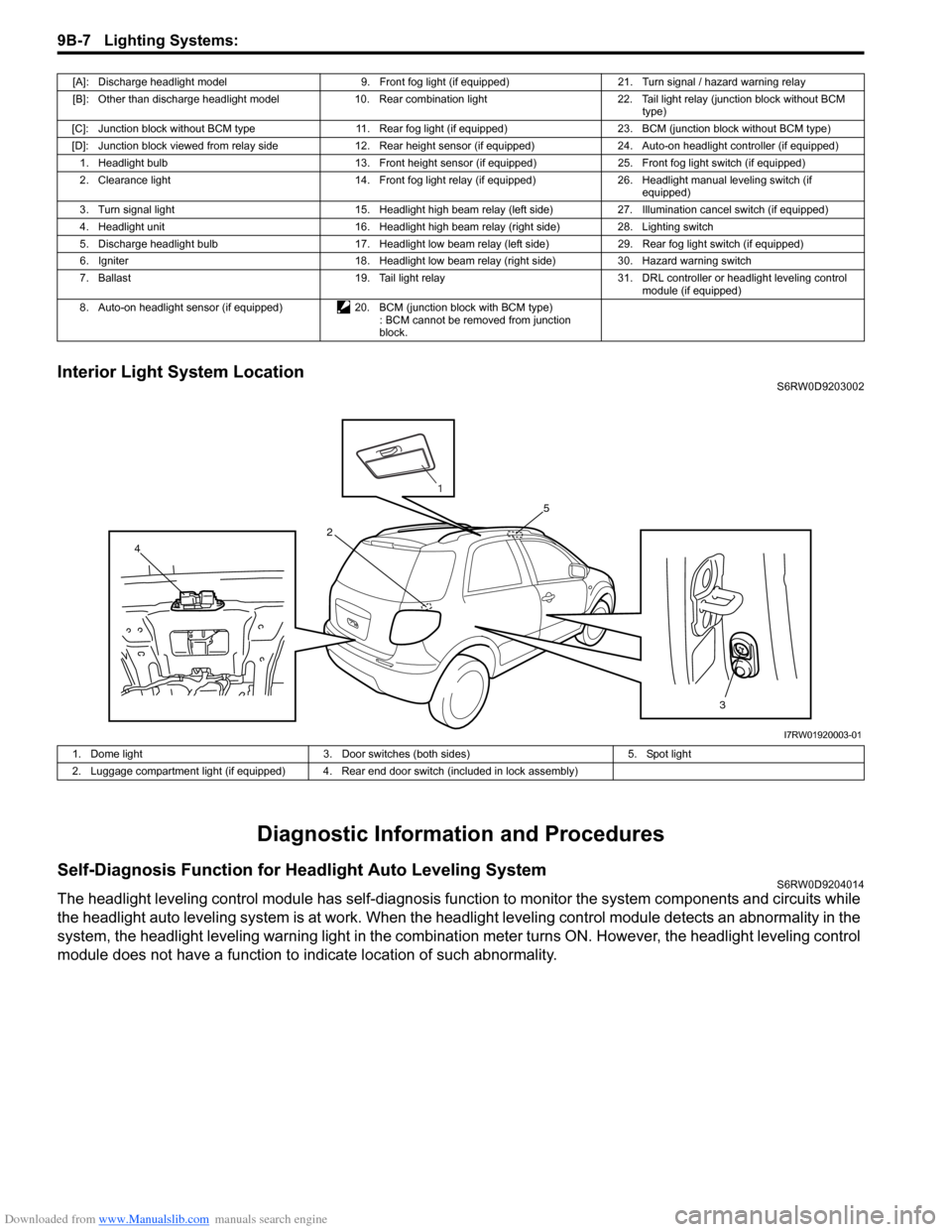
Interior Light System LocationS6RW0D9203002
Diagnostic Information and Procedures
Self-Diagnosis Function for Headlight Auto Leveling SystemS6RW0D9204014
The headlight leveling control module has self-diagnosis function to monitor the system components and circuits while
the headlight auto leveling system is at work. When the headlight leveling control module detects an abnormality in the
system, the headlight leveling warning light in the combination meter turns ON. However, the headlight leveling control
module does not have a function to indicate location of such abnormality.
[A]: Discharge headlight model 9. Front fog light (if equipped) 21. Turn signal / hazard warning relay
[B]: Other than discharge headlight model 10. Rear combination light 22. Tail light relay (junction block without BCM
type)
[C]: Junction block without BCM type 11. Rear fog light (if equipped) 23. BCM (junction block without BCM type)
[D]: Junction block viewed from relay side 12. Rear height sensor (if equipped) 24. Auto-on headlight controller (if equipped)
1. Headlight bulb 13. Front height sensor (if equipped) 25. Front fog light switch (if equipped)
2. Clearance light 14. Front fog light relay (if equipped) 26. Headlight manual leveling switch (if
equipped)
3. Turn signal light 15. Headlight high beam relay (left side) 27. Illumination cancel switch (if equipped)
4. Headlight unit 16. Headlight high beam relay (right side) 28. Lighting switch
5. Discharge headlight bulb 17. Headlight low beam relay (left side) 29. Rear fog light switch (if equipped)
6. Igniter 18. Headlight low beam relay (right side) 30. Hazard warning switch
7. Ballast 19. Tail light relay 31. DRL controller or headlight leveling control
module (if equipped)
8. Auto-on headlight sensor (if equipped) 20. BCM (junction block with BCM type)
: BCM cannot be removed from junction
block.
3 4
5
2
1
I7RW01920003-01
1. Dome light 3. Door switches (both sides) 5. Spot light
2. Luggage compartment light (if equipped) 4. Rear end door switch (included in lock assembly)
Page 1344 of 1556
Downloaded from www.Manualslib.com manuals search engine 9B-25 Lighting Systems:
Turn Signal and Hazard Warning Relay
Inspection
S6RW0D9206012
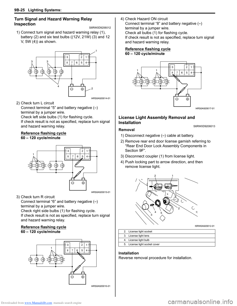
1) Connect turn signal and hazard warning relay (1),
battery (2) and six test bulbs ((12V, 21W) (3) and 12
V, 5W (4)) as shown.
2) Check turn L circuit
Connect terminal “5” and battery negative (–)
terminal by a jumper wire.
Check left side bulbs (1) for flashing cycle.
If check result is not as specified, replace turn signal
and hazard warning relay.
Reference flashing cycle
60 – 120 cycle/minute
3) Check turn R circuit
Connect terminal “6” and battery negative (–)
terminal by a jumper wire.
Check right side bulbs (1) for flashing cycle.
If check result is not as specified, replace turn signal
and hazard warning relay.
Reference flashing cycle
60 – 120 cycle/minute4) Check Hazard ON circuit
Connect terminal “8” and battery negative (–)
terminal by a jumper wire.
Check all bulbs (1) for flashing cycle.
If check result is not as specified, replace turn signal
and hazard warning relay.
Reference flashing cycle
60 – 120 cycle/minute
License Light Assembly Removal and
Installation
S6RW0D9206013
Removal
1) Disconnect negative (–) cable at battery.
2) Remove rear end door license garnish referring to
“Rear End Door Lock Assembly Components in
Section 9F”.
3) Disconnect coupler (1) from license light.
4) Push locking part to arrow direction, and then
remove license light.
Installation
Reverse removal procedure for installation.
2 4
33
3
87
12
654
1
I4RS0A920014-01
13
87
12
654
I4RS0A920015-01
3
87
12
6541
I4RS0A920016-01
2. License light socket
3. License light lens
4. License light bulb
5. License light socket cover
3
87
12
6
5411
I4RS0A920017-01
2
34
5
2 1
I5RW0A920012-01
Page 1371 of 1556
Downloaded from www.Manualslib.com manuals search engine Instrumentation / Driver Info. / Horn: 9C-19
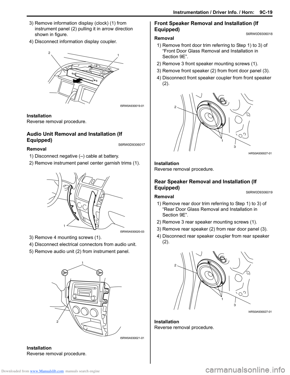
3) Remove information display (clock) (1) from
instrument panel (2) pulling it in arrow direction
shown in figure.
4) Disconnect information display coupler.
Installation
Reverse removal procedure.
Audio Unit Removal and Installation (If
Equipped)
S6RW0D9306017
Removal
1) Disconnect negative (–) cable at battery.
2) Remove instrument panel center garnish trims (1).
3) Remove 4 mounting screws (1).
4) Disconnect electrical connectors from audio unit.
5) Remove audio unit (2) from instrument panel.
Installation
Reverse removal procedure.
Front Speaker Removal and Installation (If
Equipped)
S6RW0D9306018
Removal
1) Remove front door trim referring to Step 1) to 3) of
“Front Door Glass Removal and Installation in
Section 9E”.
2) Remove 3 front speaker mounting screws (1).
3) Remove front speaker (2) from front door panel (3).
4) Disconnect front speaker coupler from front speaker
(2).
Installation
Reverse removal procedure.
Rear Speaker Removal and Installation (If
Equipped)
S6RW0D9306019
Removal
1) Remove rear door trim referring to Step 1) to 3) of
“Rear Door Glass Removal and Installation in
Section 9E”.
2) Remove 3 rear speaker mounting screws (1).
3) Remove rear speaker (2) from rear door panel (3).
4) Disconnect rear speaker coupler from rear speaker
(2).
Installation
Reverse removal procedure.
1 2
I5RW0A930019-01
1
I5RW0A930020-03
1
2
I5RW0A930021-01
1 2
3
I4RS0A930027-01
1 2
3
I4RS0A930027-01
Page 1380 of 1556
Downloaded from www.Manualslib.com manuals search engine 9D-6 Wipers / Washers:
Rear Wiper Removal and InstallationS6RW0D9406006
Removal
1) Disconnect negative (–) cable at battery.
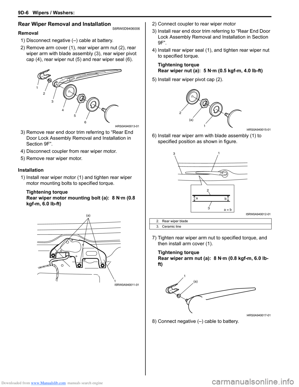
2) Remove arm cover (1), rear wiper arm nut (2), rear
wiper arm with blade assembly (3), rear wiper pivot
cap (4), rear wiper nut (5) and rear wiper seal (6).
3) Remove rear end door trim referring to “Rear End
Door Lock Assembly Removal and Installation in
Section 9F”.
4) Disconnect coupler from rear wiper motor.
5) Remove rear wiper motor.
Installation
1) Install rear wiper motor (1) and tighten rear wiper
motor mounting bolts to specified torque.
Tightening torque
Rear wiper motor mounting bolt (a): 8 N·m (0.8
kgf-m, 6.0 lb-ft)2) Connect coupler to rear wiper motor
3) Install rear end door trim referring to “Rear End Door
Lock Assembly Removal and Installation in Section
9F”.
4) Install rear wiper seal (1), and tighten rear wiper nut
to specified torque.
Tightening torque
Rear wiper nut (a): 5 N·m (0.5 kgf-m, 4.0 lb-ft)
5) Install rear wiper pivot cap (2).
6) Install rear wiper arm with blade assembly (1) to
specified position as shown in figure.
7) Tighten rear wiper arm nut to specified torque, and
then install arm cover (1).
Tightening torque
Rear wiper arm nut (a): 8 N·m (0.8 kgf-m, 6.0 lb-
ft)
8) Connect negative (–) cable to battery.
1
2
3
4
5
6
I4RS0A940013-01
1 (a)I5RW0A940011-01
2. Rear wiper blade
3. Ceramic line
2
1 (a)
I4RS0A940015-01
3 2a = b a
b
1
3
I5RW0A940012-01
1
(a)
I4RS0A940017-01
Page 1387 of 1556
Downloaded from www.Manualslib.com manuals search engine Glass / Windows / Mirrors: 9E-2
Schematic and Routing Diagram
Power Window Circuit Diagram (Pinching Prevention Function Model)S6RW0D9502001
6 5
[C][D]
DSB IG
E
SG SV SBSA DRU DRD
SG SV SBSA DRU DRDASU, RRU
or RLUASD, RRD
or RLD
[C][C]
D U
[C][D]
SU SBB [C][D] [E] [E]
ESG
SV SB SADRU DRD B ASU ASD
RRU
RRDDS IG RLD RLUSG SV SBSA DRU DRD [A] [B] 1
1
3
2
47
8
9
10
I6RW0D950001-01
[A]: Power window main switch connector
(viewed from harness side)1. Fuse 6. Pulse sensor 2
[B]: Driver side power window motor connector
(viewed from harness side)2. Driver side door switch 7. Window lock switch
[C]: UP 3. Power window main switch 8. Sub switch (passenger side, rear left side or rear light side)
[D]: DOWN 4. Driver side power window motor 9. Power window sub switch (passenger side, rear left side or
rear light side)
[E]: AUTO 5. Pulse sensor 1 10. Power window motor (other than driver side)
Page 1404 of 1556
Downloaded from www.Manualslib.com manuals search engine 9E-19 Glass / Windows / Mirrors:
Rear End Door Window Defogger Relay
Inspection
S6RW0D9506018
1) Disconnect negative (–) cable from battery.
2) Remove junction block for inspection of rear end
door window defogger relay.
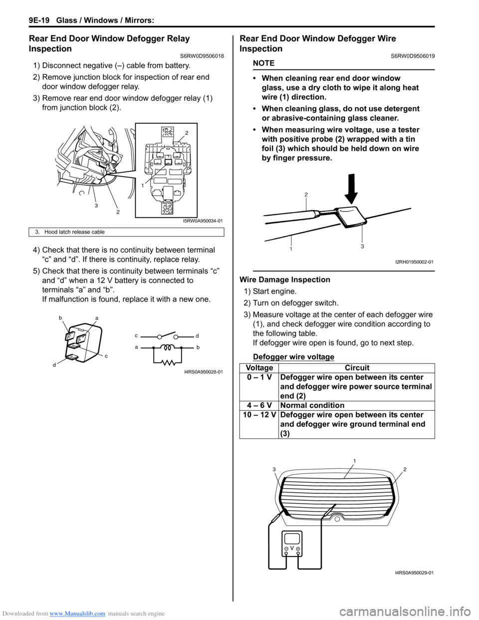
3) Remove rear end door window defogger relay (1)
from junction block (2).
4) Check that there is no continuity between terminal
“c” and “d”. If there is continuity, replace relay.
5) Check that there is continuity between terminals “c”
and “d” when a 12 V battery is connected to
terminals “a” and “b”.
If malfunction is found, replace it with a new one.
Rear End Door Window Defogger Wire
Inspection
S6RW0D9506019
NOTE
• When cleaning rear end door window
glass, use a dry cloth to wipe it along heat
wire (1) direction.
• When cleaning glass, do not use detergent
or abrasive-containing glass cleaner.
• When measuring wire voltage, use a tester
with positive probe (2) wrapped with a tin
foil (3) which should be held down on wire
by finger pressure.
Wire Damage Inspection
1) Start engine.
2) Turn on defogger switch.
3) Measure voltage at the center of each defogger wire
(1), and check defogger wire condition according to
the following table.
If defogger wire open is found, go to next step.
Defogger wire voltage
3. Hood latch release cable
12
2
3
I5RW0A950034-01
ba
c
dc
ad
bI4RS0A950028-01Voltage Circuit
0 – 1 V Defogger wire open between its center
and defogger wire power source terminal
end (2)
4 – 6 V Normal condition
10 – 12 V Defogger wire open between its center
and defogger wire ground terminal end
(3)
I2RH01950002-01
2
1
3
I4RS0A950029-01
Page 1412 of 1556
Downloaded from www.Manualslib.com manuals search engine 9F-1 Security and Locks:
Body, Cab and Accessories
Security and Locks
General Description
Key Coding ConstructionS6RW0D9601001
Key Usage and Identification
Key is used for ignition and door lock cylinders. Key is cut on both edges to make them reversible.
Key identification is obtained from five character key code stamped on key code tag. Using this key code, key code
cutting combination can be determined from a code list (available to owners of key cutting equipment from suppliers).
Rear End Door Opener System DescriptionS6RW0D9601002
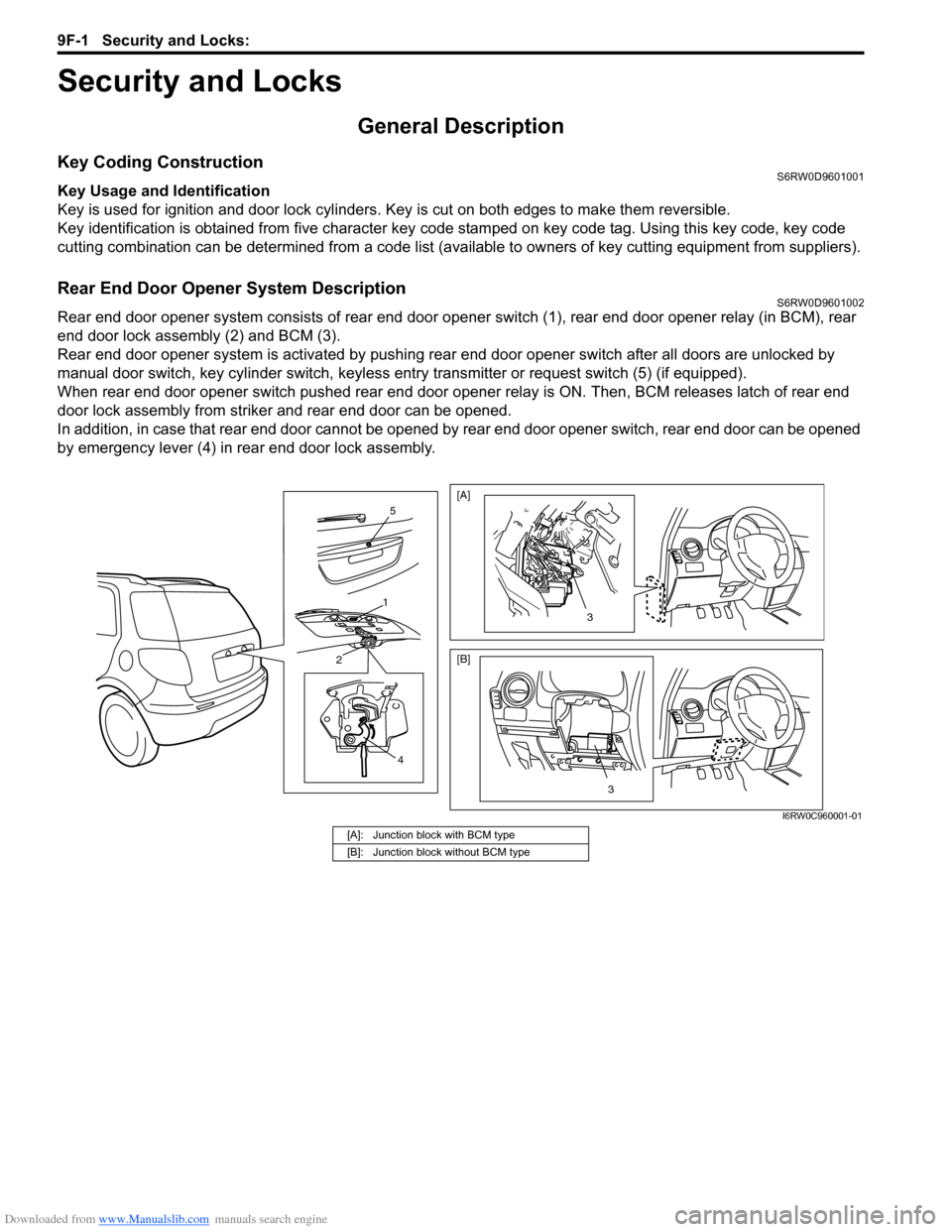
Rear end door opener system consists of rear end door opener switch (1), rear end door opener relay (in BCM), rear
end door lock assembly (2) and BCM (3).
Rear end door opener system is activated by pushing rear end door opener switch after all doors are unlocked by
manual door switch, key cylinder switch, keyless entry transmitter or request switch (5) (if equipped).
When rear end door opener switch pushed rear end door opener relay is ON. Then, BCM releases latch of rear end
door lock assembly from striker and rear end door can be opened.
In addition, in case that rear end door cannot be opened by rear end door opener switch, rear end door can be opened
by emergency lever (4) in rear end door lock assembly.
4
2
1
5
3
[A]
[B]
3
I6RW0C960001-01
[A]: Junction block with BCM type
[B]: Junction block without BCM type