2006 SUZUKI SX4 Glove box removal
[x] Cancel search: Glove box removalPage 933 of 1556

Downloaded from www.Manualslib.com manuals search engine Heater and Ventilation: 7A-5
• Check for operation and current.
a. Put blower motor (1) in a soft-jawed vise.
b. Connect battery to blower motor as shown.
c. Check if blower motor operates smoothly without
noise.
d. Check if ammeter indicates the specified current.
If measured current is out of specification, replace
blower motor.
Blower motor specified current at 12 V
18.5 A maximum at 20 – 25 °C (68 – 77 °F)
Blower Motor Resistor Removal and InstallationS6RW0D7106005
Removal
1) Disconnect negative (–) cable from battery.
2) Remove glove box from instrument panel.
3) Remove passenger side foot duct (1) from HVAC
unit by removing screw (2).4) Disconnect connector (1) from blower motor resistor
(2), and then remove blower motor resistor from
HVAC unit by removing screws (3).
Installation
Reverse removal procedure.
Blower Motor Resistor InspectionS6RW0D7106006
Measure each terminal-to-terminal resistance. If
measured resistance is out of specification, replace
blower motor resistor.
Blower motor resistor resistance
“H” – “MH”: Approx. 0.43 Ω at 20 – 25 °C (68 – 77 °F)
“MH” – “ML”: Approx. 0.6 Ω at 20 – 25 °C (68 – 77 °F)
“ML” – “L”: Approx. 2.0 Ω at 20 – 25 °C (68 – 77 °F)
1
I7RW01710006-01
1
2
I7RW01710007-01
2
3
1
I7RW01710008-01
I7RW01710009-02
Page 937 of 1556

Downloaded from www.Manualslib.com manuals search engine Heater and Ventilation: 7A-9
Blower Speed Selector InspectionS6RW0D7106010
Check blower speed selector for each terminal to
terminal continuity. If check result does not meet the
following conditions, replace HVAC control unit.
Air Intake Selector InspectionS6RW0D7106011
• Check that there is continuity between terminal (1)
and terminal (2) when air intake selector is at “FRE”
position.
• Check that there is no continuity between terminal (1)
and terminal (2) when air intake selector is at “REC”
position.
If check result does not meet the above conditions,
replace HVAC control unit.
Air Intake Control Actuator Removal and
Installation
S6RW0D7106012
Removal
1) Disconnect negative cable from battery.
2) Remove glove box from instrument panel.
3) Remove passenger side foot duct (1) from HVAC
unit by removing screw (2). (LH steering vehicle
only.)
4) Disconnect connector (1) from air intake control
actuator (2).
5) Detach linkage rod (3) and remove air intake control
actuator (2) by removing screws (4).
IHMH
GNDLML
PositionTerminalI
OFF
1
2
3
4LMLMHHGND
I4RS0A710019-01
1
2
I5RW0A710007-01
1
2
I7RW01710007-01
3
1
24I7RW01710016-02
Page 940 of 1556

Downloaded from www.Manualslib.com manuals search engine 7A-12 Heater and Ventilation:
Rear Duct Removal and Installation (If
Equipped)
S6RW0D7106016
Removal
1) Disconnect negative (–) cable at battery.
2) Remove front seats referring to “Front Seat Removal
and Installation in Section 9G”.
3) Remove console box referring to “Console Box
Components in Section 9H”.
4) Take off carpet till rear ducts is totally exposed.
5) Remove right and left rear ducts.
6) Remove center rear duct as follows, if necessary.
a) Remove HVAC control unit referring to “HVAC
Control Unit Removal and Installation” (non-A/C
or manual A/C) or “HVAC Control Module
Removal and Installation in Section 7B” (auto A/
C).
b) Remove center rear duct from HVAC unit.
Installation
Reverse removal procedure noting the following
instructions.
• Install HVAC control unit referring to “HVAC Control
Unit Removal and Installation” (non-A/C or manual A/
C) or “HVAC Control Module Removal and Installation
in Section 7B” (auto A/C), if removed.
• Install console box referring to “Console Box
Components in Section 9H”.
• Install front seats referring to “Front Seat Removal
and Installation in Section 9G”.
HVAC Air Filter Removal and Installation (If
Equipped)
S6RW0D7106017
Removal
1) Remove glove box from instrument panel.
2) Remove air filter (1) from HVAC unit while releasing
claws (2).
Installation
Reverse removal procedure noting the following
instructions.
• Position air filter by directing its arrow mark to the
upward.
HVAC Air Filter Inspection (If Equipped)S6RW0D7106018
Reference: “HVAC Air Filter Removal and Installation (If
Equipped)”
Check that filter is not excessively dirty, damage or oily,
clean filter with compressed air from air outlet side of
filter. If abnormality is found, replace filter with new one.
1. Center rear duct 4. Clip
2. Right rear duct 5. HVAC unit
3. Left rear duct
324 5
1
4
I7RW01710019-01
12
2
I6RW0C710010-01
I6RW0C710009-01
I4RS0A710032-01
Page 1136 of 1556

Downloaded from www.Manualslib.com manuals search engine 8B-97 Air Bag System:
Driver Air Bag (Inflator) Module InspectionS6RW0D8206006
WARNING!
Never disassemble air bag (inflator) module
or measure its resistance. Otherwise,
personal injury may result.
CAUTION!
If air bag (inflator) module was dropped from
a height of 90 cm (3 ft) or more, it should be
replaced.
Check air bag (inflator) module visually and if any of the
following is found, replace it with a new one.
• Air bag being deployed
• Trim cover (pad surface) (1) being cracked
• Inflator case (2) being damaged or having been
exposed to strong impact (dropped)
• Bend or deformity of air bag (inflator) module bracket.
Passenger Air Bag (Inflator) Module Removal
and Installation
S6RW0D8206007
WARNING!
• Never attempt to disassemble or repair the
passenger air bag (inflator) module. If any
abnormality is found, be sure to replace it
with new one as an assembly.
• Be sure to read “Precautions on Service
and Diagnosis of Air Bag System”,
“Precautions on Handling and Storage of
Air Bag System Components” and
“Precautions on Disposal of Air Bag and
Seat Belt Pretensioner” before starting to
work and observe every precaution during
work. Neglecting them may result in
personal injury or undeployment of the air
bag when necessary.
Removal
1) Disable air bag system. Refer to “Disabling Air Bag
System”.
2) Remove center ventilation louver with garnish
referring to “Center Ventilation Louver Removal and
Installation in Section 7A”.
3) Pull out glove box while pushing its stopper from
both right and left sides.
4) Remove passenger air bag (inflator) module
attaching bolts (1) and its facing cover bolt (6).
5) Hold up passenger air bag (inflator) module with its
facing cover (5) without extending wire harness (2)
to avoid air bag connector damage and to
disconnect passenger air bag (inflator) module
connector (3) as shown in figure.
a) Unlock lock button (4).
b) With lock button unlocked, disconnect connector.
6) Remove passenger air bag (inflator) module with its
facing cover (5) from instrument panel.
1
2
I5RW0A820067-01
“A”
5
“A”“A”
3
4a)
b)
2
6
1 1
I7RW01821033-01
Page 1137 of 1556

Downloaded from www.Manualslib.com manuals search engine Air Bag System: 8B-98
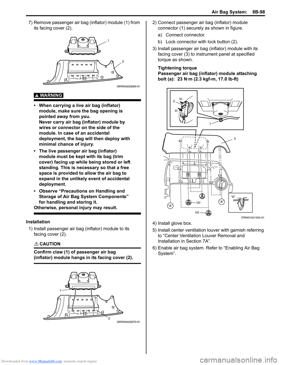
7) Remove passenger air bag (inflator) module (1) from
its facing cover (2).
WARNING!
• When carrying a live air bag (inflator)
module, make sure the bag opening is
pointed away from you.
Never carry air bag (inflator) module by
wires or connector on the side of the
module. In case of an accidental
deployment, the bag will then deploy with
minimal chance of injury.
• The live passenger air bag (inflator)
module must be kept with its bag (trim
cover) facing up while being stored or left
standing. This is necessary so that a free
space is provided to allow the air bag to
expand in the unlikely event of accidental
deployment.
• Observe “Precautions on Handling and
Storage of Air Bag System Components”
for handling and storing it.
Otherwise, personal injury may result.
Installation
1) Install passenger air bag (inflator) module to its
facing cover (2).
CAUTION!
Confirm claw (1) of passenger air bag
(inflator) module hangs in its facing cover (2).
2) Connect passenger air bag (inflator) module
connector (1) securely as shown in figure.
a) Connect connector.
b) Lock connector with lock button (2).
3) Install passenger air bag (inflator) module with its
facing cover (3) to instrument panel at specified
torque as shown.
Tightening torque
Passenger air bag (inflator) module attaching
bolt (a): 23 N·m (2.3 kgf-m, 17.0 lb-ft)
4) Install glove box.
5) Install center ventilation louver with garnish referring
to “Center Ventilation Louver Removal and
Installation in Section 7A”.
6) Enable air bag system. Refer to “Enabling Air Bag
System”.
1
2
I5RW0A820069-01
1
2
I5RW0A820070-01
“A”
3
“A”“A”
2
a)b)
1
(a)
(a)
I7RW01821034-01
Page 1145 of 1556

Downloaded from www.Manualslib.com manuals search engine Air Bag System: 8B-106
Passenger Air Bag (Inflator) Module Repair
Harness Installation
S6RW0D8206017
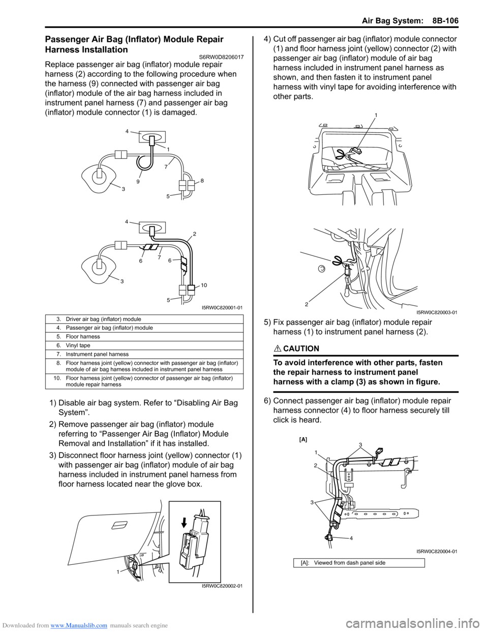
Replace passenger air bag (inflator) module repair
harness (2) according to the following procedure when
the harness (9) connected with passenger air bag
(inflator) module of the air bag harness included in
instrument panel harness (7) and passenger air bag
(inflator) module connector (1) is damaged.
1) Disable air bag system. Refer to “Disabling Air Bag
System”.
2) Remove passenger air bag (inflator) module
referring to “Passenger Air Bag (Inflator) Module
Removal and Installation” if it has installed.
3) Disconnect floor harness joint (yellow) connector (1)
with passenger air bag (inflator) module of air bag
harness included in instrument panel harness from
floor harness located near the glove box.4) Cut off passenger air bag (inflator) module connector
(1) and floor harness joint (yellow) connector (2) with
passenger air bag (inflator) module of air bag
harness included in instrument panel harness as
shown, and then fasten it to instrument panel
harness with vinyl tape for avoiding interference with
other parts.
5) Fix passenger air bag (inflator) module repair
harness (1) to instrument panel harness (2).
CAUTION!
To avoid interference with other parts, fasten
the repair harness to instrument panel
harness with a clamp (3) as shown in figure.
6) Connect passenger air bag (inflator) module repair
harness connector (4) to floor harness securely till
click is heard.
3. Driver air bag (inflator) module
4. Passenger air bag (inflator) module
5. Floor harness
6. Vinyl tape
7. Instrument panel harness
8. Floor harness joint (yellow) connector with passenger air bag (inflator)
module of air bag harness included in instrument panel harness
10. Floor harness joint (yellow) connector of passenger air bag (inflator)
module repair harness
5
2
4
4
7
7
1
3
3
5
66
8
10
9
I5RW0C820001-01
1
I5RW0C820002-01
[A]: Viewed from dash panel side
1
2
I5RW0C820003-01
3
4 213
[A]
I5RW0C820004-01
Page 1349 of 1556

Downloaded from www.Manualslib.com manuals search engine Lighting Systems: 9B-30
Height Sensor and Its Circuit Inspection (If
Equipped)
S6RW0D9206028
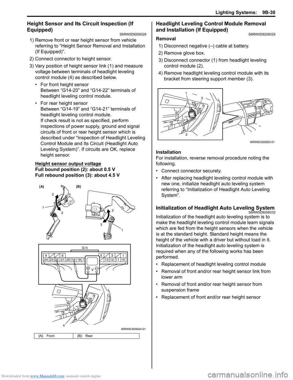
1) Remove front or rear height sensor from vehicle
referring to “Height Sensor Removal and Installation
(If Equipped)”.
2) Connect connector to height sensor.
3) Vary position of height sensor link (1) and measure
voltage between terminals of headlight leveling
control module (4) as described below.
• For front height sensor
Between “G14-20” and “G14-22” terminals of
headlight leveling control module.
• For rear height sensor
Between “G14-19” and “G14-21” terminals of
headlight leveling control module.
If check result is not as specified, perform
inspections of power supply, ground and signal
circuits of front or rear height sensor which is
described under “Inspection of Headlight Leveling
Control Module and Its Circuit (Headlight Auto
Leveling System)”. If circuits are OK, replace
height sensor.
Height sensor output voltage
Full bound position (2): about 0.5 V
Full rebound position (3): about 4.5 V
Headlight Leveling Control Module Removal
and Installation (If Equipped)
S6RW0D9206029
Removal
1) Disconnect negative (–) cable at battery.
2) Remove glove box.
3) Disconnect connector (1) from headlight leveling
control module (2).
4) Remove headlight leveling control module with its
bracket from steering support member (3).
Installation
For installation, reverse removal procedure noting the
following.
• Connect connector securely.
• After replacing headlight leveling control module with
new one, initialize headlight auto leveling system
referring to “Initialization of Headlight Auto Leveling
System”.
Initialization of Headlight Auto Leveling SystemS6RW0D9206030
Initialization of the headlight auto leveling system is to
make the headlight leveling control module learn signals
which are fed from the height sensors when the vehicle
is at the standard height. Standard height means the
height of the vehicle with a driver but without load in it.
Initialization of the headlight auto leveling system is
required when any of the following works has been
performed.
• Replacement of headlight leveling control module
• Removal of front and/or rear height sensor link from
lower arm
• Removal of front and/or rear height sensor from
suspension frame
• Replacement of front and/or rear height sensor
[A]: Front [B]: Rear
[A] [B]
4
G14
10 11 12 13 16 17 18 19 2031 5 6 9
21 22 23 24
V
2
3 1
2
3
1
I6RW0C920024-01
23 1
I6RW0C920025-01
Page 1369 of 1556

Downloaded from www.Manualslib.com manuals search engine Instrumentation / Driver Info. / Horn: 9C-17
Outside Air Temperature Sensor Removal and
Installation (If Equipped)
S6RW0D9306013
Removal
1) Disconnect negative (–) cable at battery.
2) Remove front bumper referring to “Front Bumper
and Rear Bumper Components in Section 9K”.
3) Disconnect connector from outside air temperature
sensor.
4) Remove outside air temperature sensor (1) from
front bumper member.
Installation
Reverse removal procedure for installation.
Outside Air Temperature Sensor Inspection (If
Equipped)
S6RW0D9306014
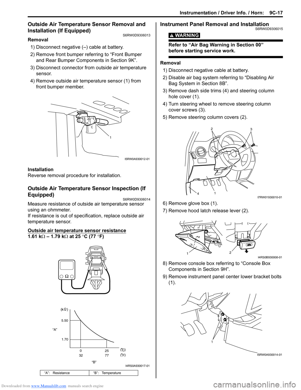
Measure resistance of outside air temperature sensor
using an ohmmeter.
If resistance is out of specification, replace outside air
temperature sensor.
Outside air temperature sensor resistance
1.61 kΩ – 1.79 kΩ at 25 °C (77 °F)
Instrument Panel Removal and InstallationS6RW0D9306015
WARNING!
Refer to “Air Bag Warning in Section 00”
before starting service work.
Removal
1) Disconnect negative cable at battery.
2) Disable air bag system referring to “Disabling Air
Bag System in Section 8B”.
3) Remove dash side trims (4) and steering column
hole cover (1).
4) Turn steering wheel to remove steering column
cover screws (3).
5) Remove steering column covers (2).
6) Remove glove box (1).
7) Remove hood latch release lever (2).
8) Remove console box referring to “Console Box
Components in Section 9H”.
9) Remove instrument panel center lower bracket bolts
(1).
“A”: Resistance “B”: Temperature
1
I5RW0A930012-01
“B” “A”5.50
1.70
0
3225
77
F
I4RS0A930017-01
2
3
1
4I7RW01930010-01
2
1I4RS0B930008-01
1
I5RW0A930014-01