2006 SUZUKI SX4 sensor
[x] Cancel search: sensorPage 468 of 1556

Downloaded from www.Manualslib.com manuals search engine 2C-9 Rear Suspension:
Installation
1) Insert wheel stud bolt (1) in hub hole. Rotate wheel
stud bolt slowly to assure that serrations are aligned
with those made by original bolt.
2) Install brake back plate, rear wheel hub and new rear
wheel hub bolts and then tighten rear wheel hub
mounting bolts to specified torque.
CAUTION!
Use new rear wheel hub mounting bolts.
Tightening torque
Rear wheel hub mounting bolt: 73 N·m (7.3 kgf-
m, 53.0 lb-ft)
3) For 4WD model, install rear drive shaft referring to
“Rear Drive Shaft Assembly Removal and
Installation in Section 3A”.
CAUTION!
Never reuse rear drive shaft nut.
Tightening torque
Drive shaft nut (a): 175 N·m (17.5 kgf-m, 127.0
lb-ft)4) Connect wheel speed sensor and tighten wheel
speed sensor bolt (2WD model) to specified torque.
Tightening torque
Wheel speed sensor bolt : 11 N·m (1.1 kgf-m, 8.0
lb-ft)
5) Connect brake pipe (1) to wheel cylinder and tighten
brake pipe flare nut to specified torque.
Tightening torque
Brake pipe flare nut (a): 16 N·m (1.6 kgf-m, 11.5
lb-ft)
6) Install brake drum referring to Step 1) and 2) of
“Installation” under “Rear Brake Drum Removal and
Installation in Section 4C”.
7) Fill reservoir with brake fluid and bleed brake
system. For bleeding operation, see “Air Bleeding of
Brake System in Section 4A”.
8) Install wheel and tighten wheel nuts to specified
torque.
Tightening torque
Wheel nut: 85 N·m (8.5 kgf-m, 61.5 lb-ft)
9) Upon completion of all jobs, depress brake pedal
with about 300 N (30 kg, 66 lbs) load at least 3 times
so as to obtain proper drum-to-shoe clearance.
Adjust parking brake cable. For adjustment, see
“Parking Brake Inspection and Adjustment in Section
4D”.
10) Check to ensure that brake drum is free from
dragging and proper braking is obtained.
11) Perform brake test (foot brake and parking brake).
12) Check each installed part for fluid leakage.
1
I5JB0A220017-01
1,(a)
1
I7RW01230012-01
(a)
1
I5RW0A230018-01
Page 469 of 1556

Downloaded from www.Manualslib.com manuals search engine Rear Suspension: 2C-10
Specifications
Tightening Torque SpecificationsS6RW0D2307001
NOTE
The specified tightening torque is also described in the following.
“Rear Suspension Components”
Reference:
For the tightening torque of fastener not specified in this section, refer to “Fasteners Information in Section 0A”. Fastening partTightening torque
Note
N⋅mkgf-mlb-ft
Wheel nut 85 8.5 61.5�) / �) / �) / �) / �)
Rear shock absorber upper nut 30 3.0 22.0�)
Rear shock absorber lower nut 90 9.0 65.0�) / �) / �)
Rear axle bolt 73 7.3 53.0�) / �)
Brake pipe flare nut 16 1.6 11.5�) / �)
Rear wheel hub mounting bolt 73 7.3 53.0�)
Drive shaft nut 175 17.5 127.0�)
Wheel speed sensor bolt 11 1.1 8.0�)
Page 477 of 1556

Downloaded from www.Manualslib.com manuals search engine Table of Contents 3- i
3
Section 3
CONTENTS
Driveline / Axle
Precautions ................................................. 3-1
Precautions............................................................. 3-1
Precautions on Driveline / Axle ............................. 3-1
Drive Shaft / Axle ..................................... 3A-1
Front ......................................................................... 3A-1
General Description ............................................. 3A-1
Front Drive Shaft Construction ............................ 3A-1
Component Location ........................................... 3A-1
Front Drive Shaft Assembly Components
Location ............................................................ 3A-1
Diagnostic Information and Procedures ............ 3A-2
Front Drive Shaft Symptom Diagnosis ................ 3A-2
Repair Instructions .............................................. 3A-2
Front Drive Shaft Components ........................... 3A-2
Front Drive Shaft Assembly On-Vehicle
Inspection.......................................................... 3A-3
Front Drive Shaft Assembly Removal and
Installation ......................................................... 3A-3
Front Drive Shaft Disassembly and
Reassembly ...................................................... 3A-4
Center Shaft and Center Bearing Support
Disassembly and Reassembly (If Equipped) .. 3A-12
Specifications..................................................... 3A-13
Tightening Torque Specifications ...................... 3A-13
Special Tools and Equipment ........................... 3A-14
Recommended Service Material ....................... 3A-14
Special Tool ...................................................... 3A-14
Rear ........................................................................ 3A-15
General Description ........................................... 3A-15
Rear Drive Shaft Construction .......................... 3A-15
Repair Instructions ............................................ 3A-15
Rear Drive Shaft Components .......................... 3A-15
Rear Drive Shaft Assembly Removal and
Installation ....................................................... 3A-16
Rear Drive Shaft Disassembly and
Reassembly .................................................... 3A-16
Specifications..................................................... 3A-18
Tightening Torque Specifications ...................... 3A-18
Special Tools and Equipment ........................... 3A-18
Recommended Service Material ....................... 3A-18
Special Tool ...................................................... 3A-18
Differential ................................................ 3B-1
Precautions...........................................................3B-1
Precaution for Rear Differential Oil Leakage....... 3B-1
Precautions in Diagnosing Trouble ..................... 3B-1
General Description .............................................3B-2
Rear Differential Description ............................... 3B-2
Coupling Description ........................................... 3B-2
4WD Control System Components ..................... 3B-3
4WD Control System Description........................ 3B-4
Function of 4WD Control System Component .... 3B-4
4WD Control System Wiring Circuit Diagram...... 3B-5
Terminal Arrangement of 4WD Control
Module .............................................................. 3B-5
Input / Output Signal Table of 4WD Control
Module .............................................................. 3B-6
On-Board Diagnostic System Description ........... 3B-6
CAN Communication System Description........... 3B-7
Diagnostic Information and Procedures ............3B-8
4WD Control System Check ............................... 3B-8
4WD Position Indicator Operation Check.......... 3B-10
4WD Control System Operation Inspection ...... 3B-10
Visual Inspection ............................................... 3B-11
DTC Check........................................................ 3B-11
DTC Clearance ................................................. 3B-11
DTC Table ......................................................... 3B-12
Fail-Safe Table .................................................. 3B-12
Scan Tool Data ................................................. 3B-13
Rear Differential Symptom Diagnosis ............... 3B-14
4WD Control Symptom Diagnosis..................... 3B-14
4WD Position Indicator Does Not Come ON at
Ignition Switch ON but Engine Stops .............. 3B-15
4WD Position Indicator Remains ON Steady
at Ignition Switch ON....................................... 3B-16
DTC C1240: 4WD Control Module Power
Supply Circuit Malfunction............................... 3B-17
DTC C1243: Internal Circuit Malfunction of
4WD Control Module ....................................... 3B-18
DTC C1250: Coupling Air Temperature
Sensor Circuit Open ........................................ 3B-19
DTC C1251: Coupling Air Temperature
Sensor Circuit Short ........................................ 3B-21
DTC C1252: Coupling Assembly Circuit Open .. 3B-22
DTC C1253: Coupling Assembly Circuit Short .. 3B-24
DTC C1254: 2WD/4WD Switch Malfunction ..... 3B-25
DTC U0073: Control Module Communication
Bus Off ............................................................ 3B-27
Page 478 of 1556

Downloaded from www.Manualslib.com manuals search engine 3-ii Table of Contents
DTC U0100: Lost Communication with ECM .... 3B-27
DTC U0121: Lost Communication with ABS /
ESP® Control Module..................................... 3B-27
DTC U0155: Lost Communication with
Instrument Panel Cluster (IPC) Control
Module ............................................................ 3B-27
Inspection of 4WD Control Module and Its
Circuits ............................................................ 3B-27
Repair Instructions ............................................3B-30
Rear Differential Oil Level Check ...................... 3B-30
Rear Differential Oil Change ............................. 3B-30
2WD/4WD Switch Removal and Installation ..... 3B-31
2WD/4WD Switch Inspection ............................ 3B-31
4WD Control Module Removal and
Installation ....................................................... 3B-31
Coupling Air Temperature Sensor Removal
and Installation ................................................ 3B-31
Coupling Air Temperature Sensor Inspection ... 3B-32
Coupling Assembly Inspection .......................... 3B-32
Rear Differential Mountings Components ......... 3B-33
Front Mounting Arm and/or Rear Mounting
Bracket Assembly Removal and Installation ... 3B-34
Rear Mounting Bracket Assembly
Disassembly and Reassembly ........................ 3B-34
Rear Differential Dismounting and
Remounting ..................................................... 3B-34
Rear Differential Components ........................... 3B-35
Rear Differential Disassembly and
Reassembly .................................................... 3B-36
Rear Differential Inspection ............................... 3B-47
Specifications .....................................................3B-48
Tightening Torque Specifications ...................... 3B-48
Special Tools and Equipment ...........................3B-48
Recommended Service Material ....................... 3B-48
Special Tool ...................................................... 3B-49
Transfer .................................................... 3C-1
General Description ............................................. 3C-1
Transfer Description ............................................ 3C-1Diagnostic Information and Procedures ............3C-1
Transfer Symptom Diagnosis..............................3C-1
Repair Instructions ..............................................3C-2
Transfer Oil Level Check.....................................3C-2
Transfer Oil Change ............................................3C-2
Transfer Dismounting and Remounting ..............3C-3
Transfer Assembly Components .........................3C-4
Transfer Assembly Disassembly and
Reassembly ......................................................3C-5
Reduction Drive Gear Assembly Disassembly
and Reassembly ...............................................3C-7
Reduction Driven Gear Assembly
Disassembly and Reassembly ..........................3C-8
Transfer Right Case and Left Case
Disassembly and Reassembly ..........................3C-9
Transfer Output Retainer Assembly
Disassembly and Reassembly ........................3C-10
Transfer Assembly Inspection ...........................3C-14
Bevel Gear Tooth Contact Inspection ...............3C-14
Specifications .....................................................3C-16
Tightening Torque Specifications ......................3C-16
Special Tools and Equipment ...........................3C-17
Recommended Service Material .......................3C-17
Special Tool ......................................................3C-17
Propeller Shafts ....................................... 3D-1
Precautions ...........................................................3D-1
Propeller Shaft Caution .......................................3D-1
General Description .............................................3D-1
Propeller Shaft Construction ...............................3D-1
Diagnostic Information and Procedures ............3D-1
Propeller Shaft Symptom Diagnosis ...................3D-1
Repair Instructions ..............................................3D-2
Propeller Shaft Joint Check.................................3D-2
Propeller Shaft Assembly Removal and
Installation .........................................................3D-2
Propeller Shaft Inspection ...................................3D-2
Specifications .......................................................3D-3
Tightening Torque Specifications ........................3D-3
Page 482 of 1556

Downloaded from www.Manualslib.com manuals search engine 3A-3 Drive Shaft / Axle: Front
Front Drive Shaft Assembly On-Vehicle
Inspection
S6RW0D3116002
• Check boots for breakage or deterioration.
• Check wheel side joint for rattle or smooth rotation.
• Check differential side (or center shaft side) joint for
smooth rotation.
If any abnormality is found, replace.
Front Drive Shaft Assembly Removal and
Installation
S6RW0D3116003
Removal
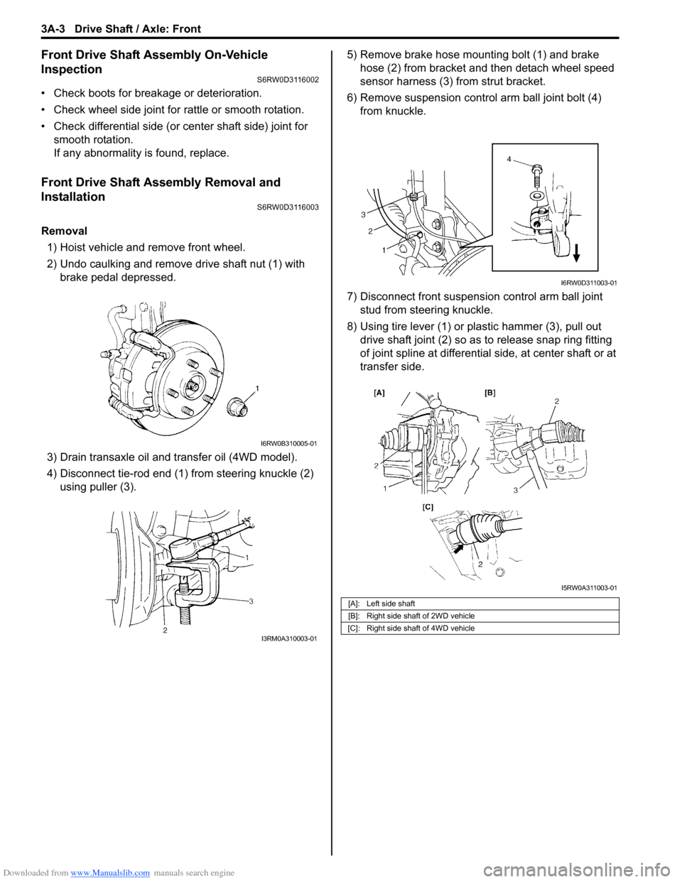
1) Hoist vehicle and remove front wheel.
2) Undo caulking and remove drive shaft nut (1) with
brake pedal depressed.
3) Drain transaxle oil and transfer oil (4WD model).
4) Disconnect tie-rod end (1) from steering knuckle (2)
using puller (3).5) Remove brake hose mounting bolt (1) and brake
hose (2) from bracket and then detach wheel speed
sensor harness (3) from strut bracket.
6) Remove suspension control arm ball joint bolt (4)
from knuckle.
7) Disconnect front suspension control arm ball joint
stud from steering knuckle.
8) Using tire lever (1) or plastic hammer (3), pull out
drive shaft joint (2) so as to release snap ring fitting
of joint spline at differential side, at center shaft or at
transfer side.
I6RW0B310005-01
I3RM0A310003-01
[A]: Left side shaft
[B]: Right side shaft of 2WD vehicle
[C]: Right side shaft of 4WD vehicle
I6RW0D311003-01
I5RW0A311003-01
Page 499 of 1556

Downloaded from www.Manualslib.com manuals search engine Differential: 3B-2
General Description
Rear Differential DescriptionS6RW0D3201001
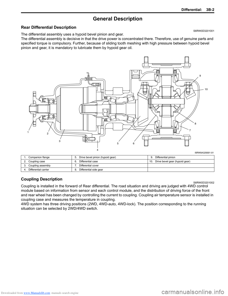
The differential assembly uses a hypoid bevel pinion and gear.
The differential assembly is decisive in that the drive power is concentrated there. Therefore, use of genuine parts and
specified torque is compulsory. Further, because of sliding tooth meshing with high pressure between hypoid bevel
pinion and gear, it is mandatory to lubricate them by hypoid gear oil.
Coupling DescriptionS6RW0D3201002
Coupling is installed in the forward of Rear differential. The road situation and driving are judged with 4WD control
module based on information from sensor and each control module, and the distribution of driving force of the front
and rear wheel has been changed by controlling the current to coupling. Coupling air temperature sensor is installed in
coupling case and measures the temperature in coupling.
4WD system has three driving positions (2WD, 4WD-auto, 4WD-lock). The position corresponding to the running
situation can be selected by 2WD/4WD switch.
1
2
3
4567810 9
I5RW0A320001-01
1. Companion flange 5. Drive bevel pinion (hypoid gear) 9. Differential pinion
2. Coupling case 6. Differential case 10. Drive bevel gear (hypoid gear)
3. Coupling assembly 7. Differential cover
4. Differential carrier 8. Differential side gear
Page 500 of 1556

Downloaded from www.Manualslib.com manuals search engine 3B-3 Differential:
4WD Control System ComponentsS6RW0D3201003
2
1
3
6
5 4
I5RW0A320002-04
1. 4WD control module 3. 4WD LOCK indicator 5. Coupling assembly
2. 4WD AUTO indicator 4. 2WD/4WD switch 6. Coupling air temperature sensor
Page 502 of 1556

Downloaded from www.Manualslib.com manuals search engine 3B-5 Differential:
4WD Control System Wiring Circuit DiagramS6RW0D3201006
Terminal Arrangement of 4WD Control ModuleS6RW0D3201007
5V
5V
12V
G26-3
YEL
GRY
G26-2
G26-22G26-23REDWHT
G26-13
G26-14
G26-12
G26-11
G26-10BLK
WHT/RED
RED/BLK
GRY/YEL
RED/WHT
12V
L102-1
L102-4
1
37
9
10
12
13
14
12V
G26-21BLU
G26-25
G26-24ORN
BRN
5V
28
11
WHT
WHT
WHTWHTWHTWHT
WHT
RED
RED
RED
REDRED
RED
RED
46
5
L174-4BLK/ORNL174-5L174-1
I7RW01320001-01
1. Coupling assembly 6. ECM 11. Data link connector (DLC)
2. Coupling air temperature sensor 7. 4WD control module 12. “IG COIL” fuse
3. Combination meter 8. 2WD/4WD switch 13. “4WD” fuse
4. BCM 9. “4WD” switch 14. Main fuse box
5. ABS / ESP® control module 10. “4WD lock” switch
1 2 3 4 5 6 7 8 9 10 11 12
13 14 15 16 17 18 19 20 21 22 23 24 25 26
[A]
I4JA01332038-01
[A]: Connector “G26” viewed from harness side
Te r m i n a l C i r c u i t Te r m i n a l C i r c u i t
G26-2 Coupling assembly (power) G26-14 “4WD lock” switch
G26-3 Coupling assembly (ground) G26-21 Data link connector (DLC)
G26-10 Ground G26-22 CAN communication line (high)
G26-11 Power source for internal memory G26-23 CAN communication line (low)
G26-12 Power source G26-24 Coupling air temperature sensor (ground)
G26-13 “4WD” switch G26-25 Coupling air temperature sensor (power)