2006 SUZUKI SX4 Precautions
[x] Cancel search: PrecautionsPage 1338 of 1556
Downloaded from www.Manualslib.com manuals search engine 9B-19 Lighting Systems:
Headlight Bulb Replacement (Discharge
Headlight Model)
S6RW0D9206002
WARNING!
• To avoid danger of being burned, don’t
touch when the bulb is hot.
• Don’t touch glass surface of bulb, to avoid
deteriorate as the case may be unclear
when bulb light on at dirty condition.
• Be sure to read “Precautions for Discharge
Headlight Service (If Equipped)” before
starting to service work.
1) Check to ensure that lighting switch is at OFF
position.
2) Disconnect negative (–) cable at battery.
3) Remove headlight housing referring to “Headlight
Housing Removal and Installation”.
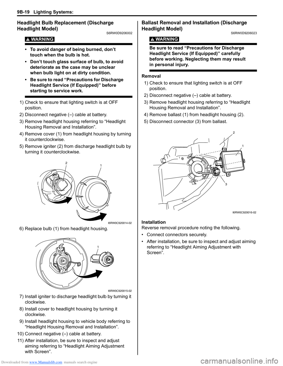
4) Remove cover (1) from headlight housing by turning
it counterclockwise.
5) Remove igniter (2) from discharge headlight bulb by
turning it counterclockwise.
6) Replace bulb (1) from headlight housing.
7) Install igniter to discharge headlight bulb by turning it
clockwise.
8) Install cover to headlight housing by turning it
clockwise.
9) Install headlight housing to vehicle body referring to
“Headlight Housing Removal and Installation”.
10) Connect negative (–) cable at battery.
11) After installation, be sure to inspect and adjust
aiming referring to “Headlight Aiming Adjustment
with Screen”.
Ballast Removal and Installation (Discharge
Headlight Model)
S6RW0D9206023
WARNING!
Be sure to read “Precautions for Discharge
Headlight Service (If Equipped)” carefully
before working. Neglecting them may result
in personal injury.
Removal
1) Check to ensure that lighting switch is at OFF
position.
2) Disconnect negative (–) cable at battery.
3) Remove headlight housing referring to “Headlight
Housing Removal and Installation”.
4) Remove ballast (1) from headlight housing (2).
5) Disconnect connector (3) from ballast.
Installation
Reverse removal procedure noting the following.
• Connect connectors securely.
• After installation, be sure to inspect and adjust aiming
referring to “Headlight Aiming Adjustment with
Screen”.
1 2
I6RW0C920014-02
1
I6RW0C920015-02
2
1
3
I6RW0C920016-02
Page 1339 of 1556
Downloaded from www.Manualslib.com manuals search engine Lighting Systems: 9B-20
Igniter Removal and Installation (Discharge
Headlight Model)
S6RW0D9206024
WARNING!
Be sure to read “Precautions for Discharge
Headlight Service (If Equipped)” carefully
before working. Neglecting them may result
in personal injury.
Removal
1) Remove ballast referring to “Ballast Removal and
Installation (Discharge Headlight Model)”.
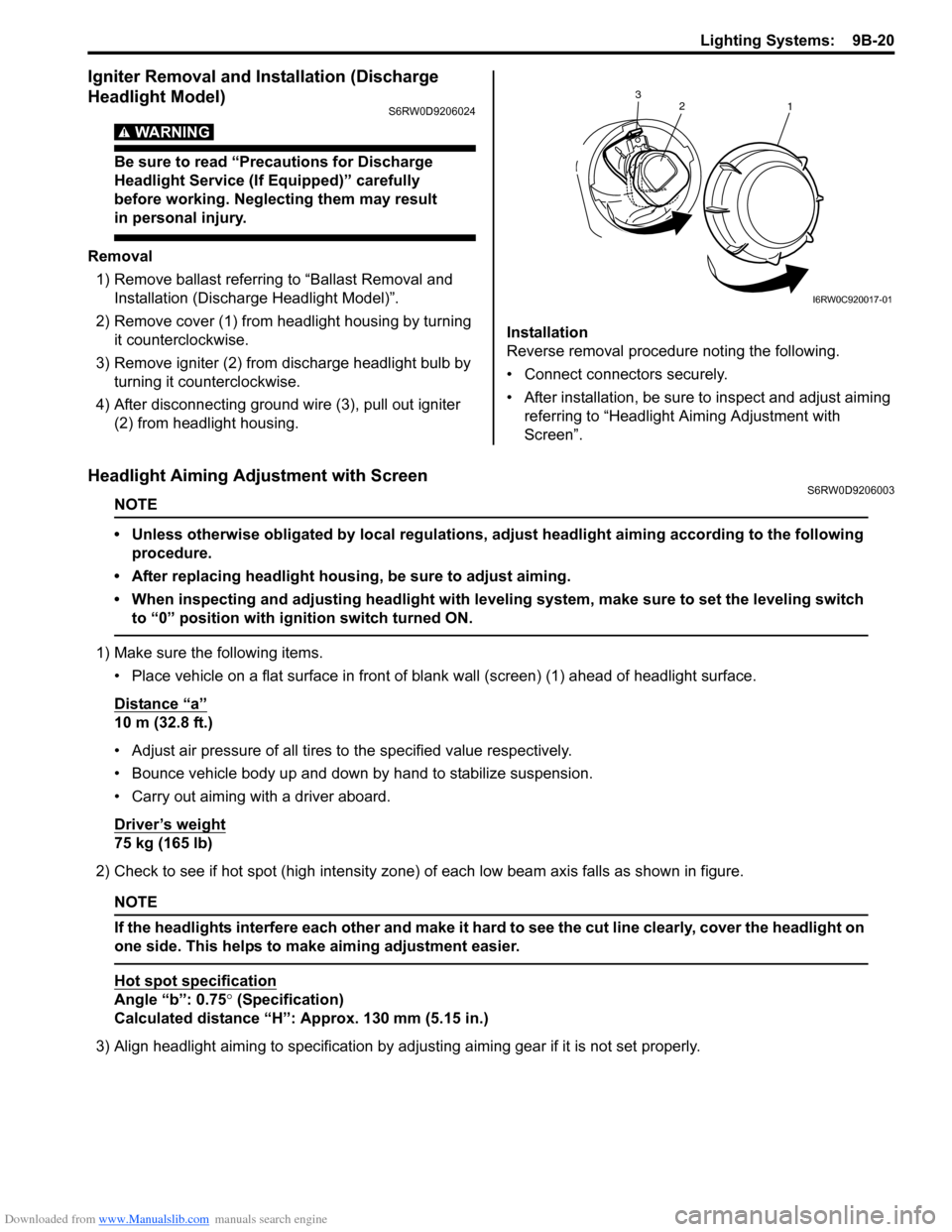
2) Remove cover (1) from headlight housing by turning
it counterclockwise.
3) Remove igniter (2) from discharge headlight bulb by
turning it counterclockwise.
4) After disconnecting ground wire (3), pull out igniter
(2) from headlight housing.Installation
Reverse removal procedure noting the following.
• Connect connectors securely.
• After installation, be sure to inspect and adjust aiming
referring to “Headlight Aiming Adjustment with
Screen”.
Headlight Aiming Adjustment with ScreenS6RW0D9206003
NOTE
• Unless otherwise obligated by local regulations, adjust headlight aiming according to the following
procedure.
• After replacing headlight housing, be sure to adjust aiming.
• When inspecting and adjusting headlight with leveling system, make sure to set the leveling switch
to “0” position with ignition switch turned ON.
1) Make sure the following items.
• Place vehicle on a flat surface in front of blank wall (screen) (1) ahead of headlight surface.
Distance “a”
10 m (32.8 ft.)
• Adjust air pressure of all tires to the specified value respectively.
• Bounce vehicle body up and down by hand to stabilize suspension.
• Carry out aiming with a driver aboard.
Driver’s weight
75 kg (165 lb)
2) Check to see if hot spot (high intensity zone) of each low beam axis falls as shown in figure.
NOTE
If the headlights interfere each other and make it hard to see the cut line clearly, cover the headlight on
one side. This helps to make aiming adjustment easier.
Hot spot specification
Angle “b”: 0.75° (Specification)
Calculated distance “H”: Approx. 130 mm (5.15 in.)
3) Align headlight aiming to specification by adjusting aiming gear if it is not set properly.
2
1 3
I6RW0C920017-01
Page 1353 of 1556
Downloaded from www.Manualslib.com manuals search engine Instrumentation / Driver Info. / Horn: 9C-1
Body, Cab and Accessories
Instrumentation / Driver Info. / Horn
Precautions
Precautions in Diagnosing Troubles for Combination MeterS6RW0D9300001
Combination meter uses signals (information) from each control module by CAN communication to control
speedometer, tachometer, fuel meter, engine coolant temp meter, warning light and indicator light (other than air bag
warning light, EPS warning light, headlight leveling warning light (if equipped), rear fog light indicator light (if
equipped), high beam indicator light and turn signal indicator light). Therefor, check that no DTC is detected in each
module before performing combination meter symptom diagnosis. If any DTC is detected, correct trouble indicated by
that DTC troubleshooting first.
General Description
CAN Communication System DescriptionS6RW0D9301001
Refer to “CAN Communication System Description in Section 1A” for CAN communication system description.
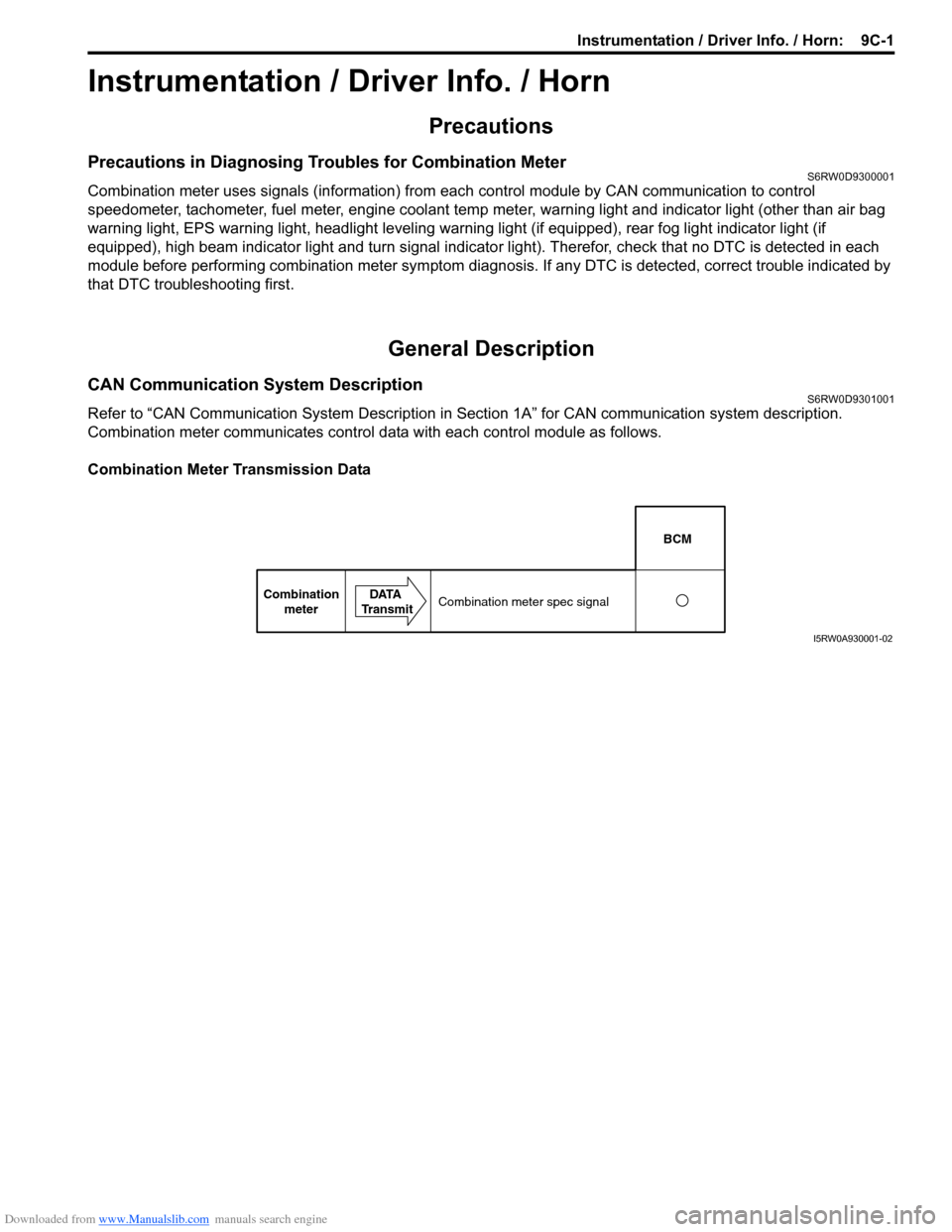
Combination meter communicates control data with each control module as follows.
Combination Meter Transmission Data
BCM
Combination
meterDATA
TransmitCombination meter spec signal
I5RW0A930001-02
Page 1386 of 1556
Downloaded from www.Manualslib.com manuals search engine 9E-1 Glass / Windows / Mirrors:
Body, Cab and Accessories
Glass / Windows / Mirrors
Precautions
Precautions for Power Window Service (Pinching Prevention Function Model)S6RW0D9500001
WARNING!
When checking the pinching prevention function, never attempt intentionally to have your hand, arm
or any other part of the body pinched. Also, use full care not to have your body caught.
• Do not drop the power window regulator (motor) or expose it to a strong impact in any other way.
• Do not operate the motor unless the power window regulator (motor) is installed and ready to operate door glass.
• If any peripheral part has bean damaged, replace regulator (motor) as well depending on the damage condition.
• After replacing or disconnecting the driver side power window regulator (motor), power window main switch, battery
and/or fuse, make sure to execute the initial setting, (to have the door glass closed position learned) refer to “Power
Window Main Switch Initialization (Pinching Prevention Function Model)”.
General Description
Rear End Door Window Defogger System DescriptionS6RW0D9501001
The rear end door window defogger is controlled by BCM. For the BCM description refer to “BCM General Description
in Section 10B”.
Page 1395 of 1556
Downloaded from www.Manualslib.com manuals search engine Glass / Windows / Mirrors: 9E-10
CAUTION!
Upon completion of installation, note the
following.
• Sudden closing of door before adhesive is
completely set may cause glass to become
loose or to come off. Therefore, if door is
opened or closed before adhesive is
completely set, make sure to open all door
glasses and use proper care.
• If molding is not securely in place, hold it
down with a tape until adhesive is
completely set.
• Each adhesive has its own setting time.
• Be sure to refer to its maker’s instruction,
check setting time of adhesive to be used
and observe precautions to be taken
before adhesive is set.
• Refrain from driving till adhesive is
completely set so as to ensure proper and
sufficient adhesion.
Front Pillar Window ComponentsS6RW0D9506003
Front Pillar Window Removal and InstallationS6RW0D9506004
Refer to “Windshield Removal and Installation” as
preparation, removal and installation procedures are
basically the same. However, note the following.
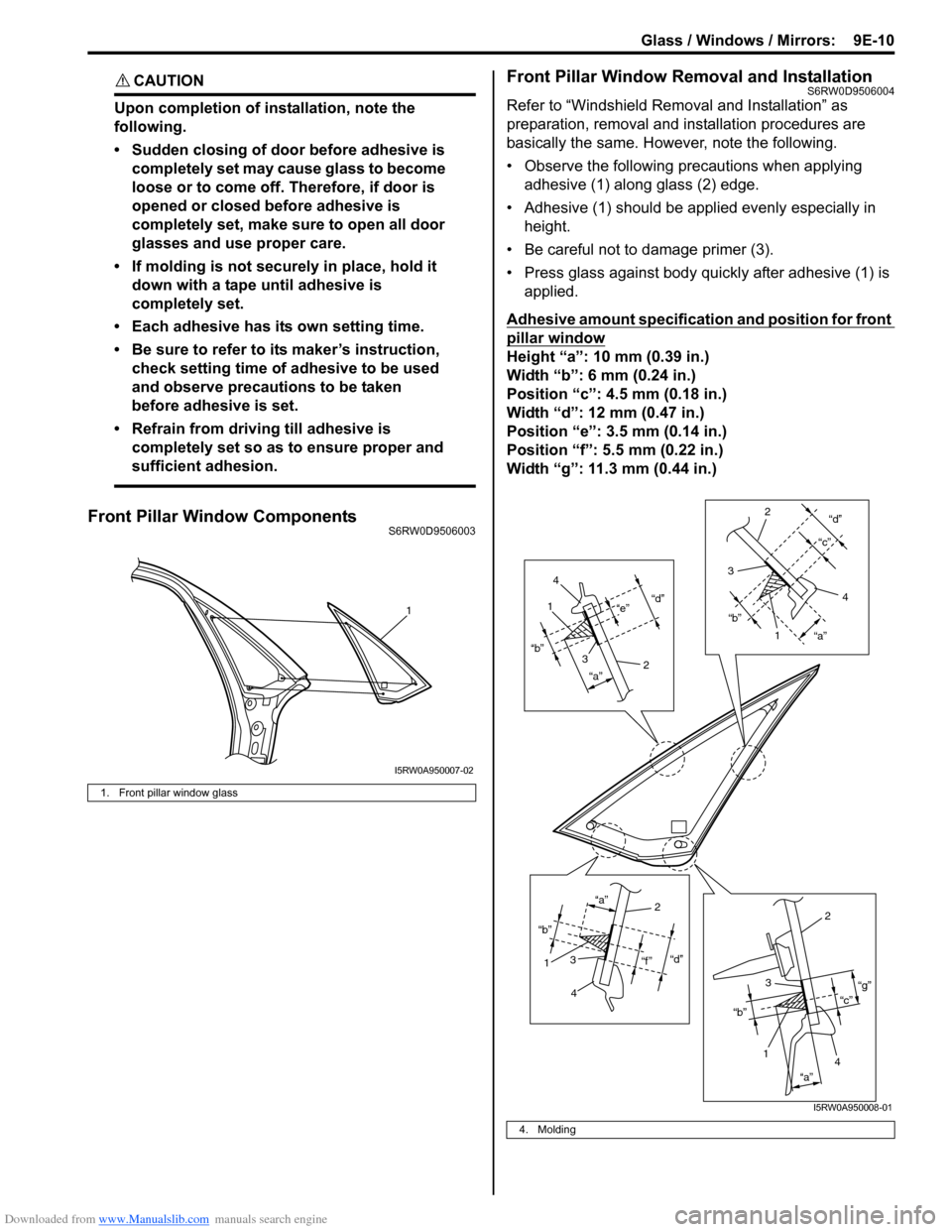
• Observe the following precautions when applying
adhesive (1) along glass (2) edge.
• Adhesive (1) should be applied evenly especially in
height.
• Be careful not to damage primer (3).
• Press glass against body quickly after adhesive (1) is
applied.
Adhesive amount specification and position for front
pillar window
Height “a”: 10 mm (0.39 in.)
Width “b”: 6 mm (0.24 in.)
Position “c”: 4.5 mm (0.18 in.)
Width “d”: 12 mm (0.47 in.)
Position “e”: 3.5 mm (0.14 in.)
Position “f”: 5.5 mm (0.22 in.)
Width “g”: 11.3 mm (0.44 in.)
1. Front pillar window glass
1
I5RW0A950007-02
4. Molding
“d”
“a” “b”“e”1
2 3
4
“d”
“a” “b”“c”
1 2
3
4
“d”
“f ” “a”
“b”12
3
4
“c”“g”
“a” “b”
12
3
4
I5RW0A950008-01
Page 1396 of 1556
Downloaded from www.Manualslib.com manuals search engine 9E-11 Glass / Windows / Mirrors:
Rear Quarter Window ComponentsS6RW0D9506005Rear Quarter Window Removal and InstallationS6RW0D9506006
Refer to “Windshield Removal and Installation” as
preparation, removal and installation procedures are
basically the same. However, note the following.
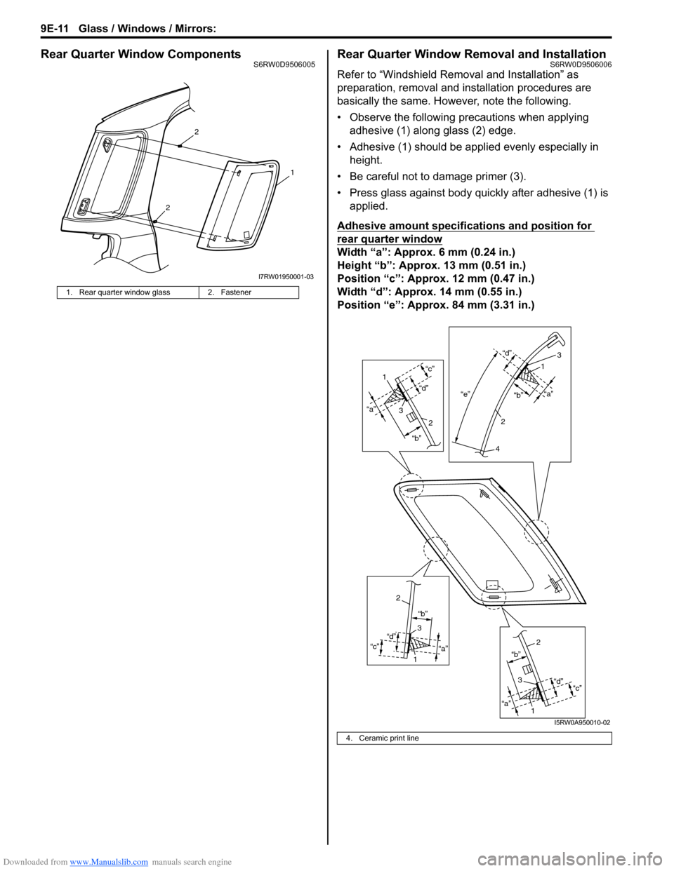
• Observe the following precautions when applying
adhesive (1) along glass (2) edge.
• Adhesive (1) should be applied evenly especially in
height.
• Be careful not to damage primer (3).
• Press glass against body quickly after adhesive (1) is
applied.
Adhesive amount specifications and position for
rear quarter window
Width “a”: Approx. 6 mm (0.24 in.)
Height “b”: Approx. 13 mm (0.51 in.)
Position “c”: Approx. 12 mm (0.47 in.)
Width “d”: Approx. 14 mm (0.55 in.)
Position “e”: Approx. 84 mm (3.31 in.)
1. Rear quarter window glass 2. Fastener
2
2
1
I7RW01950001-03
4. Ceramic print line
“a”
“b”
“d”“c”“e”“a”
“b” “d”
“a” “b”
“d”
“c”
“a”“b”
“d”
“c”
1
3
2
3
1
2
4
2
3
1
2
3
1
I5RW0A950010-02
Page 1397 of 1556
Downloaded from www.Manualslib.com manuals search engine Glass / Windows / Mirrors: 9E-12
Rear End Door Window ComponentsS6RW0D9506007
Rear End Door Glass Removal and InstallationS6RW0D9506008
Refer to “Windshield Removal and Installation” as
preparation, removal and installation procedures are
basically the same. However, note the following.
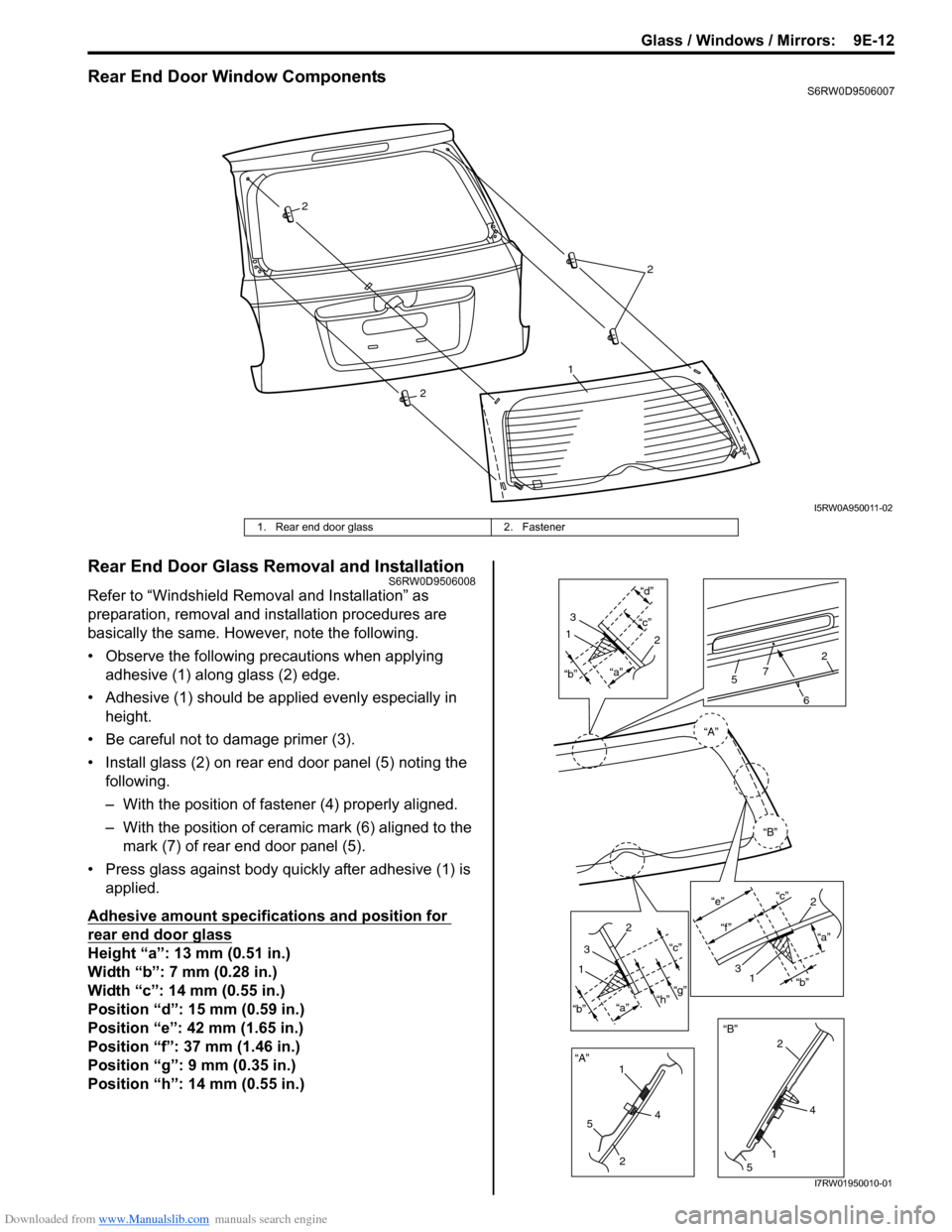
• Observe the following precautions when applying
adhesive (1) along glass (2) edge.
• Adhesive (1) should be applied evenly especially in
height.
• Be careful not to damage primer (3).
• Install glass (2) on rear end door panel (5) noting the
following.
– With the position of fastener (4) properly aligned.
– With the position of ceramic mark (6) aligned to the
mark (7) of rear end door panel (5).
• Press glass against body quickly after adhesive (1) is
applied.
Adhesive amount specifications and position for
rear end door glass
Height “a”: 13 mm (0.51 in.)
Width “b”: 7 mm (0.28 in.)
Width “c”: 14 mm (0.55 in.)
Position “d”: 15 mm (0.59 in.)
Position “e”: 42 mm (1.65 in.)
Position “f”: 37 mm (1.46 in.)
Position “g”: 9 mm (0.35 in.)
Position “h”: 14 mm (0.55 in.)
2
2
1
2
I5RW0A950011-02
1. Rear end door glass 2. Fastener
“A”“a”“c”“d”1
3
12
“a”
“b”“c”
“g”
“h”
1
2
3
“A”
“B”“B” “b”
5
24
15
4 2
6
572
“a” “c”
“e”
“f ”
2
31“b”
I7RW01950010-01
Page 1471 of 1556
Downloaded from www.Manualslib.com manuals search engine Table of Contents 10- i
10
Section 10
CONTENTS
Control Systems
Precautions ............................................... 10-1
Precautions........................................................... 10-1
Precautions for Control Systems......................... 10-1
Body Electrical Control System ........... 10B-1
Precautions......................................................... 10B-1
Precautions in Diagnosing Trouble ................... 10B-1
General Description ........................................... 10B-1
BCM General Description ................................. 10B-1
CAN Communication System Description......... 10B-1
Theft Deterrent Light ......................................... 10B-2
Security Alarm Description (If Equipped) .......... 10B-2
Schematic and Routing Diagram ...................... 10B-3
Body Electrical Control System Wiring Circuit
Diagram .......................................................... 10B-3
Connector Layout Diagram of BCM and
Junction Block ................................................. 10B-6
Component Location ......................................... 10B-7
BCM and Related System Component
Location .......................................................... 10B-7
Diagnostic Information and Procedures .......... 10B-8
BCM Self-Diagnosis Function ........................... 10B-8
Body Electrical Control System Check.............. 10B-9
Scan Tool Data ............................................... 10B-11
DTC Table ....................................................... 10B-13
DTC Check ..................................................... 10B-14
DTC Clearance ............................................... 10B-15
BCM Power Circuit and Ground Circuit Check 10B-16
DTC B1133 (DTC No. 1133): Battery Voltage
Too High ....................................................... 10B-17
DTC B1141 / DTC B1142 (No. 1141 / No.
1142) Outside Air Temperature (Ambient
Temp.) Sensor Circuit Malfunction ................ 10B-18
DTC B1150 (No. 1150): Air Bag
Communication Circuit Malfunction .............. 10B-19
DTC B1157 (No. 1157) Air Bag Deployment
Signal Input ................................................... 10B-20
DTC B1170 (No. 1170): EEPROM Access
Error .............................................................. 10B-20
DTC U0073 (No. 0073): Control Module
Communication Bus Off ................................ 10B-20
DTC U0100 (No. 0100): Lost Communication
with ECM....................................................... 10B-20DTC U0101 (No. 0101): Lost Communication
with TCM ....................................................... 10B-20
DTC U0155 (No. 0155): Lost Communication
with Instrument Panel Cluster (IPC) Control
Module .......................................................... 10B-20
DTC U1144 (No. 1144): Lost Communication
with Keyless Start Control Module ................ 10B-20
Inspection of BCM and Its Circuits .................. 10B-21
Repair Instructions ..........................................10B-28
BCM (Included in Junction Block) Removal
and Installation .............................................. 10B-28
Security Alarm Mode Selection Procedure (If
Equipped) ...................................................... 10B-29
Outside Air Temperature Sensor Removal
and Installation .............................................. 10B-29
Outside Air Temperature Sensor Inspection ... 10B-29
Special Tools and Equipment .........................10B-29
Special Tool .................................................... 10B-29
Immobilizer Control System ................. 10C-1
Precautions.........................................................10C-1
Precautions in Diagnosing Troubles .................10C-1
Precaution in Replacing ECM ...........................10C-1
Precaution in Replacing Ignition Key ................10C-1
Precautions in Handling Immobilizer Control
System ............................................................10C-1
General Description ...........................................10C-2
Immobilizer Control System Introduction ..........10C-2
On-Board Diagnostic System Description
(Self-diagnosis Function)................................10C-2
Schematic and Routing Diagram ......................10C-3
Immobilizer Control System Wiring Circuit
Diagram...........................................................10C-3
Component Location .........................................10C-5
Immobilizer Control System Components
Location...........................................................10C-5
Diagnostic Information and Procedures ..........10C-5
Immobilizer Control System Check ...................10C-5
DTC Check........................................................10C-6
DTC Clearance .................................................10C-6
DTC Table .........................................................10C-7
Scan Tool Data .................................................10C-8
Immobilizer Indicator Light Does Not Come
ON with Ignition Switch ON and Engine Stop ..10C-9