2006 SUZUKI SX4 relay
[x] Cancel search: relayPage 1327 of 1556
Downloaded from www.Manualslib.com manuals search engine Lighting Systems: 9B-8
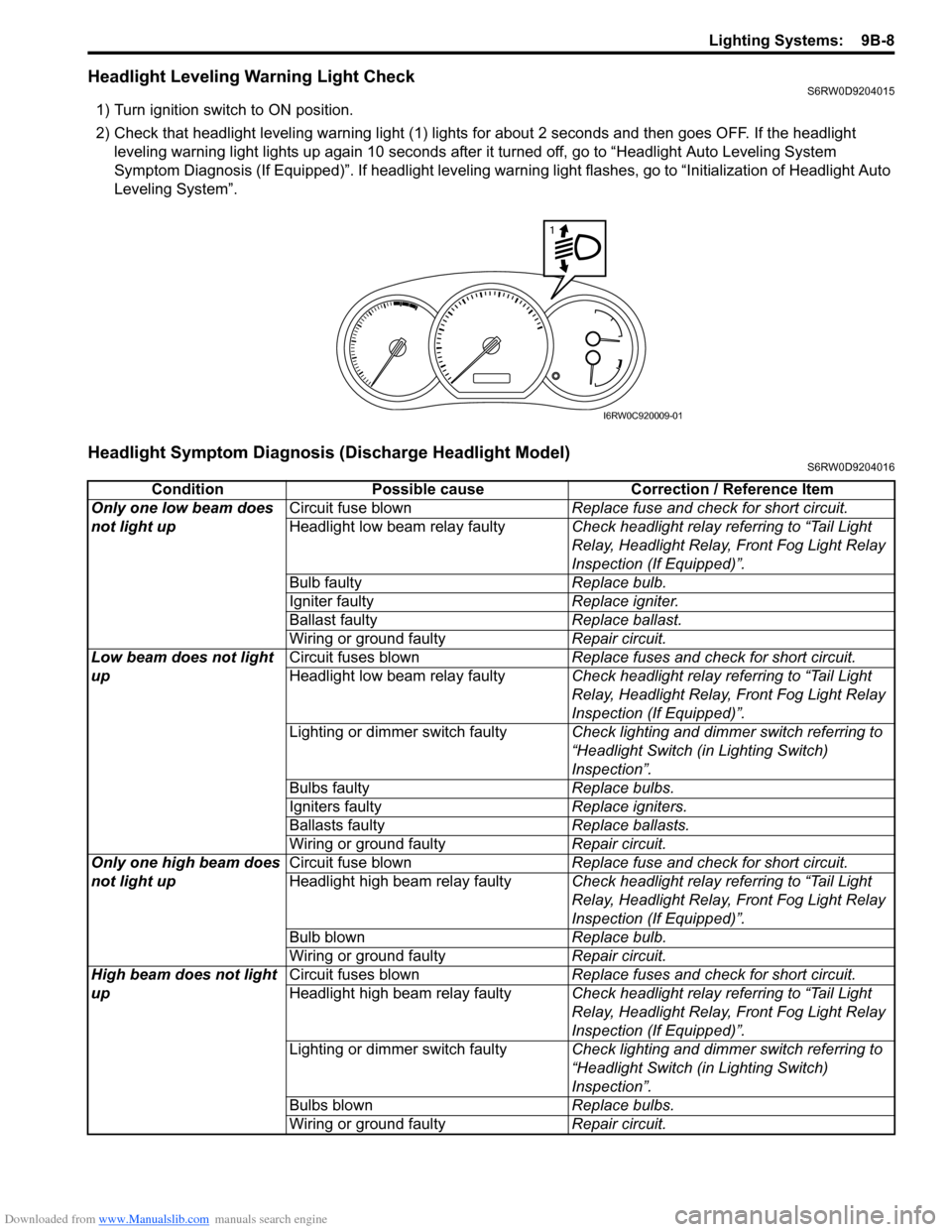
Headlight Leveling Warning Light CheckS6RW0D9204015
1) Turn ignition switch to ON position.
2) Check that headlight leveling warning light (1) lights for about 2 seconds and then goes OFF. If the headlight
leveling warning light lights up again 10 seconds after it turned off, go to “Headlight Auto Leveling System
Symptom Diagnosis (If Equipped)”. If headlight leveling warning light flashes, go to “Initialization of Headlight Auto
Leveling System”.
Headlight Symptom Diagnosis (Discharge Headlight Model)S6RW0D9204016
1
I6RW0C920009-01
Condition Possible cause Correction / Reference Item
Only one low beam does
not light upCircuit fuse blownReplace fuse and check for short circuit.
Headlight low beam relay faultyCheck headlight relay referring to “Tail Light
Relay, Headlight Relay, Front Fog Light Relay
Inspection (If Equipped)”.
Bulb faultyReplace bulb.
Igniter faultyReplace igniter.
Ballast faultyReplace ballast.
Wiring or ground faultyRepair circuit.
Low beam does not light
upCircuit fuses blownReplace fuses and check for short circuit.
Headlight low beam relay faultyCheck headlight relay referring to “Tail Light
Relay, Headlight Relay, Front Fog Light Relay
Inspection (If Equipped)”.
Lighting or dimmer switch faultyCheck lighting and dimmer switch referring to
“Headlight Switch (in Lighting Switch)
Inspection”.
Bulbs faultyReplace bulbs.
Igniters faultyReplace igniters.
Ballasts faultyReplace ballasts.
Wiring or ground faultyRepair circuit.
Only one high beam does
not light upCircuit fuse blownReplace fuse and check for short circuit.
Headlight high beam relay faultyCheck headlight relay referring to “Tail Light
Relay, Headlight Relay, Front Fog Light Relay
Inspection (If Equipped)”.
Bulb blownReplace bulb.
Wiring or ground faultyRepair circuit.
High beam does not light
upCircuit fuses blownReplace fuses and check for short circuit.
Headlight high beam relay faultyCheck headlight relay referring to “Tail Light
Relay, Headlight Relay, Front Fog Light Relay
Inspection (If Equipped)”.
Lighting or dimmer switch faultyCheck lighting and dimmer switch referring to
“Headlight Switch (in Lighting Switch)
Inspection”.
Bulbs blownReplace bulbs.
Wiring or ground faultyRepair circuit.
Page 1328 of 1556

Downloaded from www.Manualslib.com manuals search engine 9B-9 Lighting Systems:
Headlight Symptom diagnosis (Other than Discharge Headlight Model)S6RW0D9204017
Auto-On Headlight System Symptom Diagnosis (If Equipped)S6RW0D9204018
Condition Possible cause Correction / Reference Item
Only one low beam does
not light upCircuit fuse blownReplace fuse and check for short circuit.
Bulb blownReplace bulb.
Headlight low beam relay faulty (if
equipped)Check headlight relay referring to “Tail Light
Relay, Headlight Relay, Front Fog Light Relay
Inspection (If Equipped)”.
Wiring or ground faultyRepair circuit.
Low beam does not light
upCircuit fuse blownReplace fuses and check for short circuit.
Headlight low beam relay faulty (if
equipped)Check headlight relay referring to “Tail Light
Relay, Headlight Relay, Front Fog Light Relay
Inspection (If Equipped)”.
Lighting or dimmer switch faultyCheck lighting and dimmer switch referring to
“Headlight Switch (in Lighting Switch)
Inspection”.
Bulbs blownReplace bulbs.
Wiring or ground faultyRepair circuit.
DRL controller faulty (if equipped)Check system referring to “Inspection of DRL
Controller and Its Circuits (If Equipped)”.
Only one high beam does
not light upCircuit fuse blownReplace fuse and check for short circuit.
Bulb blownReplace bulb.
Headlight high beam relay faulty (if
equipped)Check headlight relay referring to “Tail Light
Relay, Headlight Relay, Front Fog Light Relay
Inspection (If Equipped)”.
Wiring or ground faultyRepair circuit.
High beam does not light
upCircuit fuse blownReplace fuses and check for short circuit.
Headlight high beam relay faulty (if
equipped)Check headlight relay referring to “Tail Light
Relay, Headlight Relay, Front Fog Light Relay
Inspection (If Equipped)”.
Lighting or dimmer switch faultyCheck lighting and dimmer switch referring to
“Headlight Switch (in Lighting Switch)
Inspection”.
Bulbs blownReplace bulbs.
Wiring or ground faultyRepair circuit.
Condition Possible cause Correction / Reference Item
Headlights are not turned
ON or OFF automatically
even after darkened or
lightenedCircuit fuse blownReplace fuse and check for short circuit.
Lighting or dimmer switch faultyCheck lighting and dimmer switch referring to
“Headlight Switch (in Lighting Switch)
Inspection”.
Auto-on headlight sensor faultyCheck auto-on headlight sensor referring to
“Auto-On Headlight Sensor Inspection (If
Equipped)”.
Wiring or ground faultyRepair circuit.
Auto-on headlight controller faultyCheck auto-on headlight controller for function
referring to “Inspection of Auto-On Headlight
Controller and Its Circuit (If Equipped)”.
Page 1330 of 1556
Downloaded from www.Manualslib.com manuals search engine 9B-11 Lighting Systems:
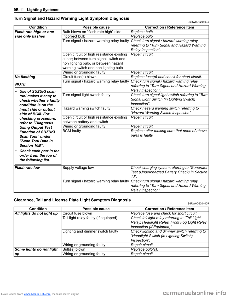
Turn Signal and Hazard Warning Light Symptom DiagnosisS6RW0D9204004
Clearance, Tail and License Plate Light Symptom DiagnosisS6RW0D9204005
Condition Possible cause Correction / Reference Item
Flash rate high or one
side only flashesBulb blown on “flash rate high”-sideReplace bulb.
Incorrect bulbReplace bulb.
Turn signal / hazard warning relay faultyCheck turn signal / hazard warning relay
referring to “Turn Signal and Hazard Warning
Relay Inspection”.
Open circuit or high resistance existing
either; between turn signal switch and
non lighting bulb, or between hazard
warning switch and non lighting bulbRepair circuit.
Wiring or grounding faultyRepair circuit.
No flashing
NOTE
• Use of SUZUKI scan
tool makes it easy to
check whether a faulty
condition is on the
input side or output
side of BCM. For
checking procedure,
refer to “Diagnosis
Using Output Test
Function of SUZUKI
Scan Tool” under
“Scan Tool Data in
Section 10B”.
• Check each part in the
order from the top of
the following list.
Circuit fuse(s) blownReplace fuse(s) and check for short circuit.
Turn signal / hazard warning relay faultyCheck turn signal / hazard warning relay
referring to “Turn Signal and Hazard Warning
Relay Inspection”.
Turn signal light switch faultyCheck turn signal light switch referring to “Turn
Signal Light Switch (in Lighting Switch)
Inspection”.
Hazard warning switch faultyCheck hazard warning switch referring to
“Hazard Warning Switch Inspection”.
Open circuit or high resistance existing
between battery and switchRepair circuit.
Wiring or grounding faultyRepair circuit.
BCM faultyReplace after making sure that none of above
parts is faulty.
Flash rate lowSupply voltage lowCheck charging system referring to “Generator
Test (Undercharged Battery Check) in Section
1J”.
Turn signal / hazard warning relay faultyCheck turn signal / hazard warning relay
referring to “Turn Signal and Hazard Warning
Relay Inspection”.
Condition Possible cause Correction / Reference Item
All lights do not light upCircuit fuse blownReplace fuse and check for short circuit.
Tail light relay faulty (if equipped)Check tail light relay referring to “Tail Light
Relay, Headlight Relay, Front Fog Light Relay
Inspection (If Equipped)”.
Lighting and dimmer switch faultyCheck lighting and dimmer switch referring to
“Headlight Switch (in Lighting Switch)
Inspection”.
Wiring or grounding faultyRepair circuit.
Some lights do not light
upBulb(s) blownReplace bulb(s).
Wiring or grounding faultyRepair circuit.
Page 1331 of 1556
Downloaded from www.Manualslib.com manuals search engine Lighting Systems: 9B-12
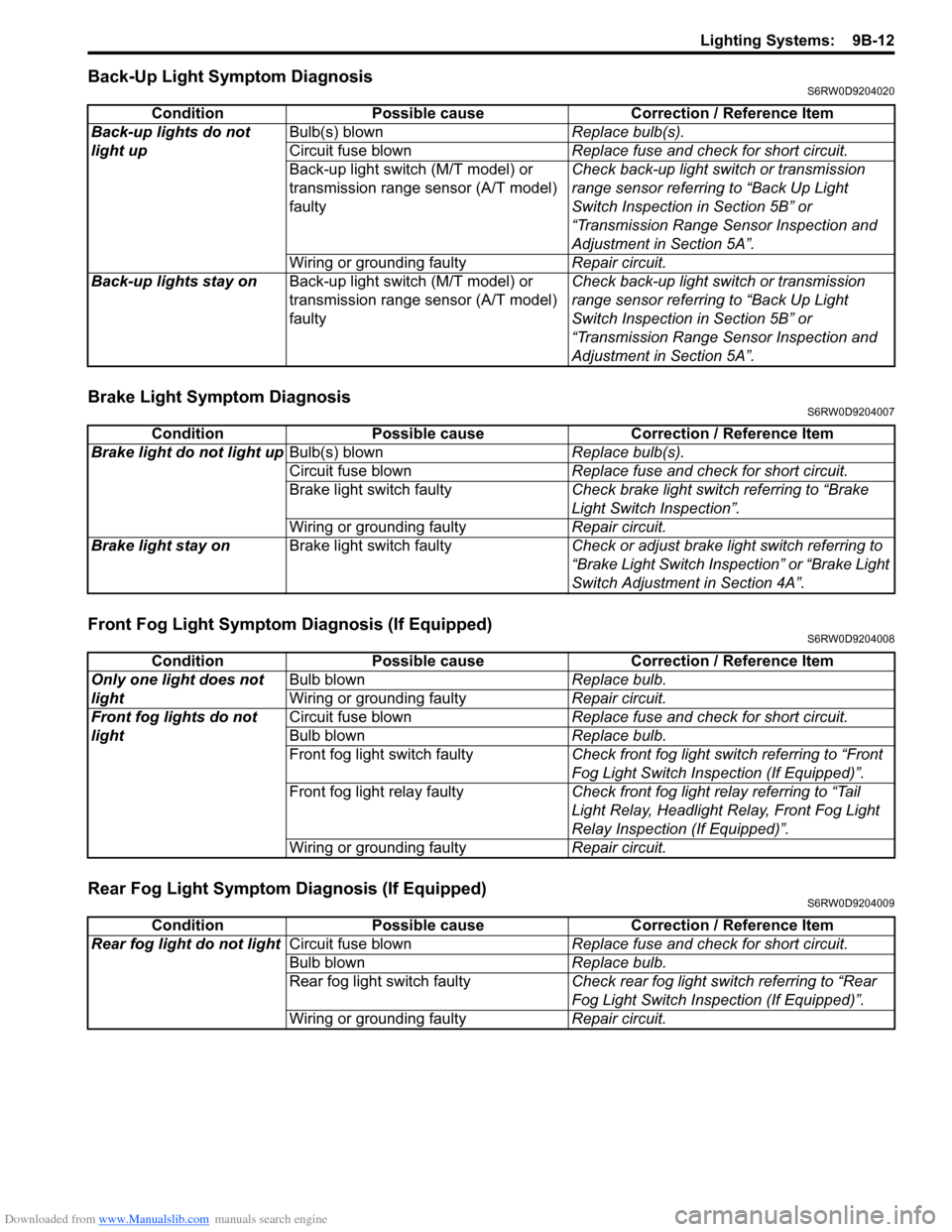
Back-Up Light Symptom DiagnosisS6RW0D9204020
Brake Light Symptom DiagnosisS6RW0D9204007
Front Fog Light Symptom Diagnosis (If Equipped)S6RW0D9204008
Rear Fog Light Symptom Diagnosis (If Equipped)S6RW0D9204009
Condition Possible cause Correction / Reference Item
Back-up lights do not
light upBulb(s) blownReplace bulb(s).
Circuit fuse blownReplace fuse and check for short circuit.
Back-up light switch (M/T model) or
transmission range sensor (A/T model)
faultyCheck back-up light switch or transmission
range sensor referring to “Back Up Light
Switch Inspection in Section 5B” or
“Transmission Range Sensor Inspection and
Adjustment in Section 5A”.
Wiring or grounding faultyRepair circuit.
Back-up lights stay onBack-up light switch (M/T model) or
transmission range sensor (A/T model)
faultyCheck back-up light switch or transmission
range sensor referring to “Back Up Light
Switch Inspection in Section 5B” or
“Transmission Range Sensor Inspection and
Adjustment in Section 5A”.
Condition Possible cause Correction / Reference Item
Brake light do not light upBulb(s) blownReplace bulb(s).
Circuit fuse blownReplace fuse and check for short circuit.
Brake light switch faultyCheck brake light switch referring to “Brake
Light Switch Inspection”.
Wiring or grounding faultyRepair circuit.
Brake light stay onBrake light switch faultyCheck or adjust brake light switch referring to
“Brake Light Switch Inspection” or “Brake Light
Switch Adjustment in Section 4A”.
Condition Possible cause Correction / Reference Item
Only one light does not
lightBulb blownReplace bulb.
Wiring or grounding faultyRepair circuit.
Front fog lights do not
lightCircuit fuse blownReplace fuse and check for short circuit.
Bulb blownReplace bulb.
Front fog light switch faultyCheck front fog light switch referring to “Front
Fog Light Switch Inspection (If Equipped)”.
Front fog light relay faultyCheck front fog light relay referring to “Tail
Light Relay, Headlight Relay, Front Fog Light
Relay Inspection (If Equipped)”.
Wiring or grounding faultyRepair circuit.
Condition Possible cause Correction / Reference Item
Rear fog light do not lightCircuit fuse blownReplace fuse and check for short circuit.
Bulb blownReplace bulb.
Rear fog light switch faultyCheck rear fog light switch referring to “Rear
Fog Light Switch Inspection (If Equipped)”.
Wiring or grounding faultyRepair circuit.
Page 1343 of 1556
Downloaded from www.Manualslib.com manuals search engine Lighting Systems: 9B-24
Turn Signal Light Switch (in Lighting Switch)
Removal and Installation
S6RW0D9206009
For removal and Installation, refer to “Headlight Switch
(in Lighting Switch) Removal and Installation”.
Turn Signal Light Switch (in Lighting Switch)
Inspection
S6RW0D9206010
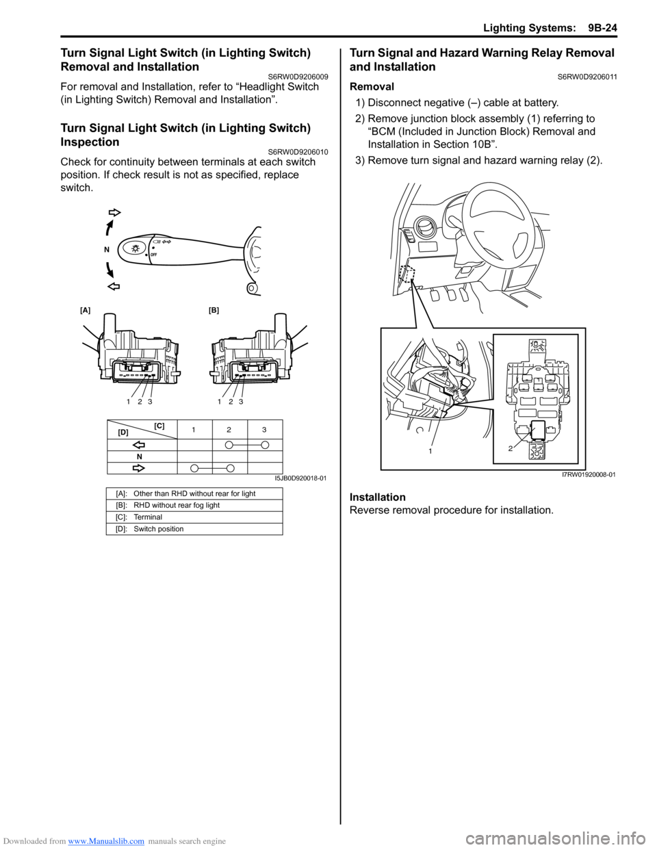
Check for continuity between terminals at each switch
position. If check result is not as specified, replace
switch.
Turn Signal and Hazard Warning Relay Removal
and Installation
S6RW0D9206011
Removal
1) Disconnect negative (–) cable at battery.
2) Remove junction block assembly (1) referring to
“BCM (Included in Junction Block) Removal and
Installation in Section 10B”.
3) Remove turn signal and hazard warning relay (2).
Installation
Reverse removal procedure for installation.
[A]: Other than RHD without rear for light
[B]: RHD without rear fog light
[C]: Terminal
[D]: Switch position
3 12
3 2 13 2 1
[C]
[D]
[A] [B]
N
N
I5JB0D920018-01
2
1
I7RW01920008-01
Page 1344 of 1556
Downloaded from www.Manualslib.com manuals search engine 9B-25 Lighting Systems:
Turn Signal and Hazard Warning Relay
Inspection
S6RW0D9206012
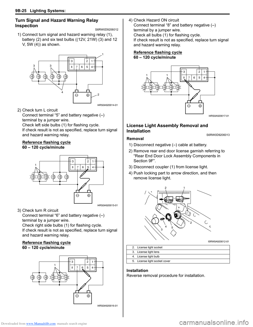
1) Connect turn signal and hazard warning relay (1),
battery (2) and six test bulbs ((12V, 21W) (3) and 12
V, 5W (4)) as shown.
2) Check turn L circuit
Connect terminal “5” and battery negative (–)
terminal by a jumper wire.
Check left side bulbs (1) for flashing cycle.
If check result is not as specified, replace turn signal
and hazard warning relay.
Reference flashing cycle
60 – 120 cycle/minute
3) Check turn R circuit
Connect terminal “6” and battery negative (–)
terminal by a jumper wire.
Check right side bulbs (1) for flashing cycle.
If check result is not as specified, replace turn signal
and hazard warning relay.
Reference flashing cycle
60 – 120 cycle/minute4) Check Hazard ON circuit
Connect terminal “8” and battery negative (–)
terminal by a jumper wire.
Check all bulbs (1) for flashing cycle.
If check result is not as specified, replace turn signal
and hazard warning relay.
Reference flashing cycle
60 – 120 cycle/minute
License Light Assembly Removal and
Installation
S6RW0D9206013
Removal
1) Disconnect negative (–) cable at battery.
2) Remove rear end door license garnish referring to
“Rear End Door Lock Assembly Components in
Section 9F”.
3) Disconnect coupler (1) from license light.
4) Push locking part to arrow direction, and then
remove license light.
Installation
Reverse removal procedure for installation.
2 4
33
3
87
12
654
1
I4RS0A920014-01
13
87
12
654
I4RS0A920015-01
3
87
12
6541
I4RS0A920016-01
2. License light socket
3. License light lens
4. License light bulb
5. License light socket cover
3
87
12
6
5411
I4RS0A920017-01
2
34
5
2 1
I5RW0A920012-01
Page 1351 of 1556
Downloaded from www.Manualslib.com manuals search engine Lighting Systems: 9B-32
Illumination Cancel Switch Inspection (If
Equipped)
S6RW0D9206022
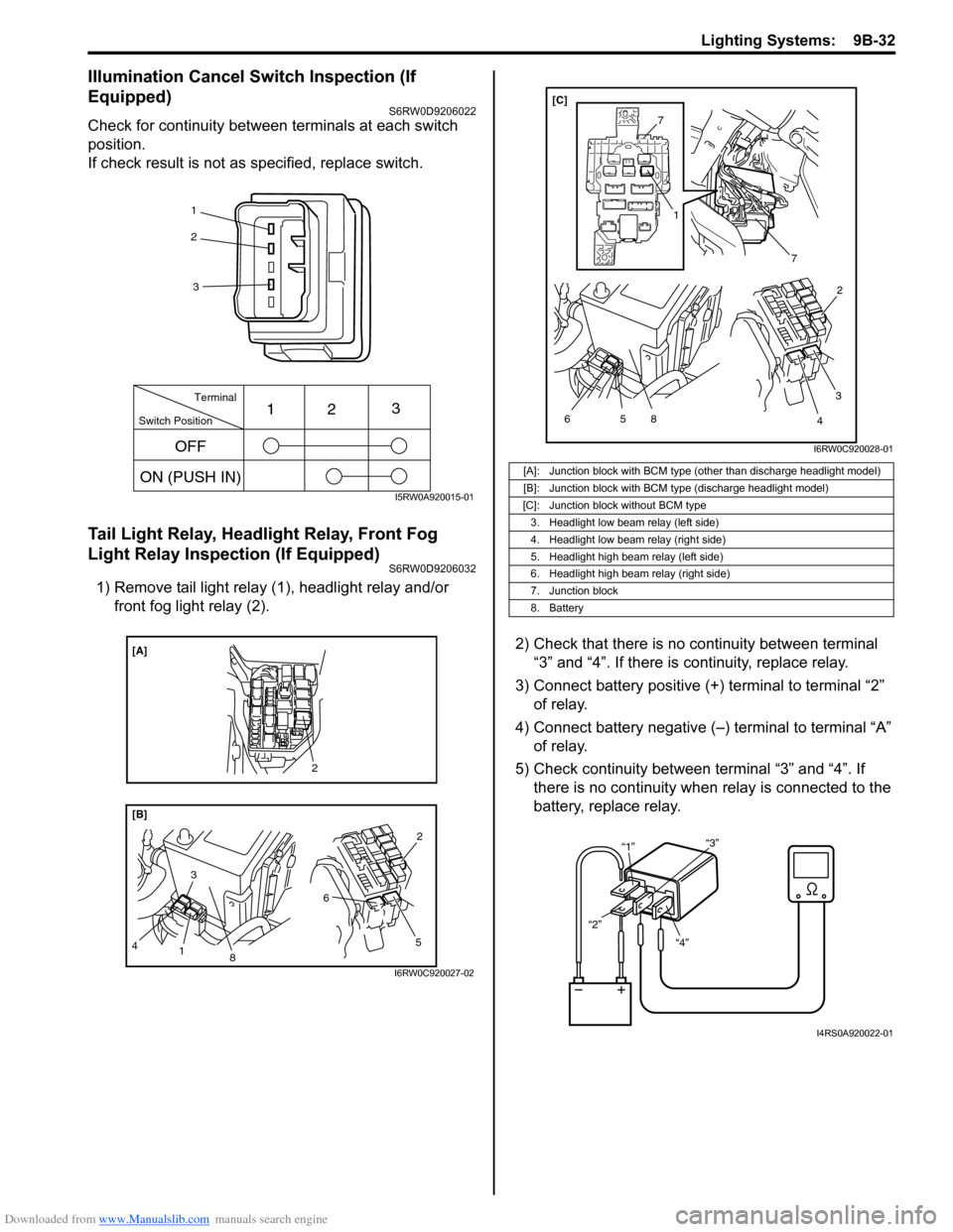
Check for continuity between terminals at each switch
position.
If check result is not as specified, replace switch.
Tail Light Relay, Headlight Relay, Front Fog
Light Relay Inspection (If Equipped)
S6RW0D9206032
1) Remove tail light relay (1), headlight relay and/or
front fog light relay (2).
2) Check that there is no continuity between terminal
“3” and “4”. If there is continuity, replace relay.
3) Connect battery positive (+) terminal to terminal “2”
of relay.
4) Connect battery negative (–) terminal to terminal “A”
of relay.
5) Check continuity between terminal “3” and “4”. If
there is no continuity when relay is connected to the
battery, replace relay.
1
2
3
Switch PositionTerminal
ON (PUSH IN)123
OFF
I5RW0A920015-01
8
[B] [A]
3
4
1
5 62
2
I6RW0C920027-02
[A]: Junction block with BCM type (other than discharge headlight model)
[B]: Junction block with BCM type (discharge headlight model)
[C]: Junction block without BCM type
3. Headlight low beam relay (left side)
4. Headlight low beam relay (right side)
5. Headlight high beam relay (left side)
6. Headlight high beam relay (right side)
7. Junction block
8. Battery
7
7
5 6
1
8
3
42 [C]
I6RW0C920028-01
“4” “2”“1”“3”
I4RS0A920022-01
Page 1362 of 1556
Downloaded from www.Manualslib.com manuals search engine 9C-10 Instrumentation / Driver Info. / Horn:
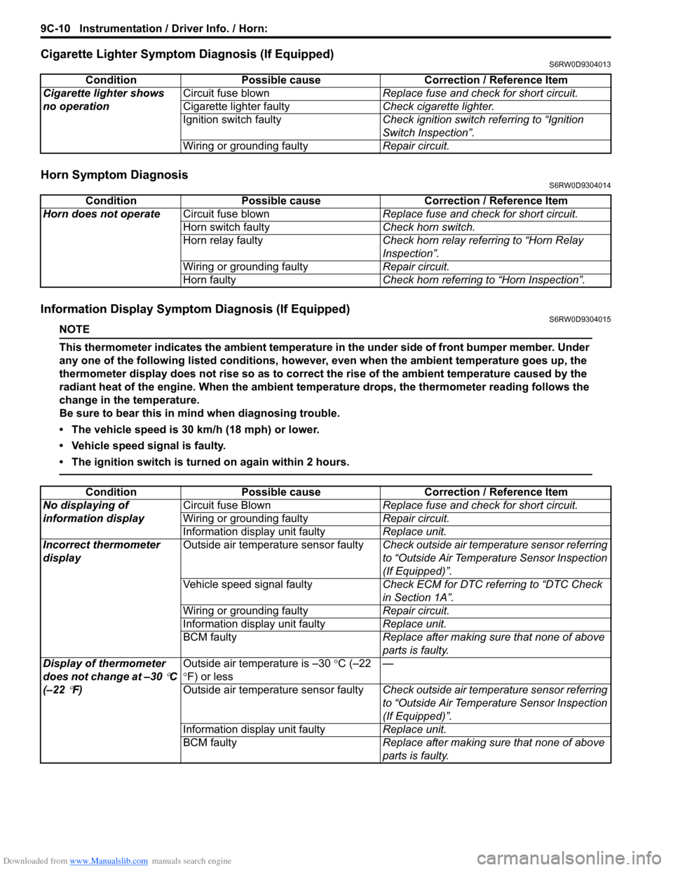
Cigarette Lighter Symptom Diagnosis (If Equipped)S6RW0D9304013
Horn Symptom DiagnosisS6RW0D9304014
Information Display Symptom Diagnosis (If Equipped)S6RW0D9304015
NOTE
This thermometer indicates the ambient temperature in the under side of front bumper member. Under
any one of the following listed conditions, however, even when the ambient temperature goes up, the
thermometer display does not rise so as to correct the rise of the ambient temperature caused by the
radiant heat of the engine. When the ambient temperature drops, the thermometer reading follows the
change in the temperature.
Be sure to bear this in mind when diagnosing trouble.
• The vehicle speed is 30 km/h (18 mph) or lower.
• Vehicle speed signal is faulty.
• The ignition switch is turned on again within 2 hours.
Condition Possible cause Correction / Reference Item
Cigarette lighter shows
no operationCircuit fuse blownReplace fuse and check for short circuit.
Cigarette lighter faultyCheck cigarette lighter.
Ignition switch faultyCheck ignition switch referring to “Ignition
Switch Inspection”.
Wiring or grounding faultyRepair circuit.
Condition Possible cause Correction / Reference Item
Horn does not operateCircuit fuse blownReplace fuse and check for short circuit.
Horn switch faultyCheck horn switch.
Horn relay faultyCheck horn relay referring to “Horn Relay
Inspection”.
Wiring or grounding faultyRepair circuit.
Horn faultyCheck horn referring to “Horn Inspection”.
Condition Possible cause Correction / Reference Item
No displaying of
information displayCircuit fuse BlownReplace fuse and check for short circuit.
Wiring or grounding faultyRepair circuit.
Information display unit faultyReplace unit.
Incorrect thermometer
displayOutside air temperature sensor faultyCheck outside air temperature sensor referring
to “Outside Air Temperature Sensor Inspection
(If Equipped)”.
Vehicle speed signal faultyCheck ECM for DTC referring to “DTC Check
in Section 1A”.
Wiring or grounding faultyRepair circuit.
Information display unit faultyReplace unit.
BCM faultyReplace after making sure that none of above
parts is faulty.
Display of thermometer
does not change at –30
°C
(–22
°F)Outside air temperature is –30 °C (–22
°F) or less—
Outside air temperature sensor faultyCheck outside air temperature sensor referring
to “Outside Air Temperature Sensor Inspection
(If Equipped)”.
Information display unit faultyReplace unit.
BCM faultyReplace after making sure that none of above
parts is faulty.