2006 SUZUKI SX4 relay
[x] Cancel search: relayPage 1372 of 1556
Downloaded from www.Manualslib.com manuals search engine 9C-20 Instrumentation / Driver Info. / Horn:
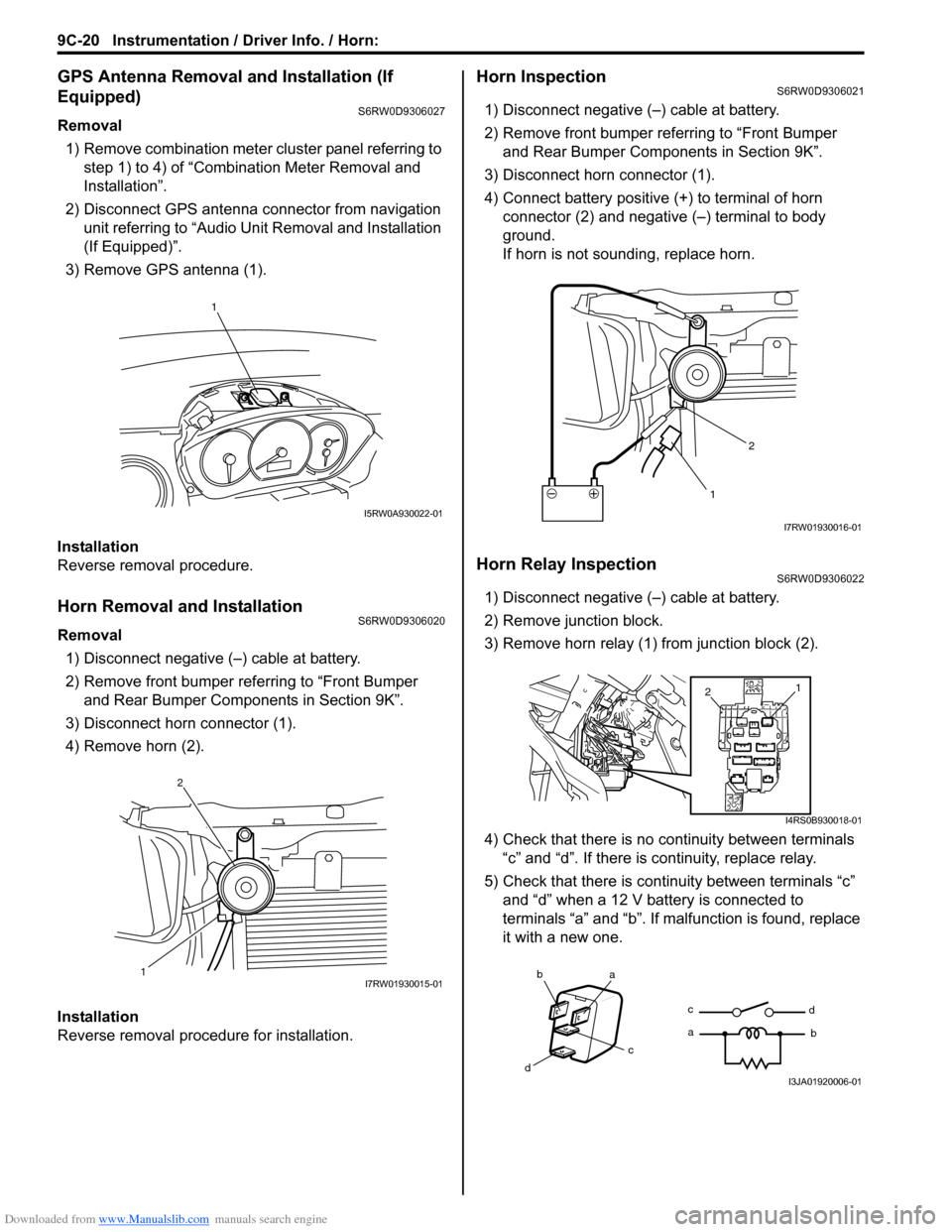
GPS Antenna Removal and Installation (If
Equipped)
S6RW0D9306027
Removal
1) Remove combination meter cluster panel referring to
step 1) to 4) of “Combination Meter Removal and
Installation”.
2) Disconnect GPS antenna connector from navigation
unit referring to “Audio Unit Removal and Installation
(If Equipped)”.
3) Remove GPS antenna (1).
Installation
Reverse removal procedure.
Horn Removal and InstallationS6RW0D9306020
Removal
1) Disconnect negative (–) cable at battery.
2) Remove front bumper referring to “Front Bumper
and Rear Bumper Components in Section 9K”.
3) Disconnect horn connector (1).
4) Remove horn (2).
Installation
Reverse removal procedure for installation.
Horn InspectionS6RW0D9306021
1) Disconnect negative (–) cable at battery.
2) Remove front bumper referring to “Front Bumper
and Rear Bumper Components in Section 9K”.
3) Disconnect horn connector (1).
4) Connect battery positive (+) to terminal of horn
connector (2) and negative (–) terminal to body
ground.
If horn is not sounding, replace horn.
Horn Relay InspectionS6RW0D9306022
1) Disconnect negative (–) cable at battery.
2) Remove junction block.
3) Remove horn relay (1) from junction block (2).
4) Check that there is no continuity between terminals
“c” and “d”. If there is continuity, replace relay.
5) Check that there is continuity between terminals “c”
and “d” when a 12 V battery is connected to
terminals “a” and “b”. If malfunction is found, replace
it with a new one.
1
I5RW0A930022-01
12I7RW01930015-01
12
I7RW01930016-01
1
2
I4RS0B930018-01
ba
c
dc
ad
bI3JA01920006-01
Page 1375 of 1556
Downloaded from www.Manualslib.com manuals search engine Wipers / Washers: 9D-1
Body, Cab and Accessories
Wipers / Washers
Diagnostic Information and Procedures
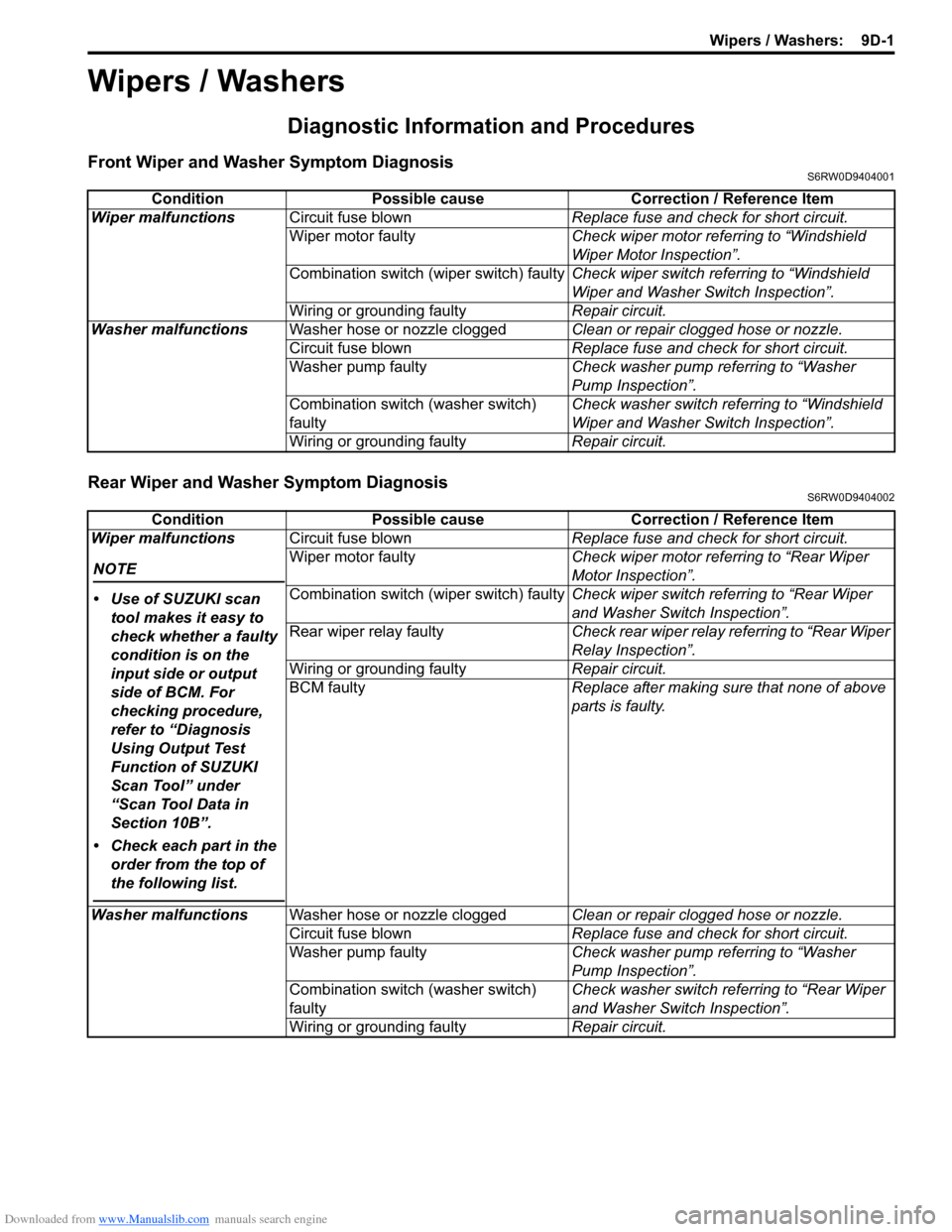
Front Wiper and Washer Symptom DiagnosisS6RW0D9404001
Rear Wiper and Washer Symptom DiagnosisS6RW0D9404002
Condition Possible cause Correction / Reference Item
Wiper malfunctionsCircuit fuse blownReplace fuse and check for short circuit.
Wiper motor faultyCheck wiper motor referring to “Windshield
Wiper Motor Inspection”.
Combination switch (wiper switch) faultyCheck wiper switch referring to “Windshield
Wiper and Washer Switch Inspection”.
Wiring or grounding faultyRepair circuit.
Washer malfunctionsWasher hose or nozzle cloggedClean or repair clogged hose or nozzle.
Circuit fuse blownReplace fuse and check for short circuit.
Washer pump faultyCheck washer pump referring to “Washer
Pump Inspection”.
Combination switch (washer switch)
faultyCheck washer switch referring to “Windshield
Wiper and Washer Switch Inspection”.
Wiring or grounding faultyRepair circuit.
Condition Possible cause Correction / Reference Item
Wiper malfunctions
NOTE
• Use of SUZUKI scan
tool makes it easy to
check whether a faulty
condition is on the
input side or output
side of BCM. For
checking procedure,
refer to “Diagnosis
Using Output Test
Function of SUZUKI
Scan Tool” under
“Scan Tool Data in
Section 10B”.
• Check each part in the
order from the top of
the following list.
Circuit fuse blownReplace fuse and check for short circuit.
Wiper motor faultyCheck wiper motor referring to “Rear Wiper
Motor Inspection”.
Combination switch (wiper switch) faultyCheck wiper switch referring to “Rear Wiper
and Washer Switch Inspection”.
Rear wiper relay faultyCheck rear wiper relay referring to “Rear Wiper
Relay Inspection”.
Wiring or grounding faultyRepair circuit.
BCM faultyReplace after making sure that none of above
parts is faulty.
Washer malfunctionsWasher hose or nozzle cloggedClean or repair clogged hose or nozzle.
Circuit fuse blownReplace fuse and check for short circuit.
Washer pump faultyCheck washer pump referring to “Washer
Pump Inspection”.
Combination switch (washer switch)
faultyCheck washer switch referring to “Rear Wiper
and Washer Switch Inspection”.
Wiring or grounding faultyRepair circuit.
Page 1376 of 1556
![SUZUKI SX4 2006 1.G Service Workshop Manual Downloaded from www.Manualslib.com manuals search engine 9D-2 Wipers / Washers:
Repair Instructions
Wipers and Washers ComponentsS6RW0D9406001
115
6
(b)
(a) 1 1
(b)
2
1314
14[A]
14
1215
(c)
(b)
(a)
3 SUZUKI SX4 2006 1.G Service Workshop Manual Downloaded from www.Manualslib.com manuals search engine 9D-2 Wipers / Washers:
Repair Instructions
Wipers and Washers ComponentsS6RW0D9406001
115
6
(b)
(a) 1 1
(b)
2
1314
14[A]
14
1215
(c)
(b)
(a)
3](/manual-img/20/7612/w960_7612-1375.png)
Downloaded from www.Manualslib.com manuals search engine 9D-2 Wipers / Washers:
Repair Instructions
Wipers and Washers ComponentsS6RW0D9406001
115
6
(b)
(a) 1 1
(b)
2
1314
14[A]
14
1215
(c)
(b)
(a)
32
4
710
10
10 11118
16
9
16
I7RW01940001-03
1. Windshield wiper blade 8. Washer pump for rear washer 15. Windshield wiper bolt
:Tighten bolts in specified order.
2. Windshield wiper arm 9. Washer tank 16. Washer tank bolt
3. Windshield wiper motor 10. Washer hose[A]: Junction block viewed from relay
side
4. Windshield wiper link 11. Washer nozzle : 18 N⋅m (1.8 kgf-m, 13.0 lb-ft)
Page 1377 of 1556
Downloaded from www.Manualslib.com manuals search engine Wipers / Washers: 9D-3
Washer Tank and Washer Pump Removal and
Installation
S6RW0D9406002
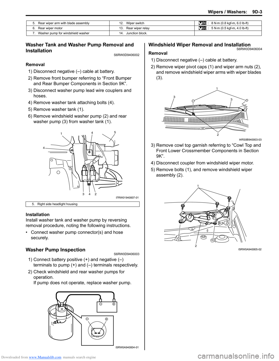
Removal
1) Disconnect negative (–) cable at battery.
2) Remove front bumper referring to “Front Bumper
and Rear Bumper Components in Section 9K”.
3) Disconnect washer pump lead wire couplers and
hoses.
4) Remove washer tank attaching bolts (4).
5) Remove washer tank (1).
6) Remove windshield washer pump (2) and rear
washer pump (3) from washer tank (1).
Installation
Install washer tank and washer pump by reversing
removal procedure, noting the following instructions.
• Connect washer pump connector(s) and hose
securely.
Washer Pump InspectionS6RW0D9406003
1) Connect battery positive (+) and negative (–)
terminals to pump (+) and (–) terminals respectively.
2) Check windshield and rear washer pumps for
operation.
If pump does not operate, replace washer pump.
Windshield Wiper Removal and InstallationS6RW0D9406004
Removal
1) Disconnect negative (–) cable at battery.
2) Remove wiper pivot caps (1) and wiper arm nuts (2),
and remove windshield wiper arms with wiper blades
(3).
3) Remove cowl top garnish referring to “Cowl Top and
Front Lower Crossmember Components in Section
9K”.
4) Disconnect coupler from windshield wiper motor.
5) Remove bolts (1), and remove windshield wiper
assembly (2).
5. Rear wiper arm with blade assembly 12. Wiper switch : 8 N⋅m (0.8 kgf-m, 6.0 lb-ft)
6. Rear wiper motor 13. Rear wiper relay : 5 N⋅m (0.5 kgf-m, 4.0 lb-ft)
7. Washer pump for windshield washer 14. Junction block.
5. Right side headlight housing
1
4
34245
I7RW01940007-01
I5RW0A940004-01
1
3 3
2
I4RS0B940003-03
21I5RW0A940005-02
Page 1383 of 1556
Downloaded from www.Manualslib.com manuals search engine Wipers / Washers: 9D-9
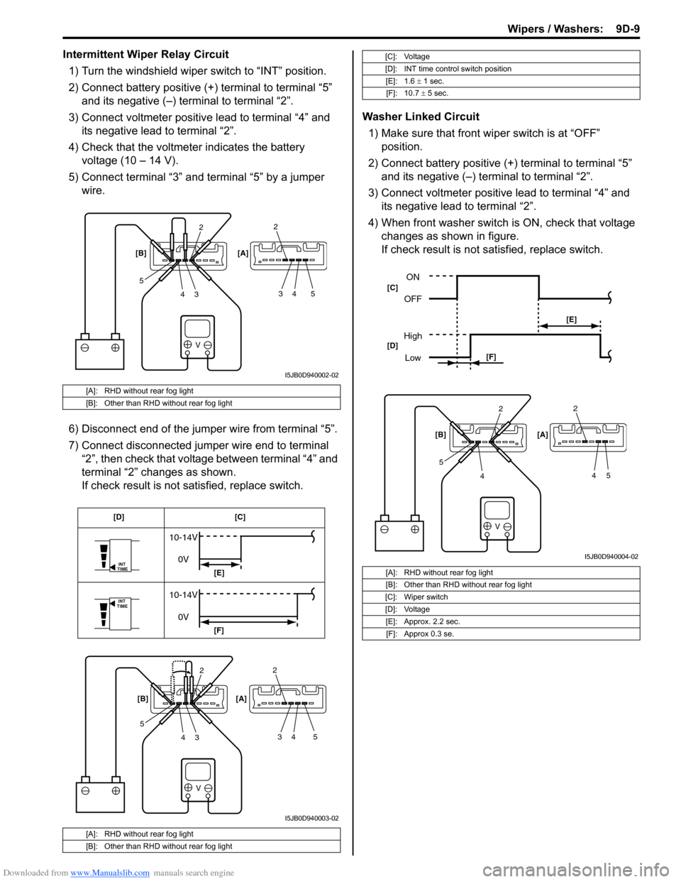
Intermittent Wiper Relay Circuit
1) Turn the windshield wiper switch to “INT” position.
2) Connect battery positive (+) terminal to terminal “5”
and its negative (–) terminal to terminal “2”.
3) Connect voltmeter positive lead to terminal “4” and
its negative lead to terminal “2”.
4) Check that the voltmeter indicates the battery
voltage (10 – 14 V).
5) Connect terminal “3” and terminal “5” by a jumper
wire.
6) Disconnect end of the jumper wire from terminal “5”.
7) Connect disconnected jumper wire end to terminal
“2”, then check that voltage between terminal “4” and
terminal “2” changes as shown.
If check result is not satisfied, replace switch.Washer Linked Circuit
1) Make sure that front wiper switch is at “OFF”
position.
2) Connect battery positive (+) terminal to terminal “5”
and its negative (–) terminal to terminal “2”.
3) Connect voltmeter positive lead to terminal “4” and
its negative lead to terminal “2”.
4) When front washer switch is ON, check that voltage
changes as shown in figure.
If check result is not satisfied, replace switch.
[A]: RHD without rear fog light
[B]: Other than RHD without rear fog light
[A]: RHD without rear fog light
[B]: Other than RHD without rear fog light
V
2
3 4 52
34 5 [B] [A]
I5JB0D940002-02
V
INT
TIME
INT
TIME
10-14V
0V
10-14V
0V
2
3 4 52
34 5 [B] [A][C] [D]
[E]
[F]
I5JB0D940003-02
[C]: Voltage
[D]: INT time control switch position
[E]: 1.6 ± 1 sec.
[F]: 10.7 ± 5 sec.
[A]: RHD without rear fog light
[B]: Other than RHD without rear fog light
[C]: Wiper switch
[D]: Voltage
[E]: Approx. 2.2 sec.
[F]: Approx 0.3 se.
V
2
4 52
45 [B] [A]
ON
OFF
High
Low
[E]
[F] [C]
[D]
I5JB0D940004-02
Page 1384 of 1556
Downloaded from www.Manualslib.com manuals search engine 9D-10 Wipers / Washers:
Rear Wiper and Washer Switch Removal and
Installation
S6RW0D9406010
For removal and installation, refer to “Windshield Wiper
and Washer Switch Removal and Installation”.
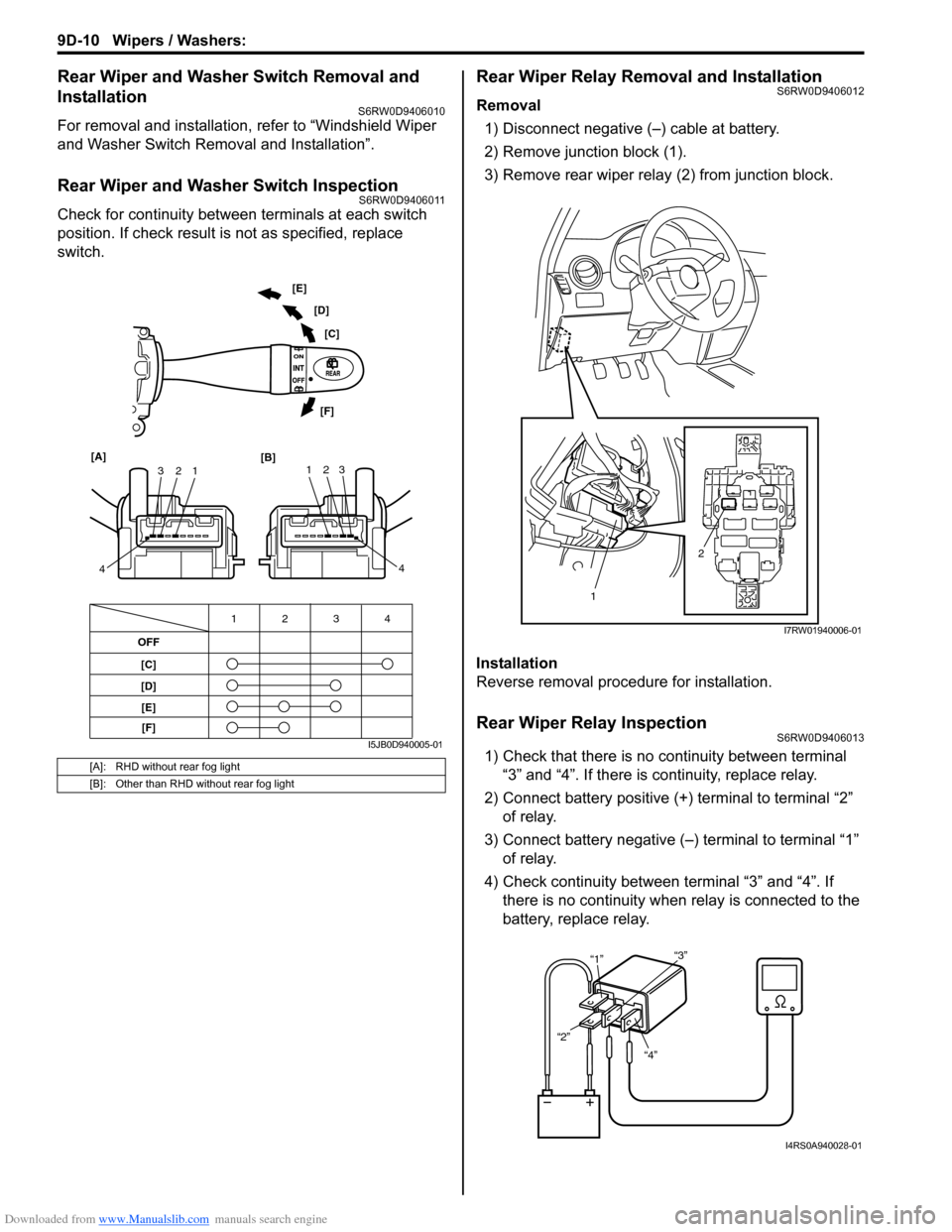
Rear Wiper and Washer Switch InspectionS6RW0D9406011
Check for continuity between terminals at each switch
position. If check result is not as specified, replace
switch.
Rear Wiper Relay Removal and InstallationS6RW0D9406012
Removal
1) Disconnect negative (–) cable at battery.
2) Remove junction block (1).
3) Remove rear wiper relay (2) from junction block.
Installation
Reverse removal procedure for installation.
Rear Wiper Relay InspectionS6RW0D9406013
1) Check that there is no continuity between terminal
“3” and “4”. If there is continuity, replace relay.
2) Connect battery positive (+) terminal to terminal “2”
of relay.
3) Connect battery negative (–) terminal to terminal “1”
of relay.
4) Check continuity between terminal “3” and “4”. If
there is no continuity when relay is connected to the
battery, replace relay.[A]: RHD without rear fog light
[B]: Other than RHD without rear fog light
OFF
[C]
[D]4 3 12
1 2 3
4 [A]
[B]123
4 [C] [D] [E]
[F]
[E]
[F]
I5JB0D940005-01
2
1
I7RW01940006-01
“4” “2”“1”“3”
I4RS0A940028-01
Page 1388 of 1556
Downloaded from www.Manualslib.com manuals search engine 9E-3 Glass / Windows / Mirrors:
Diagnostic Information and Procedures
Rear End door Window Defogger Symptom DiagnosisS6RW0D9504001
NOTE
• Use of SUZUKI scan tool makes it easy to check whether a faulty condition is on the input side or
output side of BCM. For checking procedure, refer to “Diagnosis Using Output Test Function of
SUZUKI Scan Tool” under “Scan Tool Data in Section 10B”.
• Check each part in the order from the top of the following list.
Power Window Control System Symptom DiagnosisS6RW0D9504002
Condition Possible cause Correction / Reference Item
Rear end door window
defogger does not
operateCircuit fuse blownReplace fuse and check for short circuit.
Rear end door window defogger switch
faultyCheck rear end door window defogger switch
referring to “Rear End Door Window Defogger
Switch Inspection”.
Rear end door window defogger relay
faultyCheck rear end door window defogger relay
referring to “Rear End Door Window Defogger
Relay Inspection”.
Defogger wire faultyCheck defogger wire referring to “Rear End
Door Window Defogger Wire Inspection”.
Wiring or grounding faultyRepair circuit.
BCM faultyReplace after making sure that none of above
parts is faulty.
Condition Possible cause Correction / Reference Item
All power windows do not
operateCircuit fuse blownReplace fuse and check for short circuit.
Power window main switch faultyCheck power window main switch referring to
“Power Window Main Switch Inspection”.
Ignition switch faultyCheck ignition switch referring to “Ignition
Switch Inspection in Section 9C”.
Wiring or grounding faultyRepair circuit.
Only one power window
does not operatePower window main switch faultyCheck power window main switch referring to
“Power Window Main Switch Inspection”.
Power window sub switch faultyCheck power window sub switch referring to
“Power Window Sub Switch Inspection”.
Wiring and/or coupler faultyCheck wiring and/or coupler.
Power window regulator faultyCheck window regulator.
Power window motor faultyCheck power window motor.
Wiring or grounding faultyRepair circuit.
Driver side door glass
fails to perform auto-up /
auto-down function
(Pinching Prevention
Function Model)Power window main switch faultyCheck power window main switch referring to
“Power Window Main Switch Inspection”.
Power window motor faultyCheck power window motor referring to “Pulse
Sensor and Its Circuit Inspection (Pinching
Prevention Function Model)”.
Wiring or grounding faultyRepair circuit.
Driver side door glass
fails to lower back even
when a foreign matter is
pinched (Pinching
Prevention Function
Model)Power window main switch has not been
initializedExecute the initial setting of power window
main switch referring to “Power Window Main
Switch Initialization (Pinching Prevention
Function Model)”.
Power window main switch faultyCheck power window main switch referring to
“Power Window Main Switch Inspection”.
Power window motor faultyCheck power window motor referring to “Pulse
Sensor and Its Circuit Inspection (Pinching
Prevention Function Model)”.
Page 1390 of 1556
Downloaded from www.Manualslib.com manuals search engine 9E-5 Glass / Windows / Mirrors:
Door Mirror Heater Symptom Diagnosis (If Equipped)S6RW0D9504004
NOTE
• Use of SUZUKI scan tool makes it easy to check whether a faulty condition is on the input side or
output side of BCM. For checking procedure, refer to “Diagnosis Using Output Test Function of
SUZUKI Scan Tool” under “Scan Tool Data in Section 10B”.
• Check each part in the order from the top of the following list.
Repair Instructions
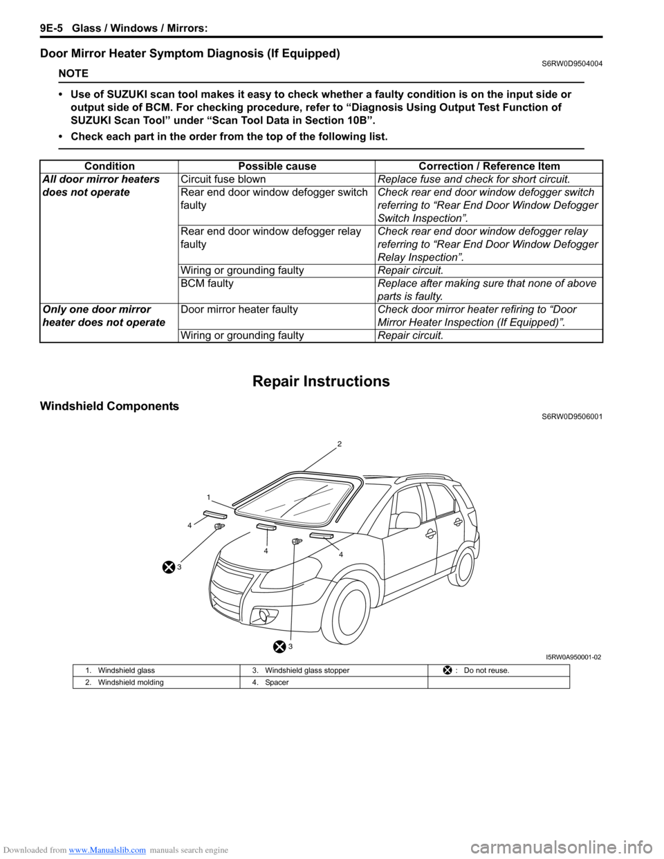
Windshield ComponentsS6RW0D9506001
Condition Possible cause Correction / Reference Item
All door mirror heaters
does not operateCircuit fuse blownReplace fuse and check for short circuit.
Rear end door window defogger switch
faultyCheck rear end door window defogger switch
referring to “Rear End Door Window Defogger
Switch Inspection”.
Rear end door window defogger relay
faultyCheck rear end door window defogger relay
referring to “Rear End Door Window Defogger
Relay Inspection”.
Wiring or grounding faultyRepair circuit.
BCM faultyReplace after making sure that none of above
parts is faulty.
Only one door mirror
heater does not operateDoor mirror heater faultyCheck door mirror heater refiring to “Door
Mirror Heater Inspection (If Equipped)”.
Wiring or grounding faultyRepair circuit.
3 31
2
44
4
I5RW0A950001-02
1. Windshield glass 3. Windshield glass stopper : Do not reuse.
2. Windshield molding 4. Spacer