2006 SUZUKI SX4 Oil pan bolt
[x] Cancel search: Oil pan boltPage 360 of 1556
Downloaded from www.Manualslib.com manuals search engine 1E-4 Engine Lubrication System:
Oil Pan and Oil Pump Strainer Removal and
Installation
S6RW0D1506002
Removal
1) Remove oil level gauge.
2) Drain engine oil by removing drain plug.
3) For 4WD model, dismount transfer referring to
“Transfer Dismounting and Remounting in Section
3C”.
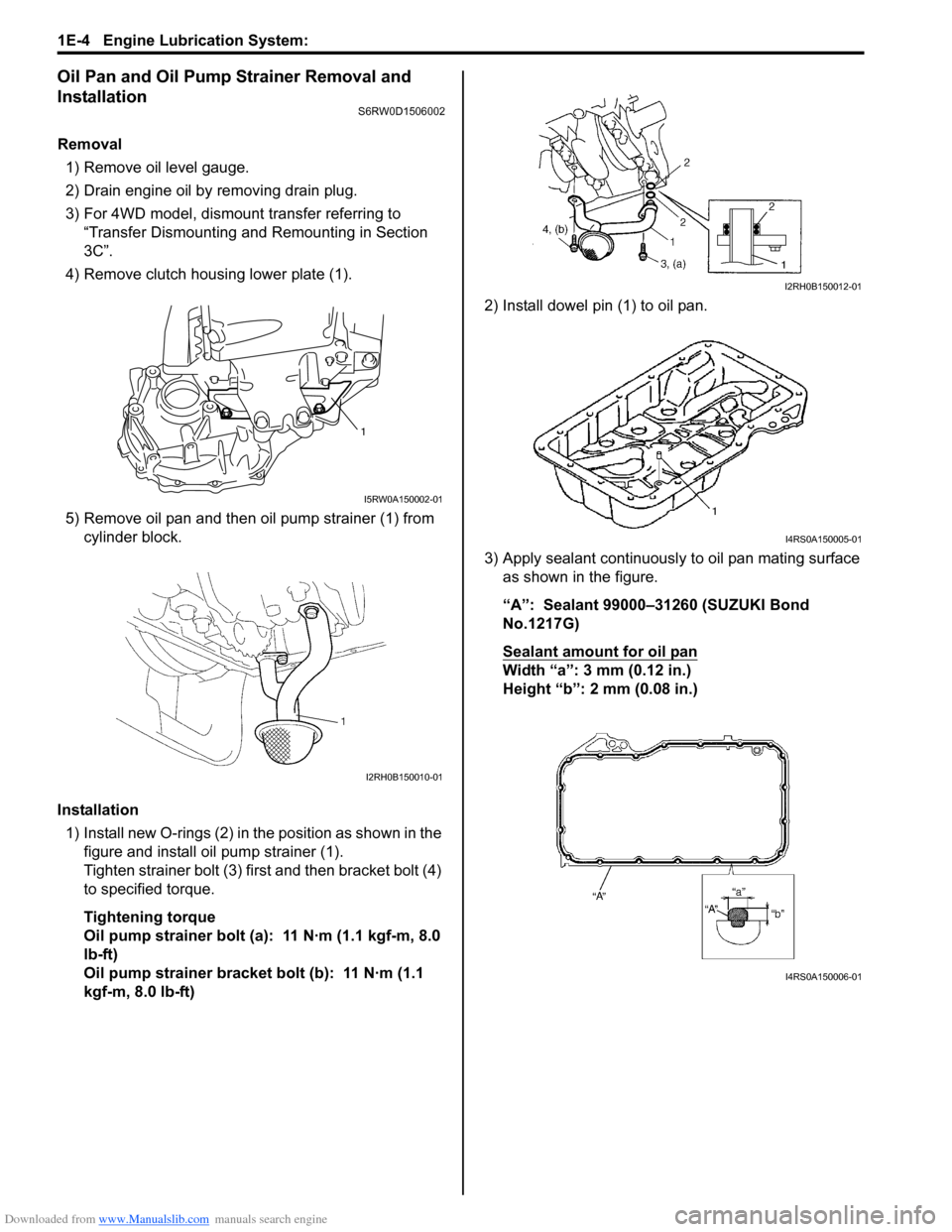
4) Remove clutch housing lower plate (1).
5) Remove oil pan and then oil pump strainer (1) from
cylinder block.
Installation
1) Install new O-rings (2) in the position as shown in the
figure and install oil pump strainer (1).
Tighten strainer bolt (3) first and then bracket bolt (4)
to specified torque.
Tightening torque
Oil pump strainer bolt (a): 11 N·m (1.1 kgf-m, 8.0
lb-ft)
Oil pump strainer bracket bolt (b): 11 N·m (1.1
kgf-m, 8.0 lb-ft)2) Install dowel pin (1) to oil pan.
3) Apply sealant continuously to oil pan mating surface
as shown in the figure.
“A”: Sealant 99000–31260 (SUZUKI Bond
No.1217G)
Sealant amount for oil pan
Width “a”: 3 mm (0.12 in.)
Height “b”: 2 mm (0.08 in.)
1
I5RW0A150002-01
I2RH0B150010-01
I2RH0B150012-01
I4RS0A150005-01
I4RS0A150006-01
Page 361 of 1556

Downloaded from www.Manualslib.com manuals search engine Engine Lubrication System: 1E-5
4) Install oil pan to cylinder block temporarily.
5) Insert dowel pin (1) in hole (2) of oil pan in order to
locate oil pan precisely.
NOTE
Dowel pin is available as a spare part (part
number: 04211–13189).
6) After fitting oil pan to cylinder block, run in securing
bolts and start tightening at the center: move wrench
outward, tightening one bolt at a time. Tighten bolts
and nuts to specified torque.
Tightening torque
Oil pan bolt (M6) (a): 11 N·m (1.1 kgf-m, 8.0 lb-ft)
Oil pan bolt (M10) (c): 55 N·m (5.5 kgf-m, 40.0 lb-
ft)
Oil pan nut (e): 11 N·m (1.1 kgf-m, 8.0 lb-ft)
7) After applying engine oil to drain plug, install new
gasket and drain plug to oil pan.
Tighten drain plug to specified torque.
Tightening torque
Oil pan drain plug (b): 35 N·m (3.5 kgf-m, 25.5 lb-
ft)
8) Tighten transaxle stiffener bolts to specified torque.
Tightening torque
Transaxle stiffener bolt (d): 55 N·m (5.5 kgf-m,
40.0 lb-ft)9) Install clutch housing lower plate (1) and then tighten
clutch housing lower plate bolt to specified torque.
Tightening torque
Clutch housing lower plate bolt (a): 11 N·m (1.1
kgf-m, 8.0 lb-ft)
10) For 4WD model, remount transfer referring to
“Transfer Dismounting and Remounting in Section
3C”.
11) Install oil level gauge.
12) Refill engine with engine oil referring to “Engine Oil
and Filter Change in Section 0B”.
13) Verify that there is no engine oil leakage and exhaust
gas leakage at each connection.
Oil Pan and Oil Pump Strainer CleaningS6RW0D1506003
• Clean sealing surface between oil pan and cylinder
block.
Remove oil, old sealant, and dust from sealing
surface.
• Clean oil pump strainer screen (1).
21I4RS0A150007-01
(a)
(b)
(c)(e)
(d)I4RS0A150008-01
1,(a)
I5RW0A150003-01
I2RH0B150016-01
Page 365 of 1556
Downloaded from www.Manualslib.com manuals search engine Engine Lubrication System: 1E-9
Specifications
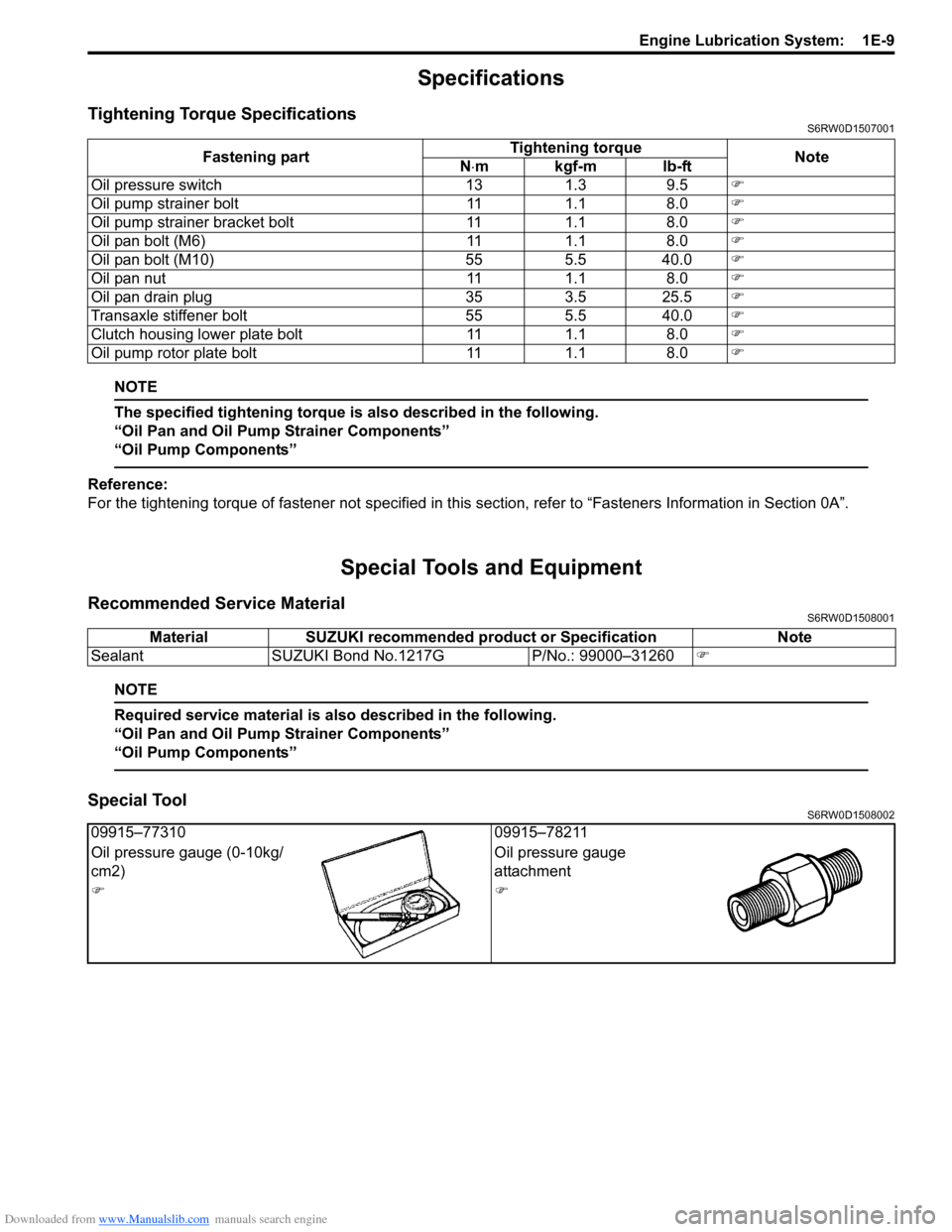
Tightening Torque SpecificationsS6RW0D1507001
NOTE
The specified tightening torque is also described in the following.
“Oil Pan and Oil Pump Strainer Components”
“Oil Pump Components”
Reference:
For the tightening torque of fastener not specified in this section, refer to “Fasteners Information in Section 0A”.
Special Tools and Equipment
Recommended Service MaterialS6RW0D1508001
NOTE
Required service material is also described in the following.
“Oil Pan and Oil Pump Strainer Components”
“Oil Pump Components”
Special ToolS6RW0D1508002
Fastening partTightening torque
Note
N⋅mkgf-mlb-ft
Oil pressure switch 13 1.3 9.5)
Oil pump strainer bolt 11 1.1 8.0)
Oil pump strainer bracket bolt 11 1.1 8.0)
Oil pan bolt (M6) 11 1.1 8.0)
Oil pan bolt (M10) 55 5.5 40.0)
Oil pan nut 11 1.1 8.0)
Oil pan drain plug 35 3.5 25.5)
Transaxle stiffener bolt 55 5.5 40.0)
Clutch housing lower plate bolt 11 1.1 8.0)
Oil pump rotor plate bolt 11 1.1 8.0)
Material SUZUKI recommended product or Specification Note
Sealant SUZUKI Bond No.1217G P/No.: 99000–31260)
09915–77310 09915–78211
Oil pressure gauge (0-10kg/
cm2)Oil pressure gauge
attachment
))
Page 532 of 1556

Downloaded from www.Manualslib.com manuals search engine 3B-35 Differential:
Rear Differential ComponentsS6RW0D3206013
4 5
9
2
30
6
(a)13
12
(a)
3
A
3A
141617 2118
29
3A
1(b)
22
1217G
101217G
11
8OIL
15OIL
19 20OIL
23OIL
25OIL27OIL
27OIL
25OIL
19OIL18
26 28
OIL
26OIL23OIL
24OIL
(c)
14
7
I5RW0A320026-02
1. Flange nut 13. Differential cover bolt 25. Differential gear
2. Companion flange 14. Spacer 26. Spring washer
3. Oil seal
: Apply grease 99000-25010 to oil seal lip.15. Rear bearing 27. Thrust washer
4. Coupling front bearing 16. Shim 28. Pinion shaft
5. Coupling case
: Apply sealant 99000-31260 to mating surface of carrier and coupling
case.17. Bevel pinion 29. Pinion shaft pin
6. Coupling assembly
: Never disassemble.18. Shim 30. Coupling case bolt
7. Snap ring 19. Differential side bearing : 23 N⋅m (2.3 kgf-m, 17.0 lb-ft)
8. Bevel pinion nut
: Tighten nut so as rotation torque of bevel pinion to be in specified value.20. Bevel gear : 125 N⋅m (12.5 kgf-m, 90.5 lb-ft)
9. Front bearing 21. Differential case : 78 N⋅m (7.8 kgf-m, 56.5 lb-ft)
10. Differential carrier
: Apply sealant 99000-31260 to mating surface of carrier and rear cover.22. Bevel gear bolt : Do not reuse.
11. Coupling air temperature sensor 23. Pinion washer : Apply differential oil.
12. Differential cover 24. Pinion
Page 543 of 1556

Downloaded from www.Manualslib.com manuals search engine Differential: 3B-46
26) Clean mating surface of differential carrier (1) and
differential cover, apply sealant to carrier as shown
in figure by such amount that its section is 1.5 mm
(0.059 in.) in diameter, mate differential cover with
differential carrier, and then tighten bolts to specified
torque.
“A”: Sealant 99000–31260 (SUZUKI Bond
No.1217G)
Tightening torque
Differential cover bolt: 23 N·m (2.3 kgf-m, 17.0
lb-ft)
27) Assemble coupling case as follows.
a) Install bearing using special tool and hydraulic
press.
Special tool
(A): 09913–75830
b) Install snap ring using snap ring pliers.
c) Apply grease to oil seal lip, install oil seal (2) to
coupling case (1) using special tool as shown in
figure.
NOTE
Install oil seal horizontally to surface of
coupling case.
“A”: Grease 99000–25010 (SUZUKI Super
Grease A)
Distance between case and oil seal “a”
: 1.5 – 2.5 mm (0.06 – 0.10 in.)
Special tool
(A): 09913–7581028) Install spacer (1) to coupling assembly (2) as shown
in figure.
29) Install grommet of coupling harness into groove of
coupling case and then install coupling assembly by
using hydraulic press.
30) Install companion flange to pinion, and then hold
companion flange with special tool and tighten flange
nut.
Tightening torque
Flange nut: 110 N·m (11.0 kgf-m, 79.5 lb-ft)
Special tool
(A): 09930–40113
“A”
1
I5RW0A320058-02
(A)
I5RW0A320059-02
(A)
1 12, “A”“a”
I5RW0A320060-02
12
12
I5RW0A320065-01
(A)
I5RW0A320061-01
Page 544 of 1556

Downloaded from www.Manualslib.com manuals search engine 3B-47 Differential:
31) Clean mating surface of differential carrier (1) and
coupling case (2), apply sealant to carrier as shown
in figure by such amount that its section is 1.5 mm
(0.059 in.) in diameter, mate coupling case with
differential carrier as shown in figure, and then
tighten bolts to specified torque.
“A”: Sealant 99000–31260 (SUZUKI Bond
No.1217G)
Tightening torque
Coupling case bolt (a): 23 N·m (2.3 kgf-m, 17.0
lb-ft)
NOTE
Install coupling pin (3) by fitting it to groove
(4) of coupling case.
32) Apply grease to oil seal lip, and then install oil seals
(1) to rear differential (2) using special tool as shown
in figure.
NOTE
Install oil seal horizontally to surface of rear
differential case.
“A”: Grease 99000–25010 (SUZUKI Super
Grease A)
Distance between rear differential and oil seal
“a”
: 1.0 – 2.0 mm (0.04 – 0.08 in.)
Special tool
(A): 09913–75810
33) Install drive shaft flange.
34) Install rear mounting bracket to rear differential
referring to “Front Mounting Arm and/or Rear
Mounting Bracket Assembly Removal and
Installation”.
Rear Differential InspectionS6RW0D3206015
• Check companion flange for wear or damage.
• Check bearings for wear or discoloration.
• Check differential carrier for cracks.
• Check drive bevel pinion and bevel gear for wear or
cracks.
• Check side gears, pinion gears and pinion shaft for
wear or damage.
• Check side gear spline for wear or damage.
1 4
3 2“A”
(a)
I5RW0A320062-04
(A)
2 21, “A”
“a”
I5RW0A320063-02
Page 578 of 1556

Downloaded from www.Manualslib.com manuals search engine 4A-7 Brake Control System and Diagnosis:
Repair Instructions
Brake Pedal ComponentsS6RW0D4106018
CAUTION!
If equipped Brake Pedal Foot Protection
System, never disassemble brake pedal
assembly. Disassemble will spoil its original
function. If faulty condition is found, replace
it with new one.
Brake Pedal Free Height InspectionS6RW0D4106001
1) Check brake pedal free height. If it is not within
specification, check and adjust following item 2) and
6).
Brake pedal free height “a” from carpet
111 – 131 mm (4.4 – 5.1 in.)
2) Check measurement between booster mounting
surface and center of clevis pin hole. When booster
push rod clevis has been reinstalled, it is important
that the measurement is adjusted (refer to “Brake
Booster Inspection”).
3) Check brake light switch position. Adjust it if it is out
of specification.
4) Check pedal for dent.
5) Check brake booster for installation.6) Check brake booster push rod for length.
Brake Pedal Play InspectionS6RW0D4106002
Pedal play should be within the following specification. If
out of specification, check brake light switch for proper
installation position and adjust if necessary.
Also check pedal shaft bolt and booster clevis pin
installation for looseness and replace if defective.
Brake pedal play
“a”
: 1 – 8 mm (0.04 – 0.31 in.)
Excessive Pedal Travel InspectionS6RW0D4106003
1) Start engine.
2) Depress brake pedal a few times.
3) With brake pedal depressed with approximately 300
N (30 kg, 66 lbs) load, measure brake pedal to wall
(dash panel silencer) clearance “a”. If clearance is
out of specification, possible causes are as follows.
If clearance “a” is less than specification, the most
possible cause is that air is in lines or brake fluid
leakage.
Should clearance “a” remain less than specification
even after bleeding of system, other possible but
infrequent cause is malfunction of booster push rod
length out of adjustment.
• Bleed brake system. Refer to “Air Bleeding of
Brake System”.
Brake pedal arm to wall clearance
“a”
When pedal is depressed at 300 N (30 kg, 66 lbs)
: Over 40 mm (1.57 in.)
[A]: A/T model : 13 N⋅m (1.3 kgf-m, 9.5 lb-ft)
1. Brake pedal : 23 N⋅m (2.3 kgf-m, 16.5 lb-ft)
2. Brake pedal bracket
I6RW0C410004-01
I6RW0C410005-01
“a”I3RH0A410010-01
I6RW0C410006-01
Page 650 of 1556

Downloaded from www.Manualslib.com manuals search engine 5A-2 Automatic Transmission/Transaxle:
CAUTION!
• Keep component parts in group for each
subassembly and avoid mixing them up.
• Clean all parts with cleaning solvent
thoroughly and air dry them.
• Use kerosene or automatic transaxle fluid
as cleaning solvent.
• Do not use wiping cloths or rags to clean
or dry parts.
• All oil passages should be blown out and
checked to make sure that they are not
obstructed.
• Keep face and eyes away from solvent
spray while air blowing parts.
• Check mating surface for irregularities and
remove them, if any, and clean it again.
• Soak new clutch discs and brake discs in
transaxle fluid for at least 2 hours before
assembly.
• Replace all gaskets and O-ring with new
ones.
• Apply automatic transaxle fluid to all O-
rings.
• When installing seal ring, be careful so that
it is not expanded excessively, extruded or
caught.
• Replace oil seals that are removed and
apply grease to their lips.
• Before installing, be sure to apply
automatic transaxle fluid to sliding, rolling
and thrusting surface of all component
part. Also after installation, make sure to
check each part for proper operation.
• Always use torque wrench when
tightening bolts.
• A new discs should be soaked in ATF at least 2 hours
before use.Part Inspection and Correction Table
Part Inspect for Correction
Casted part,
machined partSmall flaw, burr Remove with oil
stone.
Deep or grooved
flawReplace part.
Clogged fluid
passageClean with air or
wire.
Flaw on installing
surface, residual
gasketRemove with oil
stone or replace
part.
Crack Replace part.
Bearing Unsmooth rotation Replace.
Streak, pitting, flaw,
crackReplace.
Bushing, thrust
washerFlaw, burr, wear,
burningReplace.
Oil seal, gasket Flawed or
hardened seal ringReplace.
Worn seal ring on
its periphery or sideReplace.
Piston seal ring, oil
seal, gasket, etc.Replace.
Gear Flaw, burr Replace.
Worn gear tooth Replace.
Splined part Burr, flaw, torsion Correct with oil
stone or replace.
Snap ring Wear, flaw,
distortionReplace.
No interference Replace.
Thread Burr Replace.
Damage Replace.
Spring Settling, sign of
burningReplace.
Friction plate Wear, burning,
distortion,
damaged clawReplace.
Separator
plate, retaining
plateWear, burning,
distortion,
damaged clawReplace.
Sealing
surface (where
lip contacts)Flaw, rough
surface, stepped
wear, foreign
materialReplace.