Page 875 of 1556

Downloaded from www.Manualslib.com manuals search engine Steering Wheel and Column: 6B-6
3) Install steering column upper cover (1) and lower
cover (2).
CAUTION!
When installing covers, be careful so that
each lead wire is not caught between covers.
Otherwise, each lead wire is damaged.
4) Install steering wheel to steering column. Refer to
“Steering Wheel Removal and Installation”.
5) Connect negative (–) cable to battery.
6) Enable air bag system referring to “Enabling Air Bag
System in Section 8B”.
Centering Contact Coil Cable AssemblyS6RW0D6206004
1) Check that vehicle’s wheels (front tires) are set at
straight-ahead position.
2) Check that ignition switch is at LOCK position.
3) Turn contact coil counterclockwise slowly with a light
force till contact coil will not turn any further.
NOTE
Contact coil can turn about 5 turns at the
maximum, that is, if it is at the center
position, can turn about two and a half turns
both clockwise and counterclockwise.
4) From the position where contact coil became unable
to turn any further (it stopped), turn it back clockwise
about two and a half rotations and align center mark
with alignment mark (1).
Contact Coil Cable Assembly InspectionS6RW0D6206005
Refer to “Contact Coil Cable and Its Circuit Check in
Section 8B”.
Steering Column Removal and InstallationS6RW0D6206008
CAUTION!
Once the steering column is removed from
the vehicle, the column is extremely
susceptible to damage.
• Dropping the column assembly on its end
could collapse the steering shaft or loosen
the plastic shear pins which maintain
column length.
• Leaning on the column assembly could
cause it to bend or deform.
Any of the damage could impair the column’s
collapsible design.
Steering column mounting nuts should not
be loosened with steering shaft joint upper
side bolt tightened as this could cause
damage to shaft joint bearing.
NOTE
When servicing steering column or any
column-mounted component, remove
steering wheel. But when removing steering
column simply to gain access to instrument
panel components, leave steering wheel
installed on steering column.
3. Standard screw 4. Tapping screw
2
1
3
4
I6RW0B620003-01
I4RS0A620012-01
1
I4RS0A620013-01
Page 968 of 1556

Downloaded from www.Manualslib.com manuals search engine 7B-28 Air Conditioning System: Manual Type
Evaporator Temperature Sensor InspectionS6RW0D7216011
Check resistance between terminals of evaporator
temperature sensor (1).
If check results are as not specified, replace evaporator
temperature sensor.
Evaporator temperature sensor resistance
0 °C (32 °F): 6.6 – 6.8 kΩ
25 °C (77 °F): 2.0 – 2.1 kΩ
Expansion Valve Removal and InstallationS6RW0D7216012
Removal
1) Recover refrigerant from the A/C system with
recovery and recycling equipment referring to
“Recovery” in “Operation Procedure for Refrigerant
Charge”.
2) Loosen a bolt (1) and remove pipes from expansion
valve (2).
3) Loosen bolts (3) and remove expansion valve.
Installation
Reverse removal procedure noting the following
instructions.
• Apply compressor oil to O-ring of expansion valve and
pipes.
• Tighten expansion valve bolts to specified torque.
Tightening torque
Expansion valve bolt: 4.5 N·m (0.45 kgf-m, 3.5 lb-
ft)
• Evacuate and charge the A/C system referring to
“Evacuation” and “Charge” in “Operation Procedure
for Refrigerant Charge”.
Expansion Valve InspectionS6RW0D7216013
Refer to “A/C System Performance Inspection”.
[A]: Resistance
[B]: Temperature
(kΩ)
6.75
2.00
0
3225
77 [A]
[B]
(˚C)
(˚F)
1
I7RW01721020-01
1
22 3
I4RS0A720028-01
Page 977 of 1556

Downloaded from www.Manualslib.com manuals search engine Air Conditioning System: Manual Type 7B-37
Specifications
Tightening Torque SpecificationsS6RW0D7217001
NOTE
The specified tightening torque is also described in the following.
“A/C System Major Components Location”
“Compressor Assembly Components”
Reference:
For the tightening torque of fastener not specified in this section, refer to “Fasteners Information in Section 0A”.
Special Tools and Equipment
Recommended Service MaterialS6RW0D7218001
NOTE
Required service material is also described in the following.
“HVAC Unit Components”
“Compressor Assembly Components”
Special ToolS6RW0D7218002
Fastening partTightening torque
Note
N⋅mkgf-mlb-ft
Expansion valve bolt 4.5 0.45 3.5)
A/C refrigerant pressure sensor 11 1.1 8.0)
Compressor mounting bolt 25 2.5 18.0)
Armature plate nut 16 1.6 11.5)
Relief valve 8 0.8 6.0)
Material SUZUKI recommended product or Specification Note
Compressor oil MATSUSHITADENKI GU10 P/No.: 99000–99015–
00A)
Silicon sealant SUZUKI SILICON SEALANT KE-
347W (100g)P/No.: 99000–34220)
09900–06107 09990–06020
Snap ring pliers (opening
type)Manifold gauge set (R134a)
) / ) / ) / ) / )1.Manifold gauge
2.Charging hoses 3.Quick
connector 4.Refrigerant
container tap valve
5.Refrigerant container T
joint 6.Packing sets 7.Case
)
09990–86012 09991–06310
Gas leak detector Armature plate holder
This kit includes following
items.1. Gas leak detector,
2. Instruction manual, 3.
Filter, 4. Sensor, 5. Dri-sell
battery (size D) ) / )) / )
12
34
5
Page 1374 of 1556
Downloaded from www.Manualslib.com manuals search engine 9C-22 Instrumentation / Driver Info. / Horn:
Remote Audio Control Switch Inspection (If
Equipped)
S6RW0D9306025
1) Remove driver air bag (inflator) module referring to
“Driver Air Bag (Inflator) Module Removal and
Installation in Section 8B”.
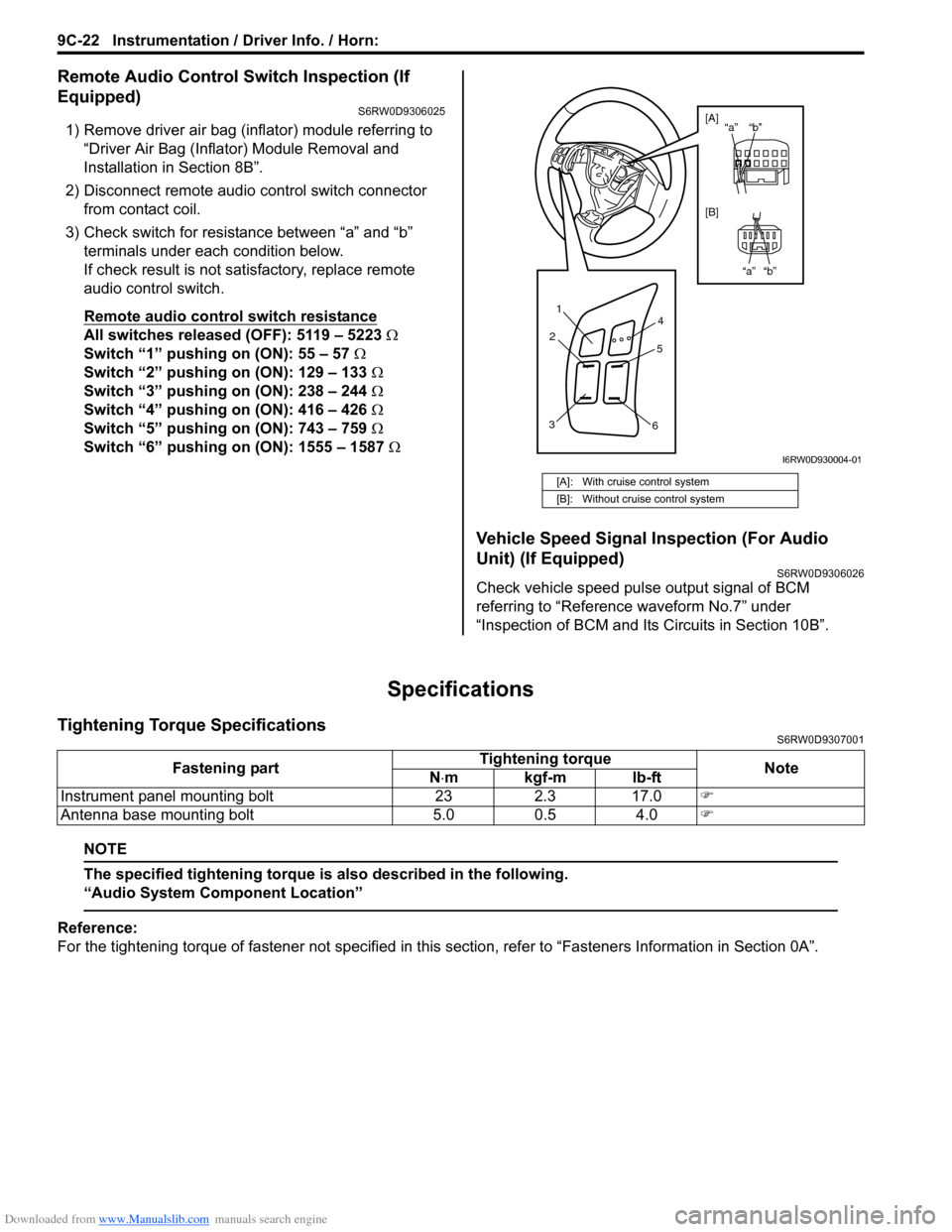
2) Disconnect remote audio control switch connector
from contact coil.
3) Check switch for resistance between “a” and “b”
terminals under each condition below.
If check result is not satisfactory, replace remote
audio control switch.
Remote audio control switch resistance
All switches released (OFF): 5119 – 5223 Ω
Switch “1” pushing on (ON): 55 – 57 Ω
Switch “2” pushing on (ON): 129 – 133 Ω
Switch “3” pushing on (ON): 238 – 244 Ω
Switch “4” pushing on (ON): 416 – 426 Ω
Switch “5” pushing on (ON): 743 – 759 Ω
Switch “6” pushing on (ON): 1555 – 1587 Ω
Vehicle Speed Signal Inspection (For Audio
Unit) (If Equipped)
S6RW0D9306026
Check vehicle speed pulse output signal of BCM
referring to “Reference waveform No.7” under
“Inspection of BCM and Its Circuits in Section 10B”.
Specifications
Tightening Torque SpecificationsS6RW0D9307001
NOTE
The specified tightening torque is also described in the following.
“Audio System Component Location”
Reference:
For the tightening torque of fastener not specified in this section, refer to “Fasteners Information in Section 0A”.
[A]: With cruise control system
[B]: Without cruise control system
1
2
34
5
6
“b” “a”
“b” “a” [A]
[B]
I6RW0D930004-01
Fastening partTightening torque
Note
N⋅mkgf-mlb-ft
Instrument panel mounting bolt 23 2.3 17.0)
Antenna base mounting bolt 5.0 0.5 4.0)