Page 1020 of 1556
Downloaded from www.Manualslib.com manuals search engine 7B-80 Air Conditioning System: Automatic Type
HVAC Unit ComponentsS6RW0D7226002
1
10
1
29
9
8
3
29
21
3
20 20
20
19
23
22
5*
4
28*15 16*
30
29*
30
17*
18*2 1312 11
5*
26
2725
1424
29
67
*
I6RW0C722008-01
1. Blower upper case 9. Air intake control link 17. Expansion valve 25. Inside air temperature sensor
2. Blower lower case 10. Air intake control door 18. Expansion pipe 26. Aspirator
3. Heater unit upper case 11. Blower motor 19.Air flow control actuator 27. Aspirator hose
4. Heater unit lower case 12. Blower motor cap 20. Air flow control links 28. Drain hose
5. Foot duct 13. Blower motor controller 21. Air flow control door assembly 29. Packing
6. HVAC air filter (if equipped) 14. Heater core 22. Temperature control actuator 30. O-ring
: Apply compressor oil.
7. Cover (without HVAC air
filter)15. Evaporator 23. Temperature control link : Do not reuse.
Page 1024 of 1556

Downloaded from www.Manualslib.com manuals search engine 7B-84 Air Conditioning System: Automatic Type
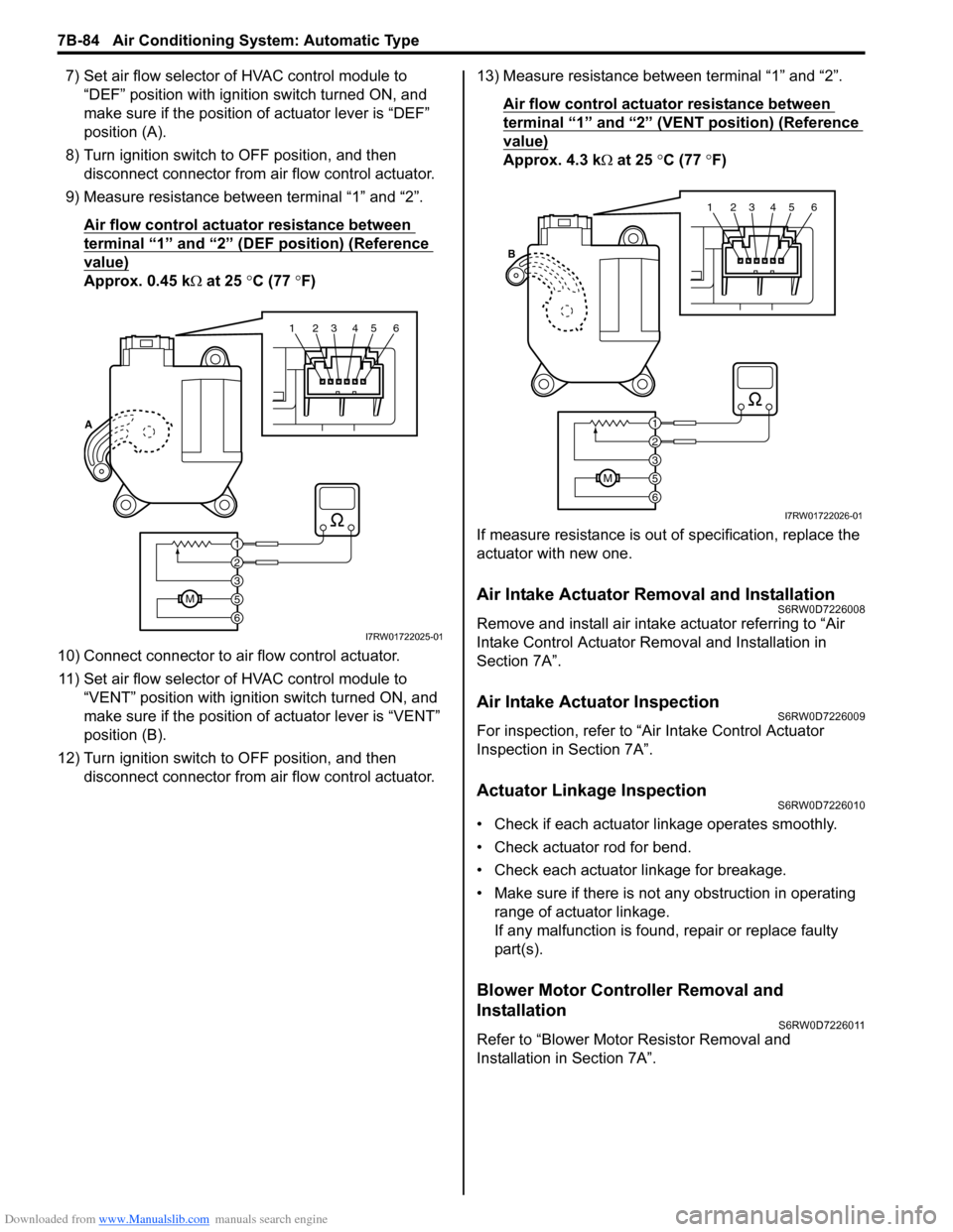
7) Set air flow selector of HVAC control module to
“DEF” position with ignition switch turned ON, and
make sure if the position of actuator lever is “DEF”
position (A).
8) Turn ignition switch to OFF position, and then
disconnect connector from air flow control actuator.
9) Measure resistance between terminal “1” and “2”.
Air flow control actuator resistance between
terminal “1” and “2” (DEF position) (Reference
value)
Approx. 0.45 kΩ at 25 °C (77 °F)
10) Connect connector to air flow control actuator.
11) Set air flow selector of HVAC control module to
“VENT” position with ignition switch turned ON, and
make sure if the position of actuator lever is “VENT”
position (B).
12) Turn ignition switch to OFF position, and then
disconnect connector from air flow control actuator.13) Measure resistance between terminal “1” and “2”.
Air flow control actuator resistance between
terminal “1” and “2” (VENT position) (Reference
value)
Approx. 4.3 kΩ at 25 °C (77 °F)
If measure resistance is out of specification, replace the
actuator with new one.
Air Intake Actuator Removal and InstallationS6RW0D7226008
Remove and install air intake actuator referring to “Air
Intake Control Actuator Removal and Installation in
Section 7A”.
Air Intake Actuator InspectionS6RW0D7226009
For inspection, refer to “Air Intake Control Actuator
Inspection in Section 7A”.
Actuator Linkage InspectionS6RW0D7226010
• Check if each actuator linkage operates smoothly.
• Check actuator rod for bend.
• Check each actuator linkage for breakage.
• Make sure if there is not any obstruction in operating
range of actuator linkage.
If any malfunction is found, repair or replace faulty
part(s).
Blower Motor Controller Removal and
Installation
S6RW0D7226011
Refer to “Blower Motor Resistor Removal and
Installation in Section 7A”.
123456
6
M5
3
2
1 A
I7RW01722025-01
123456
6
M5
3
2
1 B
I7RW01722026-01
Page 1025 of 1556

Downloaded from www.Manualslib.com manuals search engine Air Conditioning System: Automatic Type 7B-85
Blower Motor Controller InspectionS6RW0D7226012
1) Check internal circuit of controller for resistance as
follows.
a) Measure resistance between “1” terminal and “2”
terminal of blower motor controller.
Blower motor controller resistance
“1” – “2”: approximately 10 kΩ
If resistance does not meet above specification,
replace blower motor controller.
b) Using ohmmeter, connect its positive terminal to
“3” terminal of blower motor controller and
negative terminal to “1” terminal of blower motor
controller and check that there is no continuity.
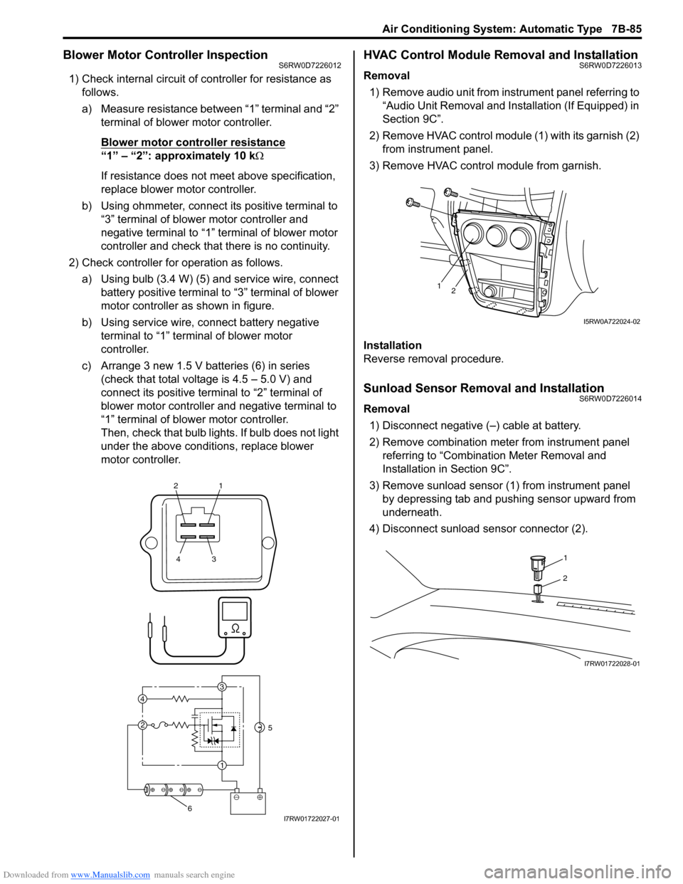
2) Check controller for operation as follows.
a) Using bulb (3.4 W) (5) and service wire, connect
battery positive terminal to “3” terminal of blower
motor controller as shown in figure.
b) Using service wire, connect battery negative
terminal to “1” terminal of blower motor
controller.
c) Arrange 3 new 1.5 V batteries (6) in series
(check that total voltage is 4.5 – 5.0 V) and
connect its positive terminal to “2” terminal of
blower motor controller and negative terminal to
“1” terminal of blower motor controller.
Then, check that bulb lights. If bulb does not light
under the above conditions, replace blower
motor controller.
HVAC Control Module Removal and InstallationS6RW0D7226013
Removal
1) Remove audio unit from instrument panel referring to
“Audio Unit Removal and Installation (If Equipped) in
Section 9C”.
2) Remove HVAC control module (1) with its garnish (2)
from instrument panel.
3) Remove HVAC control module from garnish.
Installation
Reverse removal procedure.
Sunload Sensor Removal and InstallationS6RW0D7226014
Removal
1) Disconnect negative (–) cable at battery.
2) Remove combination meter from instrument panel
referring to “Combination Meter Removal and
Installation in Section 9C”.
3) Remove sunload sensor (1) from instrument panel
by depressing tab and pushing sensor upward from
underneath.
4) Disconnect sunload sensor connector (2).
21
43
3
1 2 4
5
6I7RW01722027-01
12
I5RW0A722024-02
1
2
I7RW01722028-01