2006 SUZUKI SX4 turn signal
[x] Cancel search: turn signalPage 1323 of 1556
Downloaded from www.Manualslib.com manuals search engine Lighting Systems: 9B-4
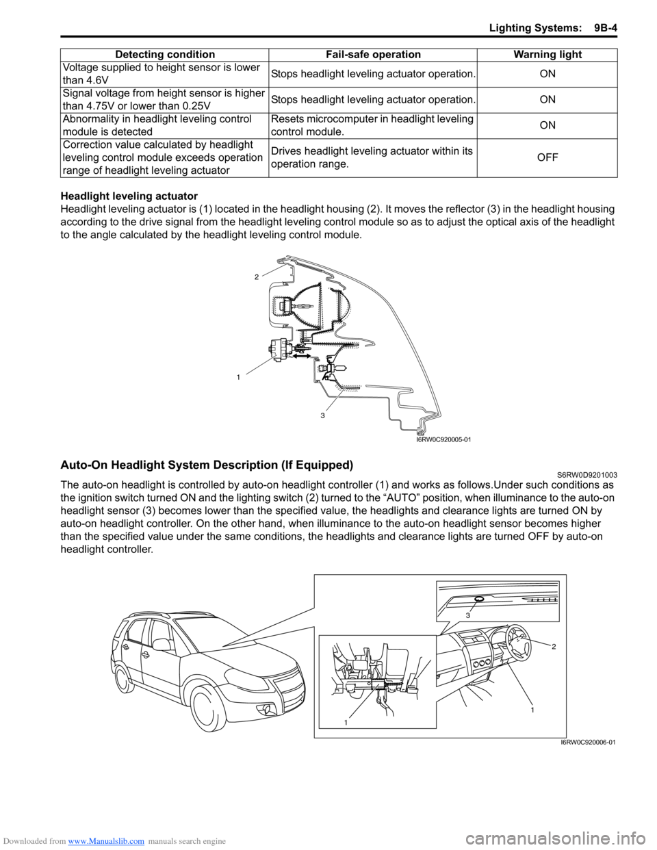
Headlight leveling actuator
Headlight leveling actuator is (1) located in the headlight housing (2). It moves the reflector (3) in the headlight housing
according to the drive signal from the headlight leveling control module so as to adjust the optical axis of the headlight
to the angle calculated by the headlight leveling control module.
Auto-On Headlight System Description (If Equipped)S6RW0D9201003
The auto-on headlight is controlled by auto-on headlight controller (1) and works as follows.Under such conditions as
the ignition switch turned ON and the lighting switch (2) turned to the “AUTO” position, when illuminance to the auto-on
headlight sensor (3) becomes lower than the specified value, the headlights and clearance lights are turned ON by
auto-on headlight controller. On the other hand, when illuminance to the auto-on headlight sensor becomes higher
than the specified value under the same conditions, the headlights and clearance lights are turned OFF by auto-on
headlight controller.Voltage supplied to height sensor is lower
than 4.6VStops headlight leveling actuator operation. ON
Signal voltage from height sensor is higher
than 4.75V or lower than 0.25VStops headlight leveling actuator operation. ON
Abnormality in headlight leveling control
module is detectedResets microcomputer in headlight leveling
control module.ON
Correction value calculated by headlight
leveling control module exceeds operation
range of headlight leveling actuatorDrives headlight leveling actuator within its
operation range.OFF Detecting condition Fail-safe operation Warning light
1
3
2
I6RW0C920005-01
1 3
2
1
I6RW0C920006-01
Page 1326 of 1556
Downloaded from www.Manualslib.com manuals search engine 9B-7 Lighting Systems:
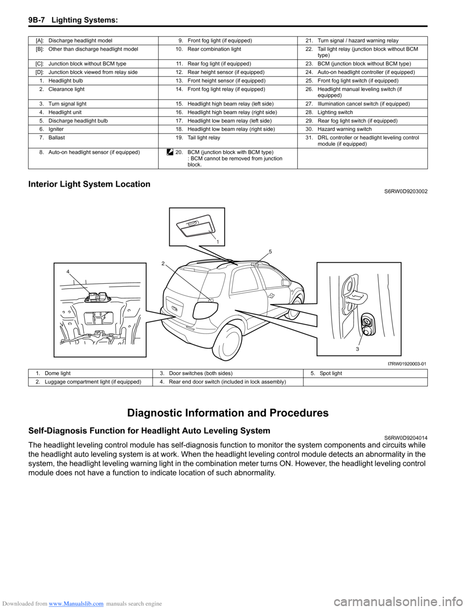
Interior Light System LocationS6RW0D9203002
Diagnostic Information and Procedures
Self-Diagnosis Function for Headlight Auto Leveling SystemS6RW0D9204014
The headlight leveling control module has self-diagnosis function to monitor the system components and circuits while
the headlight auto leveling system is at work. When the headlight leveling control module detects an abnormality in the
system, the headlight leveling warning light in the combination meter turns ON. However, the headlight leveling control
module does not have a function to indicate location of such abnormality.
[A]: Discharge headlight model 9. Front fog light (if equipped) 21. Turn signal / hazard warning relay
[B]: Other than discharge headlight model 10. Rear combination light 22. Tail light relay (junction block without BCM
type)
[C]: Junction block without BCM type 11. Rear fog light (if equipped) 23. BCM (junction block without BCM type)
[D]: Junction block viewed from relay side 12. Rear height sensor (if equipped) 24. Auto-on headlight controller (if equipped)
1. Headlight bulb 13. Front height sensor (if equipped) 25. Front fog light switch (if equipped)
2. Clearance light 14. Front fog light relay (if equipped) 26. Headlight manual leveling switch (if
equipped)
3. Turn signal light 15. Headlight high beam relay (left side) 27. Illumination cancel switch (if equipped)
4. Headlight unit 16. Headlight high beam relay (right side) 28. Lighting switch
5. Discharge headlight bulb 17. Headlight low beam relay (left side) 29. Rear fog light switch (if equipped)
6. Igniter 18. Headlight low beam relay (right side) 30. Hazard warning switch
7. Ballast 19. Tail light relay 31. DRL controller or headlight leveling control
module (if equipped)
8. Auto-on headlight sensor (if equipped) 20. BCM (junction block with BCM type)
: BCM cannot be removed from junction
block.
3 4
5
2
1
I7RW01920003-01
1. Dome light 3. Door switches (both sides) 5. Spot light
2. Luggage compartment light (if equipped) 4. Rear end door switch (included in lock assembly)
Page 1330 of 1556
Downloaded from www.Manualslib.com manuals search engine 9B-11 Lighting Systems:
Turn Signal and Hazard Warning Light Symptom DiagnosisS6RW0D9204004
Clearance, Tail and License Plate Light Symptom DiagnosisS6RW0D9204005
Condition Possible cause Correction / Reference Item
Flash rate high or one
side only flashesBulb blown on “flash rate high”-sideReplace bulb.
Incorrect bulbReplace bulb.
Turn signal / hazard warning relay faultyCheck turn signal / hazard warning relay
referring to “Turn Signal and Hazard Warning
Relay Inspection”.
Open circuit or high resistance existing
either; between turn signal switch and
non lighting bulb, or between hazard
warning switch and non lighting bulbRepair circuit.
Wiring or grounding faultyRepair circuit.
No flashing
NOTE
• Use of SUZUKI scan
tool makes it easy to
check whether a faulty
condition is on the
input side or output
side of BCM. For
checking procedure,
refer to “Diagnosis
Using Output Test
Function of SUZUKI
Scan Tool” under
“Scan Tool Data in
Section 10B”.
• Check each part in the
order from the top of
the following list.
Circuit fuse(s) blownReplace fuse(s) and check for short circuit.
Turn signal / hazard warning relay faultyCheck turn signal / hazard warning relay
referring to “Turn Signal and Hazard Warning
Relay Inspection”.
Turn signal light switch faultyCheck turn signal light switch referring to “Turn
Signal Light Switch (in Lighting Switch)
Inspection”.
Hazard warning switch faultyCheck hazard warning switch referring to
“Hazard Warning Switch Inspection”.
Open circuit or high resistance existing
between battery and switchRepair circuit.
Wiring or grounding faultyRepair circuit.
BCM faultyReplace after making sure that none of above
parts is faulty.
Flash rate lowSupply voltage lowCheck charging system referring to “Generator
Test (Undercharged Battery Check) in Section
1J”.
Turn signal / hazard warning relay faultyCheck turn signal / hazard warning relay
referring to “Turn Signal and Hazard Warning
Relay Inspection”.
Condition Possible cause Correction / Reference Item
All lights do not light upCircuit fuse blownReplace fuse and check for short circuit.
Tail light relay faulty (if equipped)Check tail light relay referring to “Tail Light
Relay, Headlight Relay, Front Fog Light Relay
Inspection (If Equipped)”.
Lighting and dimmer switch faultyCheck lighting and dimmer switch referring to
“Headlight Switch (in Lighting Switch)
Inspection”.
Wiring or grounding faultyRepair circuit.
Some lights do not light
upBulb(s) blownReplace bulb(s).
Wiring or grounding faultyRepair circuit.
Page 1334 of 1556
Downloaded from www.Manualslib.com manuals search engine 9B-15 Lighting Systems:
Auto-On Headlight Operation Inspection (If
Equipped)
S6RW0D9204021
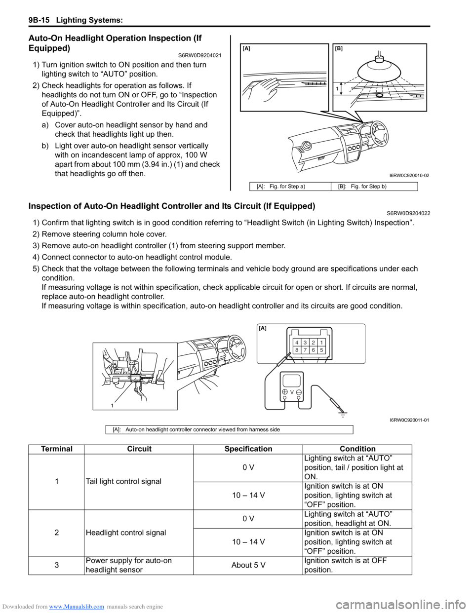
1) Turn ignition switch to ON position and then turn
lighting switch to “AUTO” position.
2) Check headlights for operation as follows. If
headlights do not turn ON or OFF, go to “Inspection
of Auto-On Headlight Controller and Its Circuit (If
Equipped)”.
a) Cover auto-on headlight sensor by hand and
check that headlights light up then.
b) Light over auto-on headlight sensor vertically
with on incandescent lamp of approx, 100 W
apart from about 100 mm (3.94 in.) (1) and check
that headlights go off then.
Inspection of Auto-On Headlight Controller and Its Circuit (If Equipped)S6RW0D9204022
1) Confirm that lighting switch is in good condition referring to “Headlight Switch (in Lighting Switch) Inspection”.
2) Remove steering column hole cover.
3) Remove auto-on headlight controller (1) from steering support member.
4) Connect connector to auto-on headlight control module.
5) Check that the voltage between the following terminals and vehicle body ground are specifications under each
condition.
If measuring voltage is not within specification, check applicable circuit for open or short. If circuits are normal,
replace auto-on headlight controller.
If measuring voltage is within specification, auto-on headlight controller and its circuits are good condition.
[A]: Fig. for Step a) [B]: Fig. for Step b)
[A] [B]
1
I6RW0C920010-02
1
4321
8765
V
[A]
I6RW0C920011-01
[A]: Auto-on headlight controller connector viewed from harness side
Terminal Circuit Specification Condition
1 Tail light control signal0 VLighting switch at “AUTO”
position, tail / position light at
ON.
10 – 14 VIgnition switch is at ON
position, lighting switch at
“OFF” position.
2 Headlight control signal0 VLighting switch at “AUTO”
position, headlight at ON.
10 – 14 VIgnition switch is at ON
position, lighting switch at
“OFF” position.
3Power supply for auto-on
headlight sensorAbout 5 VIgnition switch is at OFF
position.
Page 1336 of 1556
Downloaded from www.Manualslib.com manuals search engine 9B-17 Lighting Systems:
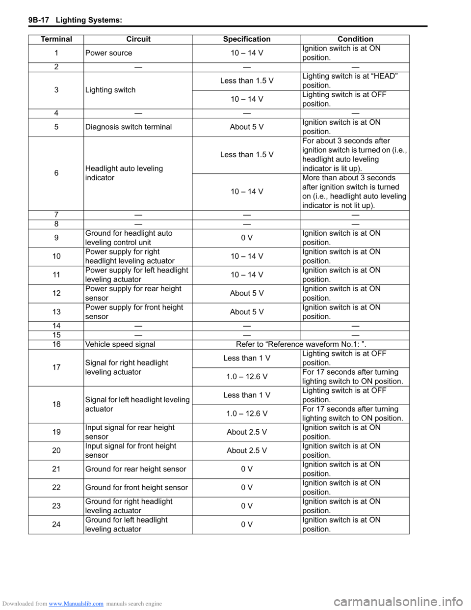
Terminal Circuit Specification Condition
1 Power source 10 – 14 VIgnition switch is at ON
position.
2———
3 Lighting switchLess than 1.5 VLighting switch is at “HEAD”
position.
10 – 14 VLighting switch is at OFF
position.
4———
5 Diagnosis switch terminal About 5 VIgnition switch is at ON
position.
6Headlight auto leveling
indicatorLess than 1.5 VFor about 3 seconds after
ignition switch is turned on (i.e.,
headlight auto leveling
indicator is lit up).
10 – 14 VMore than about 3 seconds
after ignition switch is turned
on (i.e., headlight auto leveling
indicator is not lit up).
7———
8———
9Ground for headlight auto
leveling control unit0 VIgnition switch is at ON
position.
10Power supply for right
headlight leveling actuator10 – 14 VIgnition switch is at ON
position.
11Power supply for left headlight
leveling actuator10 – 14 VIgnition switch is at ON
position.
12Power supply for rear height
sensorAbout 5 VIgnition switch is at ON
position.
13Power supply for front height
sensorAbout 5 VIgnition switch is at ON
position.
14———
15———
16 Vehicle speed signal Refer to “Reference waveform No.1: ”.
17Signal for right headlight
leveling actuatorLess than 1 VLighting switch is at OFF
position.
1.0 – 12.6 VFor 17 seconds after turning
lighting switch to ON position.
18Signal for left headlight leveling
actuatorLess than 1 VLighting switch is at OFF
position.
1.0 – 12.6 VFor 17 seconds after turning
lighting switch to ON position.
19Input signal for rear height
sensorAbout 2.5 VIgnition switch is at ON
position.
20Input signal for front height
sensorAbout 2.5 VIgnition switch is at ON
position.
21 Ground for rear height sensor 0 VIgnition switch is at ON
position.
22 Ground for front height sensor 0 VIgnition switch is at ON
position.
23Ground for right headlight
leveling actuator0 VIgnition switch is at ON
position.
24
Ground for left headlight
leveling actuator0 VIgnition switch is at ON
position.
Page 1343 of 1556
Downloaded from www.Manualslib.com manuals search engine Lighting Systems: 9B-24
Turn Signal Light Switch (in Lighting Switch)
Removal and Installation
S6RW0D9206009
For removal and Installation, refer to “Headlight Switch
(in Lighting Switch) Removal and Installation”.
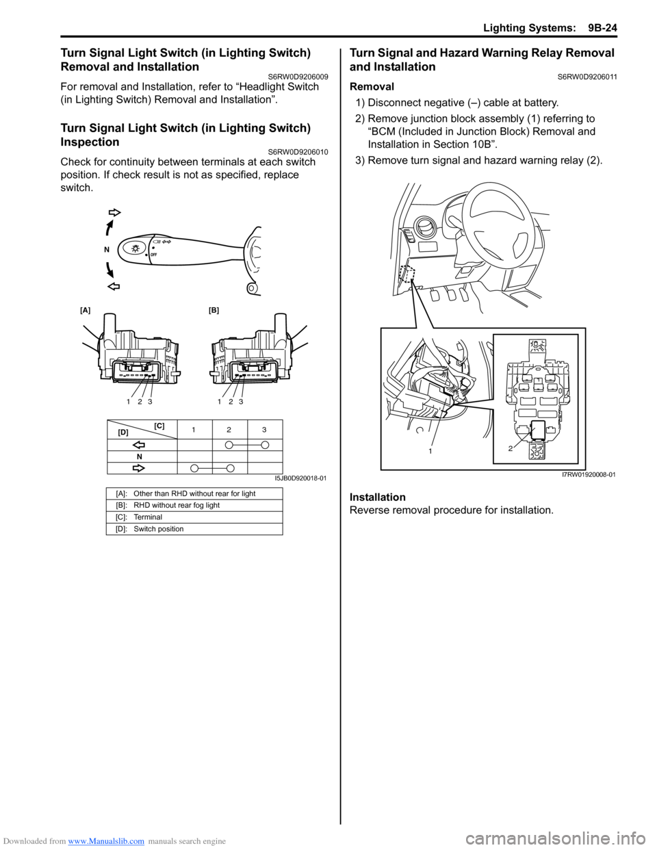
Turn Signal Light Switch (in Lighting Switch)
Inspection
S6RW0D9206010
Check for continuity between terminals at each switch
position. If check result is not as specified, replace
switch.
Turn Signal and Hazard Warning Relay Removal
and Installation
S6RW0D9206011
Removal
1) Disconnect negative (–) cable at battery.
2) Remove junction block assembly (1) referring to
“BCM (Included in Junction Block) Removal and
Installation in Section 10B”.
3) Remove turn signal and hazard warning relay (2).
Installation
Reverse removal procedure for installation.
[A]: Other than RHD without rear for light
[B]: RHD without rear fog light
[C]: Terminal
[D]: Switch position
3 12
3 2 13 2 1
[C]
[D]
[A] [B]
N
N
I5JB0D920018-01
2
1
I7RW01920008-01
Page 1344 of 1556
Downloaded from www.Manualslib.com manuals search engine 9B-25 Lighting Systems:
Turn Signal and Hazard Warning Relay
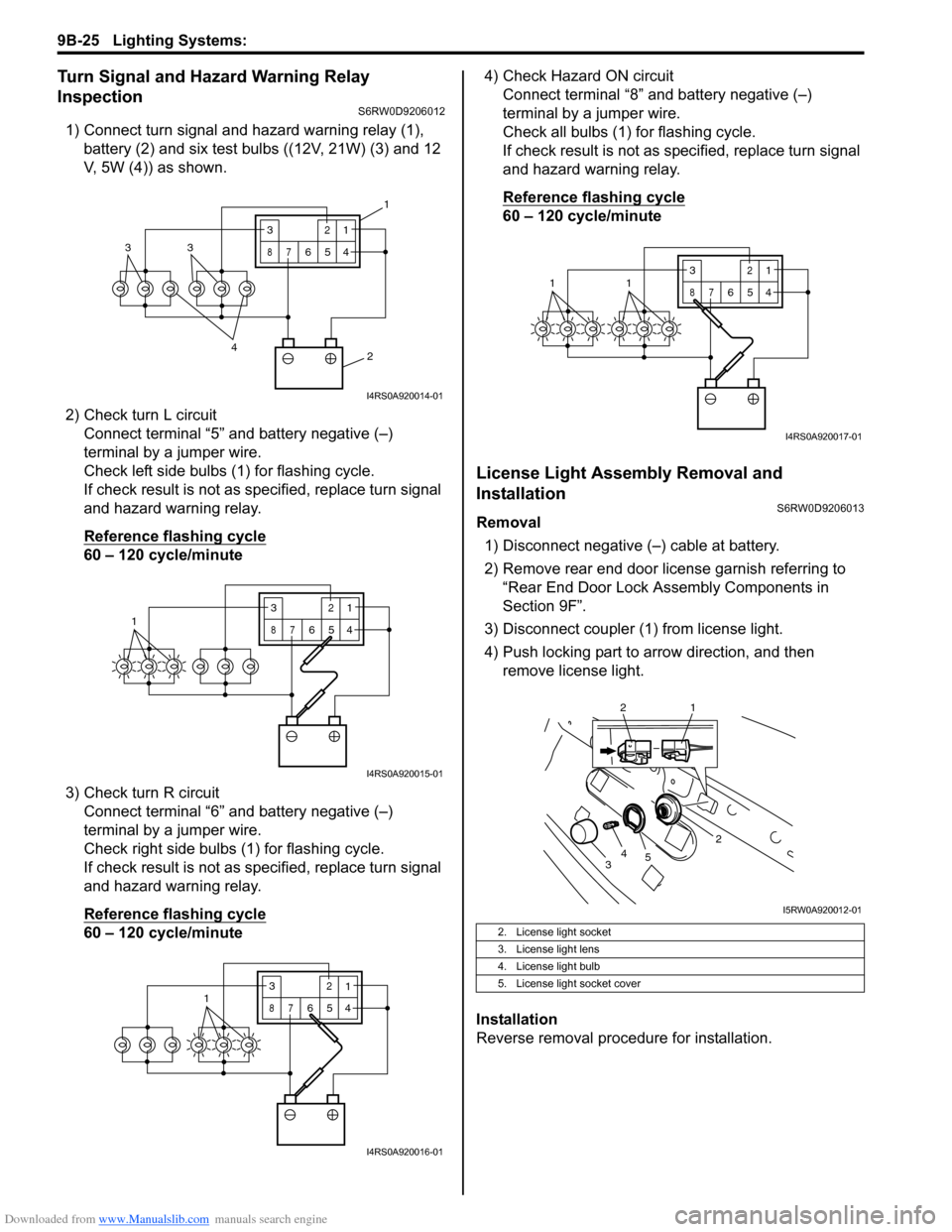
Inspection
S6RW0D9206012
1) Connect turn signal and hazard warning relay (1),
battery (2) and six test bulbs ((12V, 21W) (3) and 12
V, 5W (4)) as shown.
2) Check turn L circuit
Connect terminal “5” and battery negative (–)
terminal by a jumper wire.
Check left side bulbs (1) for flashing cycle.
If check result is not as specified, replace turn signal
and hazard warning relay.
Reference flashing cycle
60 – 120 cycle/minute
3) Check turn R circuit
Connect terminal “6” and battery negative (–)
terminal by a jumper wire.
Check right side bulbs (1) for flashing cycle.
If check result is not as specified, replace turn signal
and hazard warning relay.
Reference flashing cycle
60 – 120 cycle/minute4) Check Hazard ON circuit
Connect terminal “8” and battery negative (–)
terminal by a jumper wire.
Check all bulbs (1) for flashing cycle.
If check result is not as specified, replace turn signal
and hazard warning relay.
Reference flashing cycle
60 – 120 cycle/minute
License Light Assembly Removal and
Installation
S6RW0D9206013
Removal
1) Disconnect negative (–) cable at battery.
2) Remove rear end door license garnish referring to
“Rear End Door Lock Assembly Components in
Section 9F”.
3) Disconnect coupler (1) from license light.
4) Push locking part to arrow direction, and then
remove license light.
Installation
Reverse removal procedure for installation.
2 4
33
3
87
12
654
1
I4RS0A920014-01
13
87
12
654
I4RS0A920015-01
3
87
12
6541
I4RS0A920016-01
2. License light socket
3. License light lens
4. License light bulb
5. License light socket cover
3
87
12
6
5411
I4RS0A920017-01
2
34
5
2 1
I5RW0A920012-01
Page 1353 of 1556
Downloaded from www.Manualslib.com manuals search engine Instrumentation / Driver Info. / Horn: 9C-1
Body, Cab and Accessories
Instrumentation / Driver Info. / Horn
Precautions
Precautions in Diagnosing Troubles for Combination MeterS6RW0D9300001
Combination meter uses signals (information) from each control module by CAN communication to control
speedometer, tachometer, fuel meter, engine coolant temp meter, warning light and indicator light (other than air bag
warning light, EPS warning light, headlight leveling warning light (if equipped), rear fog light indicator light (if
equipped), high beam indicator light and turn signal indicator light). Therefor, check that no DTC is detected in each
module before performing combination meter symptom diagnosis. If any DTC is detected, correct trouble indicated by
that DTC troubleshooting first.
General Description
CAN Communication System DescriptionS6RW0D9301001
Refer to “CAN Communication System Description in Section 1A” for CAN communication system description.
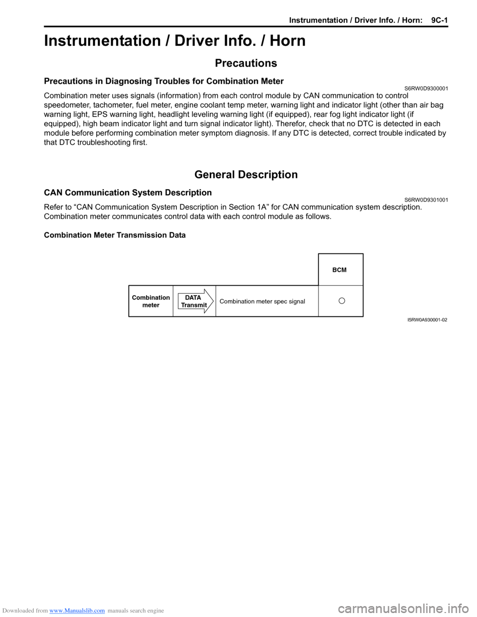
Combination meter communicates control data with each control module as follows.
Combination Meter Transmission Data
BCM
Combination
meterDATA
TransmitCombination meter spec signal
I5RW0A930001-02