2006 SUZUKI SX4 Drive shaft
[x] Cancel search: Drive shaftPage 842 of 1556
Downloaded from www.Manualslib.com manuals search engine 5B-30 Manual Transmission/Transaxle:
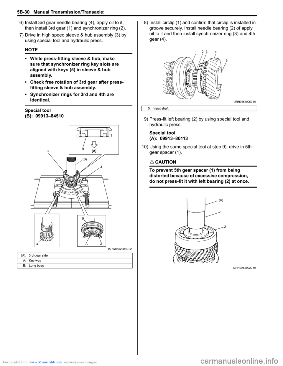
6) Install 3rd gear needle bearing (4), apply oil to it,
then install 3rd gear (1) and synchronizer ring (2).
7) Drive in high speed sleeve & hub assembly (3) by
using special tool and hydraulic press.
NOTE
• While press-fitting sleeve & hub, make
sure that synchronizer ring key slots are
aligned with keys (5) in sleeve & hub
assembly.
• Check free rotation of 3rd gear after press-
fitting sleeve & hub assembly.
• Synchronizer rings for 3rd and 4th are
identical.
Special tool
(B): 09913–845108) Install circlip (1) and confirm that circlip is installed in
groove securely. Install needle bearing (2) of apply
oil to it and then install synchronizer ring (3) and 4th
gear (4).
9) Press-fit left bearing (2) by using special tool and
hydraulic press.
Special tool
(A): 09913–80113
10) Using the same special tool at step 9), drive in 5th
gear spacer (1).
CAUTION!
To prevent 5th gear spacer (1) from being
distorted because of excessive compression,
do not press-fit it with left bearing (2) at once.
[A]: 3rd gear side
A: Key way
B: Long boss
B
[A]3
(B)
4A 5
21
I5RW0A520034-02
5. Input shaft
I2RH01520052-01
I3RH0A520020-01
Page 843 of 1556

Downloaded from www.Manualslib.com manuals search engine Manual Transmission/Transaxle: 5B-31
Countershaft Disassembly and ReassemblyS6RW0D5206021
Disassembly
1) Drive out left bearing cone (2) with 4th gear (3) by
using puller (4) and hydraulic press.
CAUTION!
• Use puller and hydraulic press that will
bear at least 5 ton (11,000 lb) safely.
• To avoid tooth damage, support 4th gear
(3) at flat side of puller.
2) Apply puller (5) to 2nd gear (4) and drive out 3rd &
4th gear spacer (2) and 3rd gear (3) together with
2nd gear by using hydraulic press. Needle bearing
would come out with 2nd gear.
CAUTION!
• If compression exceeds 5 ton (11,000 lb),
release compression once, reset bearing
puller and then continue press work again.
• To avoid gear tooth from being damaged,
support it at flat side of bearing puller.
3) Take out 2nd synchronizer outer ring, center cone
and inner ring.
4) Using special tool, remove circlip (1).
NOTE
Correct tool tips to be flat to facilitate
removal of circlip.
Special tool
(A): 09900–06107
5) Apply puller (3) to 1st gear (2) and drive out low
speed synchronizer sleeve & hub assembly (1) with
1st gear by using hydraulic press.
CAUTION!
To avoid gear tooth from damage, support it
at flat side of bearing puller.
1. Countershaft
1. Countershaft
I2RH01520054-01
I2RH01520055-01
2. Low speed synchronizer sleeve
I2RH01520056-01
I2RH01520057-01
Page 845 of 1556
Downloaded from www.Manualslib.com manuals search engine Manual Transmission/Transaxle: 5B-33
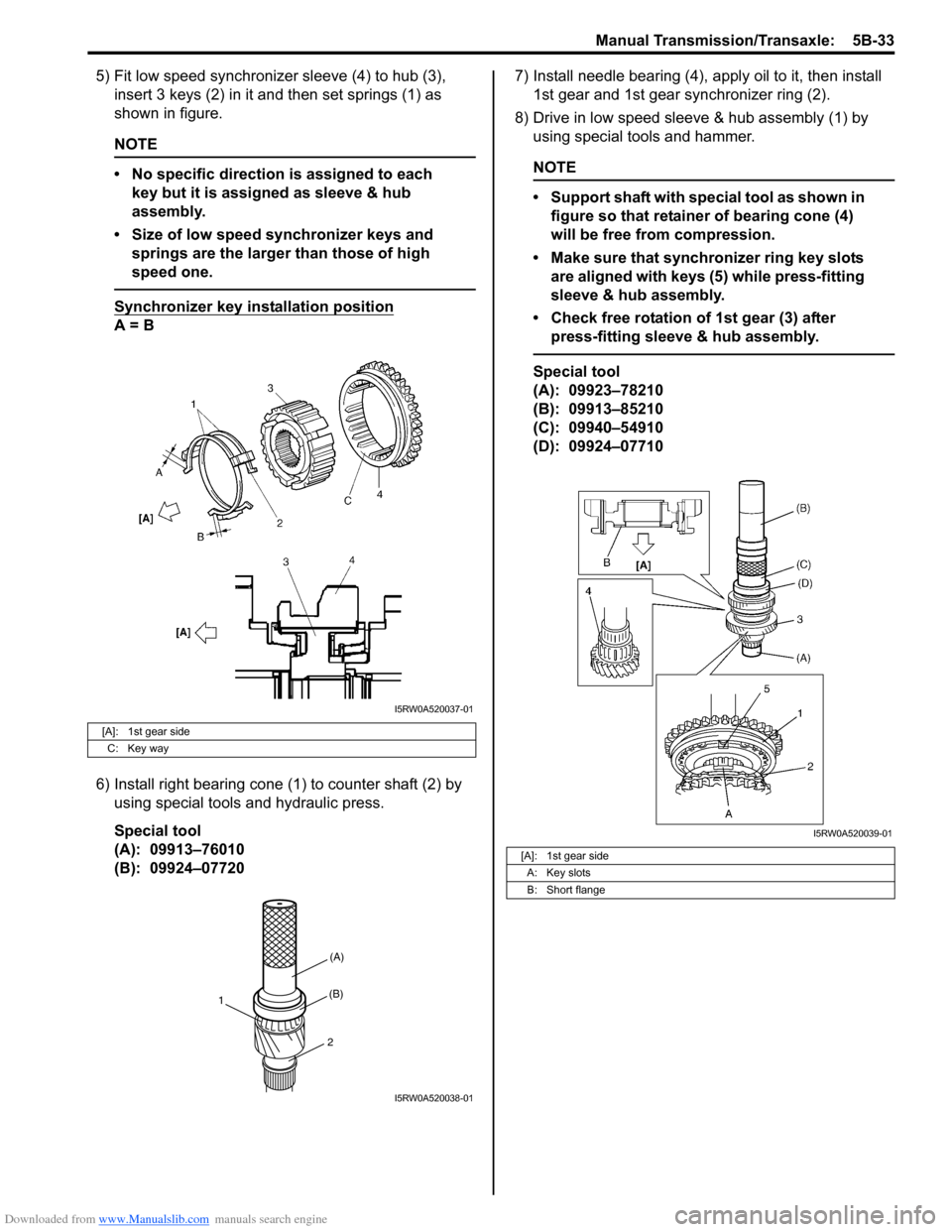
5) Fit low speed synchronizer sleeve (4) to hub (3),
insert 3 keys (2) in it and then set springs (1) as
shown in figure.
NOTE
• No specific direction is assigned to each
key but it is assigned as sleeve & hub
assembly.
• Size of low speed synchronizer keys and
springs are the larger than those of high
speed one.
Synchronizer key installation position
A = B
6) Install right bearing cone (1) to counter shaft (2) by
using special tools and hydraulic press.
Special tool
(A): 09913–76010
(B): 09924–077207) Install needle bearing (4), apply oil to it, then install
1st gear and 1st gear synchronizer ring (2).
8) Drive in low speed sleeve & hub assembly (1) by
using special tools and hammer.
NOTE
• Support shaft with special tool as shown in
figure so that retainer of bearing cone (4)
will be free from compression.
• Make sure that synchronizer ring key slots
are aligned with keys (5) while press-fitting
sleeve & hub assembly.
• Check free rotation of 1st gear (3) after
press-fitting sleeve & hub assembly.
Special tool
(A): 09923–78210
(B): 09913–85210
(C): 09940–54910
(D): 09924–07710
[A]: 1st gear side
C: Key way
I5RW0A520037-01
(A)
(B)
2
1
I5RW0A520038-01
[A]: 1st gear side
A: Key slots
B: Short flange
I5RW0A520039-01
Page 849 of 1556
Downloaded from www.Manualslib.com manuals search engine Manual Transmission/Transaxle: 5B-37
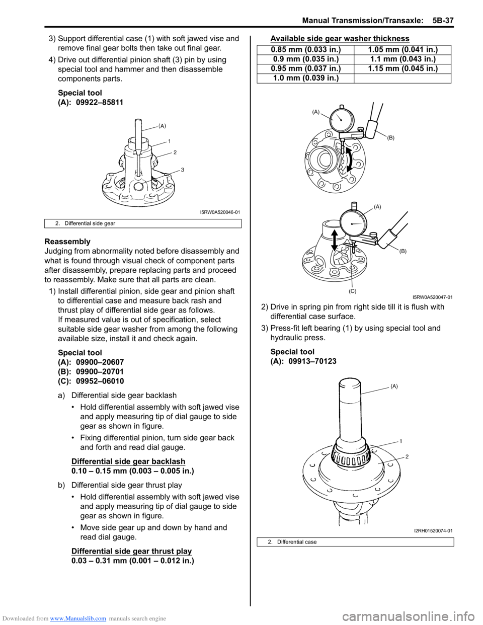
3) Support differential case (1) with soft jawed vise and
remove final gear bolts then take out final gear.
4) Drive out differential pinion shaft (3) pin by using
special tool and hammer and then disassemble
components parts.
Special tool
(A): 09922–85811
Reassembly
Judging from abnormality noted before disassembly and
what is found through visual check of component parts
after disassembly, prepare replacing parts and proceed
to reassembly. Make sure that all parts are clean.
1) Install differential pinion, side gear and pinion shaft
to differential case and measure back rash and
thrust play of differential side gear as follows.
If measured value is out of specification, select
suitable side gear washer from among the following
available size, install it and check again.
Special tool
(A): 09900–20607
(B): 09900–20701
(C): 09952–06010
a) Differential side gear backlash
• Hold differential assembly with soft jawed vise
and apply measuring tip of dial gauge to side
gear as shown in figure.
• Fixing differential pinion, turn side gear back
and forth and read dial gauge.
Differential side gear backlash
0.10 – 0.15 mm (0.003 – 0.005 in.)
b) Differential side gear thrust play
• Hold differential assembly with soft jawed vise
and apply measuring tip of dial gauge to side
gear as shown in figure.
• Move side gear up and down by hand and
read dial gauge.
Differential side gear thrust play
0.03 – 0.31 mm (0.001 – 0.012 in.)Available side gear washer thickness
2) Drive in spring pin from right side till it is flush with
differential case surface.
3) Press-fit left bearing (1) by using special tool and
hydraulic press.
Special tool
(A): 09913–70123
2. Differential side gear
I5RW0A520046-01
0.85 mm (0.033 in.) 1.05 mm (0.041 in.)
0.9 mm (0.035 in.) 1.1 mm (0.043 in.)
0.95 mm (0.037 in.) 1.15 mm (0.045 in.)
1.0 mm (0.039 in.)
2. Differential case
(B)
(B)
(C)
(A)
(A)
I5RW0A520047-01
I2RH01520074-01
Page 854 of 1556

Downloaded from www.Manualslib.com manuals search engine 5C-1 Clutch:
Transmission / Transaxle
Clutch
General Description
Clutch (Hydraulic Type) ConstructionS6RW0D5301001
The clutch is a diaphragm spring clutch of a dry single disc type. The diaphragm spring is of a tapering-finger type,
which is a solid ring in the outer diameter part, with a series of tapered fingers pointing inward.
The disc, carrying four torsional coil springs, is positioned on the transaxle input shaft with an involute spline fit.
The clutch cover is secured to the flywheel, and carries the diaphragm spring in such a way that the peripheral edge
part of the spring pushes on the pressure plate against the flywheel (with the disc in between), when the clutch release
bearing (incorporated in clutch operating cylinder) is held back. This is the engaged condition of the clutch.
Depressing the clutch pedal causes the release bearing (incorporated in clutch operating cylinder) to advance and
pushes on the tips of the tapered fingers of the diaphragm spring. When this happens, the diaphragm spring pulls the
pressure plate away from the flywheel, thereby interrupting the flow of drive from flywheel through clutch disc to
transaxle input shaft. Clutch fluid is supplied from brake fluid reservoir. Clutch fluid level can be checked by brake fluid
level of brake fluid reservoir.
I5RW0A530001-01
1. Crankshaft 4. Pressure plate 7. Operating cylinder assembly
2. Flywheel 5. Clutch cover 8. Input shaft bearing
3. Clutch disc 6. Diaphragm spring 9. Input shaft
Page 863 of 1556

Downloaded from www.Manualslib.com manuals search engine Clutch: 5C-10
Special Tools and Equipment
Recommended Service MaterialS6RW0D5308001
Special ToolS6RW0D5308002
Material SUZUKI recommended product or Specification Note
Grease SUZUKI Silicone Grease P/No.: 99000–25100)
SUZUKI Super Grease I P/No.: 99000–25210)
09921–26020 09923–36320
Bearing remover Clutch center guide (15 mm)
))
09924–17810 09924–17811
Flywheel holder (drive plate
stopper)Flywheel holder
) / )) / )
09925–98210 09930–30104
Input shaft bearing installer Sliding shaft
))
Page 870 of 1556

Downloaded from www.Manualslib.com manuals search engine 6B-1 Steering Wheel and Column:
Ste eri ng
Steering Wheel and Column
Precautions
Service Precautions of Steering Wheel and ColumnS6RW0D6200001
For service precautions, refer to “Precautions on Service and Diagnosis of Air Bag System in Section 8B”.
Service and Diagnosis
For diagnosis and servicing, refer to “Precautions on Service and Diagnosis of Air Bag System in Section 8B”.
Disabling Air Bag System
For disabling air bag system, refer to “Disabling Air Bag System in Section 8B”.
Enabling Air Bag System
For enabling air bag system, refer to “Enabling Air Bag System in Section 8B”.
Handling and Storage
For handling and storage, refer to “Precautions on Handling and Storage of Air Bag System Components in Section
8B”.
Disposal
For disposal, refer to “Precautions on Disposal of Air Bag and Seat Belt Pretensioner in Section 8B”.
General Description
Steering Wheel and Column ConstructionS6RW0D6201001
This double tube type steering column has the following three important features in addition to the steering function:
• The column is energy absorbing, designed to compress in a front-end collision.
• The ignition switch and lock are mounted conveniently on this column.
• With the column mounted lock, the ignition and steering operations can be locked to inhibit theft of the vehicle.
To insure the energy absorbing action, it is important that only the specified screws, bolts and nuts be used as
designated, and that they are tightened to the specified torque. When the column assembly is removed from the
vehicle, special care must be taken in handling it. Use of a steering wheel puller other than the recommended puller in
this manual or a sharp blow on the end of the steering shaft, leaning on the assembly, or dropping the assembly could
shear the plastic shear pins which maintain column length and position.
The driver air bag (inflator) module is one of the supplemental restraint (air bag) system components and is mounted
to the center of the steering wheel. During certain frontal crashes, the air bag system supplements the restraint of the
driver’s and passenger’s seat belts by deploying the air bags. The air bag (inflator) module should be handled with
care to prevent accidental deployment. When servicing, be sure to observe “Precautions on Service and Diagnosis of
Air Bag System in Section 8B”.
Page 873 of 1556

Downloaded from www.Manualslib.com manuals search engine Steering Wheel and Column: 6B-4
Steering Wheel Removal and InstallationS6RW0D6206002
CAUTION!
Do not turn the contact coil more than
allowable number of turns (about two and a
half turns from the center position clockwise
or counterclockwise respectively) with
steering wheel removed, or coil will break.
Removal
CAUTION!
Do not hammer the end of the shaft.
Hammering it will loosen the plastic shear
pins which maintain the column length and
impair the collapsible design of the column.
1) Disconnect negative (–) cable at battery.
2) Disable air bag system referring to “Disabling Air
Bag System in Section 8B”.
3) Remove driver air bag (inflator) module from
steering wheel. Refer to “Driver Air Bag (Inflator)
Module Removal and Installation in Section 8B”.
4) Disconnect horn connector and audio control switch
connector, if equipped.
5) Remove steering shaft nut and then make alignment
marks (1) on steering wheel and shaft for a guide
during reinstallation.6) Remove steering wheel using special tool.
Special tool
(A): 09944–36011
InstallationCAUTION!
Following 2 Steps (Step 1) and 2)) are
prerequisite for installation of steering wheel.
If steering wheel has been installed without
these 2 Steps, contact coil will break when
steering wheel is turned.
1) Check that vehicle’s front tires are at straight-ahead
position and contact coil is centered. If contact coil is
turned after removing steering wheel, center contact
coil referring to “Centering Contact Coil Cable
Assembly”.
2) Install steering wheel to steering shaft with 2 grooves
(1) on contact coil fitted in 2 lugs (2) in the back of
steering wheel and also aligning marks (3) on
steering wheel and steering shaft.
3) Tighten steering shaft nut (4) to specified torque.
Tightening torque
Steering shaft nut (a): 33 N·m (3.3 kgf-m, 24.0 lb-
ft)
I4RS0A620005-01
(A)
I4RS0A620006-01
I4RS0A620007-01