2006 SUZUKI SX4 Ac panel
[x] Cancel search: Ac panelPage 1493 of 1556
Downloaded from www.Manualslib.com manuals search engine Body Electrical Control System: 10B-20
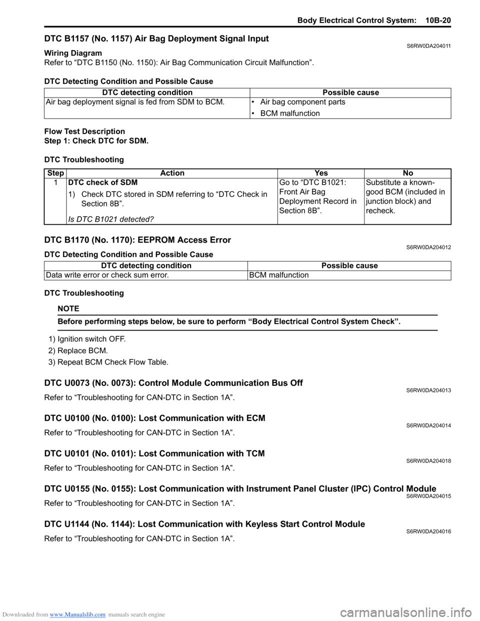
DTC B1157 (No. 1157) Air Bag Deployment Signal InputS6RW0DA204011
Wiring Diagram
Refer to “DTC B1150 (No. 1150): Air Bag Communication Circuit Malfunction”.
DTC Detecting Condition and Possible Cause
Flow Test Description
Step 1: Check DTC for SDM.
DTC Troubleshooting
DTC B1170 (No. 1170): EEPROM Access ErrorS6RW0DA204012
DTC Detecting Condition and Possible Cause
DTC Troubleshooting
NOTE
Before performing steps below, be sure to perform “Body Electrical Control System Check”.
1) Ignition switch OFF.
2) Replace BCM.
3) Repeat BCM Check Flow Table.
DTC U0073 (No. 0073): Control Module Communication Bus OffS6RW0DA204013
Refer to “Troubleshooting for CAN-DTC in Section 1A”.
DTC U0100 (No. 0100): Lost Communication with ECMS6RW0DA204014
Refer to “Troubleshooting for CAN-DTC in Section 1A”.
DTC U0101 (No. 0101): Lost Communication with TCMS6RW0DA204018
Refer to “Troubleshooting for CAN-DTC in Section 1A”.
DTC U0155 (No. 0155): Lost Communication with Instrument Panel Cluster (IPC) Control ModuleS6RW0DA204015
Refer to “Troubleshooting for CAN-DTC in Section 1A”.
DTC U1144 (No. 1144): Lost Communication with Keyless Start Control ModuleS6RW0DA204016
Refer to “Troubleshooting for CAN-DTC in Section 1A”. DTC detecting condition Possible cause
Air bag deployment signal is fed from SDM to BCM. • Air bag component parts
• BCM malfunction
Step Action Yes No
1DTC check of SDM
1) Check DTC stored in SDM referring to “DTC Check in
Section 8B”.
Is DTC B1021 detected?Go to “DTC B1021:
Front Air Bag
Deployment Record in
Section 8B”.Substitute a known-
good BCM (included in
junction block) and
recheck.
DTC detecting condition Possible cause
Data write error or check sum error. BCM malfunction
Page 1508 of 1556
Downloaded from www.Manualslib.com manuals search engine 10C-6 Immobilizer Control System:
DTC CheckS6RW0DA304002
NOTE
To know how to use SUZUKI scan tool in
detail, refer to its operator’s manual.
1) Turn the ignition switch to OFF position.
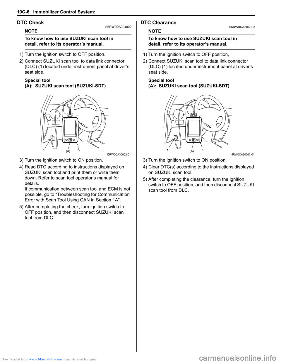
2) Connect SUZUKI scan tool to data link connector
(DLC) (1) located under instrument panel at driver’s
seat side.
Special tool
(A): SUZUKI scan tool (SUZUKI-SDT)
3) Turn the ignition switch to ON position.
4) Read DTC according to instructions displayed on
SUZUKI scan tool and print them or write them
down. Refer to scan tool operator’s manual for
details.
If communication between scan tool and ECM is not
possible, go to “Troubleshooting for Communication
Error with Scan Tool Using CAN in Section 1A”.
5) After completing the check, turn ignition switch to
OFF position, and then disconnect SUZUKI scan
tool from DLC.
DTC ClearanceS6RW0DA304003
NOTE
To know how to use SUZUKI scan tool in
detail, refer to its operator’s manual.
1) Turn the ignition switch to OFF position,
2) Connect SUZUKI scan tool to data link connector
(DLC) (1) located under instrument panel at driver’s
seat side.
Special tool
(A): SUZUKI scan tool (SUZUKI-SDT)
3) Turn the ignition switch to ON position.
4) Clear DTC(s) according to the instructions displayed
on SUZUKI scan tool.
5) After completing the clearance, turn the ignition
switch to OFF position, and then disconnect SUZUKI
scan tool from DLC.
(A) 1I5RW0CA30002-01(A) 1I5RW0CA30002-01
Page 1527 of 1556
Downloaded from www.Manualslib.com manuals search engine Keyless Start System: 10E-5
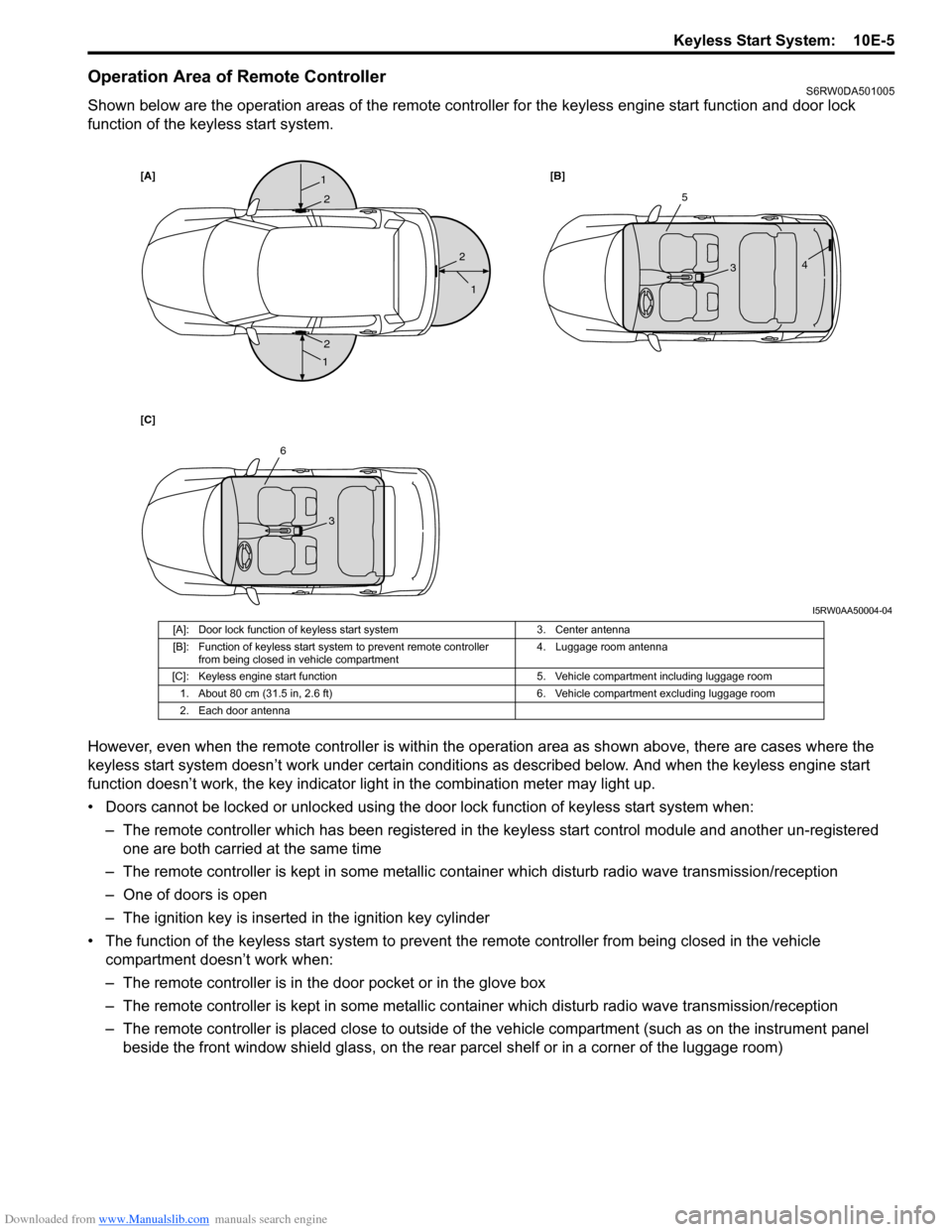
Operation Area of Remote ControllerS6RW0DA501005
Shown below are the operation areas of the remote controller for the keyless engine start function and door lock
function of the keyless start system.
However, even when the remote controller is within the operation area as shown above, there are cases where the
keyless start system doesn’t work under certain conditions as described below. And when the keyless engine start
function doesn’t work, the key indicator light in the combination meter may light up.
• Doors cannot be locked or unlocked using the door lock function of keyless start system when:
– The remote controller which has been registered in the keyless start control module and another un-registered
one are both carried at the same time
– The remote controller is kept in some metallic container which disturb radio wave transmission/reception
– One of doors is open
– The ignition key is inserted in the ignition key cylinder
• The function of the keyless start system to prevent the remote controller from being closed in the vehicle
compartment doesn’t work when:
– The remote controller is in the door pocket or in the glove box
– The remote controller is kept in some metallic container which disturb radio wave transmission/reception
– The remote controller is placed close to outside of the vehicle compartment (such as on the instrument panel
beside the front window shield glass, on the rear parcel shelf or in a corner of the luggage room)
[A][B]
[C]1
1
1
2
2
25
34
6
3
I5RW0AA50004-04
[A]: Door lock function of keyless start system 3. Center antenna
[B]: Function of keyless start system to prevent remote controller
from being closed in vehicle compartment4. Luggage room antenna
[C]: Keyless engine start function 5. Vehicle compartment including luggage room
1. About 80 cm (31.5 in, 2.6 ft) 6. Vehicle compartment excluding luggage room
2. Each door antenna
Page 1528 of 1556
Downloaded from www.Manualslib.com manuals search engine 10E-6 Keyless Start System:
• The ignition knob switch cannot be turned using the keyless engine start function fails to turn:
– The remote controller which has been registered in the keyless start control module and another un-registered
one are both carried at the same time
– The remote controller is kept in some metallic container which disturbs radio wave transmission/reception
– The ignition knob switch has been pushed for 5 seconds or longer
– The remote controller is placed close to outside of the vehicle compartment (such as on the instrument panel
beside the front window shield glass, on the rear parcel shelf or in a corner of the luggage room)
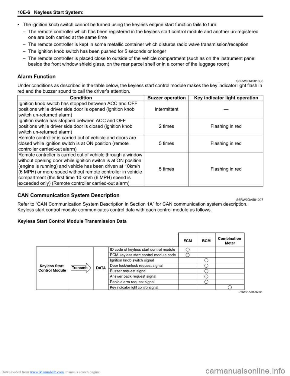
Alarm FunctionS6RW0DA501006
Under conditions as described in the table below, the keyless start control module makes the key indicator light flash in
red and the buzzer sound to call the driver’s attention.
CAN Communication System DescriptionS6RW0DA501007
Refer to “CAN Communication System Description in Section 1A” for CAN communication system description.
Keyless start control module communicates control data with each control module as follows.
Keyless Start Control Module Transmission DataCondition Buzzer operation Key indicator light operation
Ignition knob switch has stopped between ACC and OFF
positions while driver side door is opened (ignition knob
switch un-returned alarm)Intermittent —
Ignition switch has stopped between ACC and OFF
positions while driver side door is closed (ignition knob
switch un-returned alarm)2 times Flashing in red
Remote controller is carried out of vehicle and doors are
closed while ignition switch is at ON position (remote
controller carried-out alarm)5 times Flashing in red
Remote controller is carried out of vehicle through a window
without opening door while ignition switch is at ON position
(engine is running) and vehicle has been driven at 10km/h
(6 MPH) or more speed without remote controller in vehicle
compartment (the first time 10 km/h (6 MPH) speed is
exceeded only) (Remote controller carried-out alarm)5 times Flashing in red
BCM ECMCombination
Meter
ID code of keyless start control modulee
ECM-keyless start control module codeke
Ignition knob switch signal
Door lock/unlock request signal
Buzzer request signal
Answer back request signal
Panic alarm request signal
Key indicator light control signal DATA Transmit
Keyless Start
Control Module
I7RW01A50002-01
Page 1550 of 1556
Downloaded from www.Manualslib.com manuals search engine 10E-28 Keyless Start System:
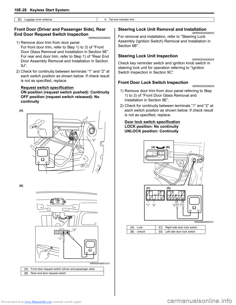
Front Door (Driver and Passenger Side), Rear
End Door Request Switch Inspection
S6RW0DA506002
1) Remove door trim from door panel.
For front door trim, refer to Step 1) to 3) of “Front
Door Glass Removal and Installation in Section 9E”.
For rear end door trim, refer to Step 1) of “Rear End
Door Assembly Removal and Installation in Section
9J”.
2) Check for continuity between terminals “1” and “2” at
each switch position as shown below. If check result
is not as specified, replace.
Request switch specification
ON position (request switch pushed): Continuity
OFF position (request switch released): No
continuity
Steering Lock Unit Removal and InstallationS6RW0DA506003
For removal and installation, refer to “Steering Lock
Assembly (Ignition Switch) Removal and Installation in
Section 6B”.
Steering Lock Unit InspectionS6RW0DA506004
Check key reminder switch and ignition knob switch in
steering lock unit for operation referring to “Ignition
Switch Inspection in Section 9C”.
Front Door Lock Switch InspectionS6RW0DA506005
1) Remove door trim from door panel referring to Step
1) to 3) of “Front Door Glass Removal and
Installation in Section 9E”.
2) Check for continuity between terminals “1” and “2” at
each switch position as shown below. If check result
is not as specified, replace.
Door lock switch specification
LOCK position: No continuity
UNLOCK position: Continuity
[E]: Luggage room antenna 5. Tail end member trim
[A]: Front door request switch (driver and passenger side)
[B]: Rear end door request switch
[A]
2
[B]
2
1
1
I5RW0AA50015-01
[A]: Lock [C]: Right side door lock switch
[B]: Unlock [D]: Left side door lock switch
[C] [D]
[A] [B]
1212
I4RS0BA50029-01
Page 1551 of 1556
Downloaded from www.Manualslib.com manuals search engine Keyless Start System: 10E-29
Keyless Start Control Module Removal and
Installation
S6RW0DA506006
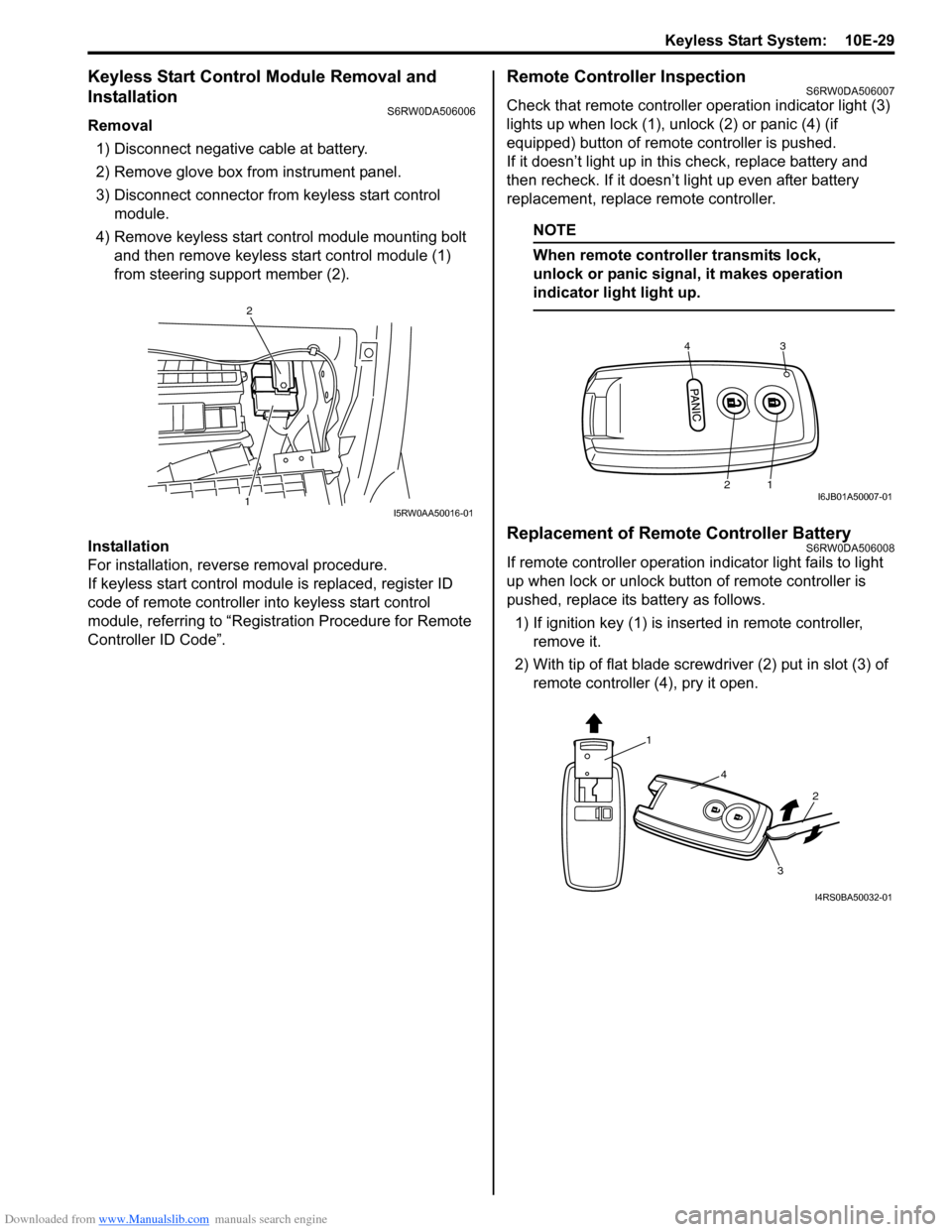
Removal
1) Disconnect negative cable at battery.
2) Remove glove box from instrument panel.
3) Disconnect connector from keyless start control
module.
4) Remove keyless start control module mounting bolt
and then remove keyless start control module (1)
from steering support member (2).
Installation
For installation, reverse removal procedure.
If keyless start control module is replaced, register ID
code of remote controller into keyless start control
module, referring to “Registration Procedure for Remote
Controller ID Code”.
Remote Controller InspectionS6RW0DA506007
Check that remote controller operation indicator light (3)
lights up when lock (1), unlock (2) or panic (4) (if
equipped) button of remote controller is pushed.
If it doesn’t light up in this check, replace battery and
then recheck. If it doesn’t light up even after battery
replacement, replace remote controller.
NOTE
When remote controller transmits lock,
unlock or panic signal, it makes operation
indicator light light up.
Replacement of Remote Controller BatteryS6RW0DA506008
If remote controller operation indicator light fails to light
up when lock or unlock button of remote controller is
pushed, replace its battery as follows.
1) If ignition key (1) is inserted in remote controller,
remove it.
2) With tip of flat blade screwdriver (2) put in slot (3) of
remote controller (4), pry it open.
1
2
I5RW0AA50016-01
43
21I6JB01A50007-01
1
4
2
3
I4RS0BA50032-01