Page 1394 of 1556
Downloaded from www.Manualslib.com manuals search engine 9E-9 Glass / Windows / Mirrors:
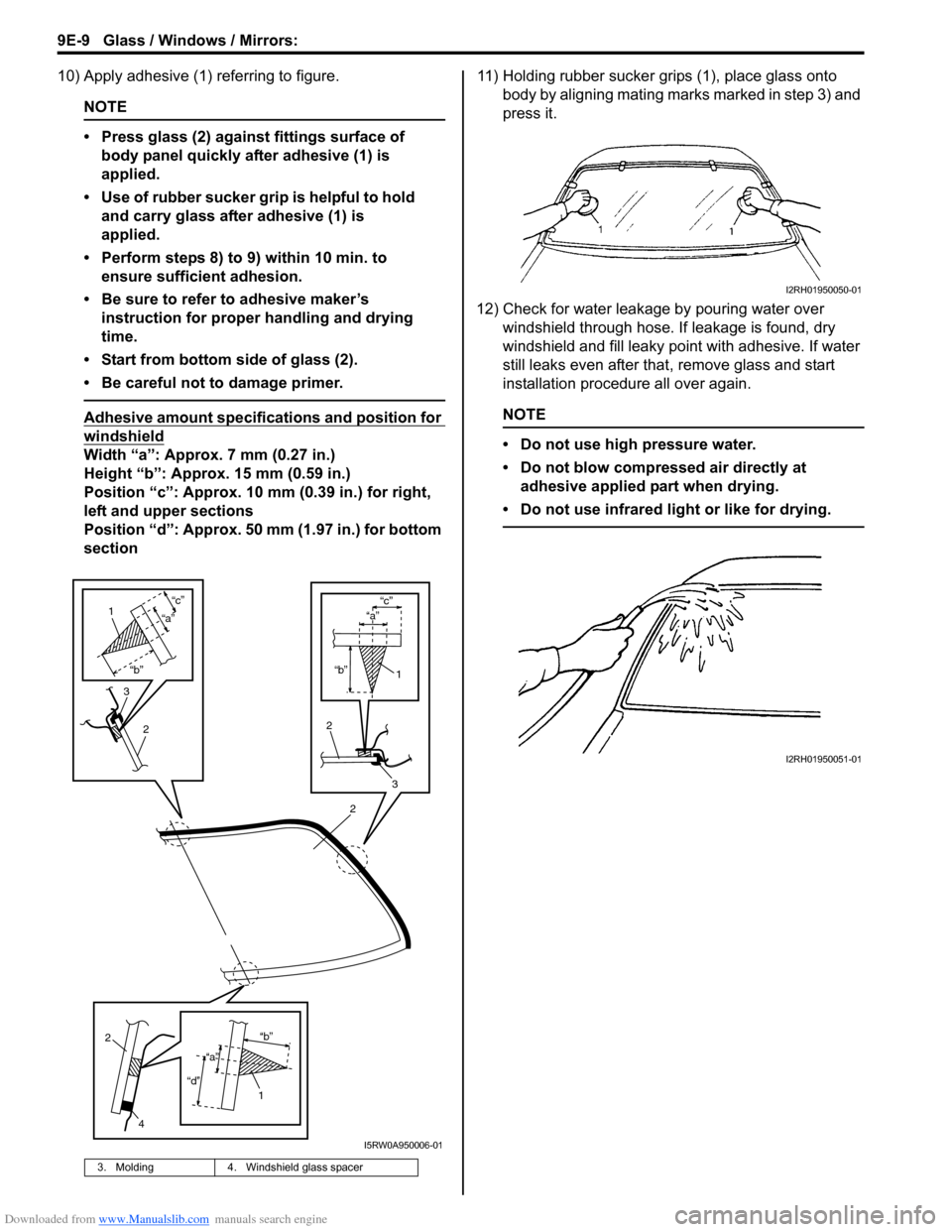
10) Apply adhesive (1) referring to figure.
NOTE
• Press glass (2) against fittings surface of
body panel quickly after adhesive (1) is
applied.
• Use of rubber sucker grip is helpful to hold
and carry glass after adhesive (1) is
applied.
• Perform steps 8) to 9) within 10 min. to
ensure sufficient adhesion.
• Be sure to refer to adhesive maker’s
instruction for proper handling and drying
time.
• Start from bottom side of glass (2).
• Be careful not to damage primer.
Adhesive amount specifications and position for
windshield
Width “a”: Approx. 7 mm (0.27 in.)
Height “b”: Approx. 15 mm (0.59 in.)
Position “c”: Approx. 10 mm (0.39 in.) for right,
left and upper sections
Position “d”: Approx. 50 mm (1.97 in.) for bottom
section11) Holding rubber sucker grips (1), place glass onto
body by aligning mating marks marked in step 3) and
press it.
12) Check for water leakage by pouring water over
windshield through hose. If leakage is found, dry
windshield and fill leaky point with adhesive. If water
still leaks even after that, remove glass and start
installation procedure all over again.
NOTE
• Do not use high pressure water.
• Do not blow compressed air directly at
adhesive applied part when drying.
• Do not use infrared light or like for drying.
3. Molding 4. Windshield glass spacer
2
“b”
“c”
2
3
1
“a”
3
2
1
“b”
“c”
“a”
2
4
1“b”
“d”
“a”
I5RW0A950006-01
I2RH01950050-01
I2RH01950051-01
Page 1397 of 1556
Downloaded from www.Manualslib.com manuals search engine Glass / Windows / Mirrors: 9E-12
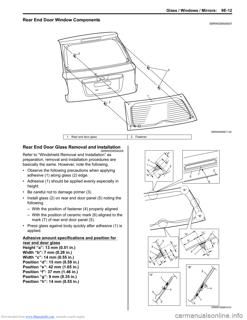
Rear End Door Window ComponentsS6RW0D9506007
Rear End Door Glass Removal and InstallationS6RW0D9506008
Refer to “Windshield Removal and Installation” as
preparation, removal and installation procedures are
basically the same. However, note the following.
• Observe the following precautions when applying
adhesive (1) along glass (2) edge.
• Adhesive (1) should be applied evenly especially in
height.
• Be careful not to damage primer (3).
• Install glass (2) on rear end door panel (5) noting the
following.
– With the position of fastener (4) properly aligned.
– With the position of ceramic mark (6) aligned to the
mark (7) of rear end door panel (5).
• Press glass against body quickly after adhesive (1) is
applied.
Adhesive amount specifications and position for
rear end door glass
Height “a”: 13 mm (0.51 in.)
Width “b”: 7 mm (0.28 in.)
Width “c”: 14 mm (0.55 in.)
Position “d”: 15 mm (0.59 in.)
Position “e”: 42 mm (1.65 in.)
Position “f”: 37 mm (1.46 in.)
Position “g”: 9 mm (0.35 in.)
Position “h”: 14 mm (0.55 in.)
2
2
1
2
I5RW0A950011-02
1. Rear end door glass 2. Fastener
“A”“a”“c”“d”1
3
12
“a”
“b”“c”
“g”
“h”
1
2
3
“A”
“B”“B” “b”
5
24
15
4 2
6
572
“a” “c”
“e”
“f ”
2
31“b”
I7RW01950010-01
Page 1398 of 1556
Downloaded from www.Manualslib.com manuals search engine 9E-13 Glass / Windows / Mirrors:
Front Door Window ComponentsS6RW0D9506009
2
8
11
4
1
7
36
9
10
12
5
I7RW01950002-01
1. Door glass 5. Door sealing cover 9. Front door inner weather-strip
2. Window regulator assembly: Apply lithium
grease 99000-25011 to sliding part.6. Door panel 10. Front door outer weather-strip
3. Glass run 7. Front door sash 11. Door trim bracket
4. Door trim 8. Door glass mounting screw: Tighten rear
screw first, and then tighten front screw.12. Door mirror trim
Page 1401 of 1556
Downloaded from www.Manualslib.com manuals search engine Glass / Windows / Mirrors: 9E-16
Rear Door Window ComponentsS6RW0D9506013
Rear Door Glass Removal and InstallationS6RW0D9506014
Removal
1) Remove rear door inner garnish (1).
2) Remove door trim mounting screws (2).3) Remove door trim (1) as shown.
2
8
12
4
6
3
13
10
11
9
7
5
1
I5RW0A950022-02
1. Door glass 6. Door sash 11. Rear door inner garnish
2. Window regulator assembly
: Apply lithium grease 99000-25011 to
sliding part.7. Door panel 12. Door trim bracket
3. Glass run 8. Rear door window regulator mounting screw
: Tighten front screws first, and then tighten rear
screws.13. Rear door outer garnish
4. Door trim 9. Rear door outer weather-strip
5. Door sealing cover 10. Rear door inner weather-strip
“A”
“A”“A”
2
1
2
I5RW0A950023-02
“A”
“A”
“A”“A”“A”
“A”
“A”“A”
“A”
1
I7RW01950009-01
Page 1407 of 1556
Downloaded from www.Manualslib.com manuals search engine Glass / Windows / Mirrors: 9E-22
Switch for Other Window than Driver Side
1) Remove driver side door trim referring to step 1) to
3) of “Front Door Glass Removal and Installation”.
2) Remove power window main switch from door trim.
3) Check for continuity between terminals as shown
below.
If check result is not as specified, replace power window
main switch.Power Window Sub Switch InspectionS6RW0D9506022
1) Remove front door trim from door panel, refer to Step
1) to 3) of “Front Door Glass Removal and
Installation”.
2) Remove power window sub switch from door trim.
3) Check for continuity between terminals at each
switch condition.
If check result is not as specified, replace switch.
[A]: Left-hand steering vehicle
[B]: Right-hand steering vehicle
I5RW0A950036-02
I5JB0A950037-01
Page 1418 of 1556
Downloaded from www.Manualslib.com manuals search engine 9F-7 Security and Locks:
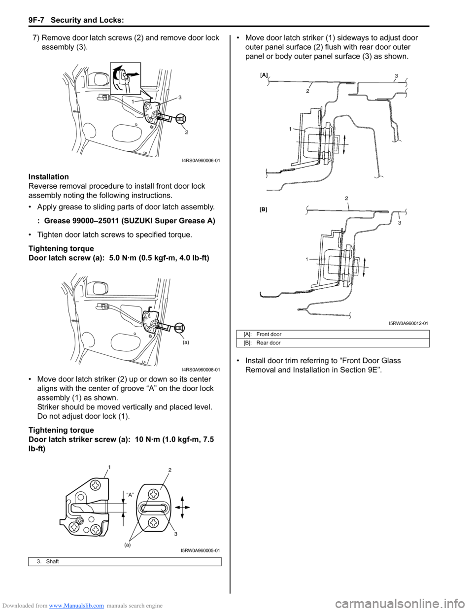
7) Remove door latch screws (2) and remove door lock
assembly (3).
Installation
Reverse removal procedure to install front door lock
assembly noting the following instructions.
• Apply grease to sliding parts of door latch assembly.
: Grease 99000–25011 (SUZUKI Super Grease A)
• Tighten door latch screws to specified torque.
Tightening torque
Door latch screw (a): 5.0 N·m (0.5 kgf-m, 4.0 lb-ft)
• Move door latch striker (2) up or down so its center
aligns with the center of groove “A” on the door lock
assembly (1) as shown.
Striker should be moved vertically and placed level.
Do not adjust door lock (1).
Tightening torque
Door latch striker screw (a): 10 N·m (1.0 kgf-m, 7.5
lb-ft)• Move door latch striker (1) sideways to adjust door
outer panel surface (2) flush with rear door outer
panel or body outer panel surface (3) as shown.
• Install door trim referring to “Front Door Glass
Removal and Installation in Section 9E”.
3. Shaft
1
2 3
I4RS0A960006-01
(a)
I4RS0A960008-01
1
2
3
(a)“A”
I5RW0A960005-01
[A]: Front door
[B]: Rear door
I5RW0A960012-01
Page 1420 of 1556
Downloaded from www.Manualslib.com manuals search engine 9F-9 Security and Locks:
Power Door Lock Actuator Inspection (If
Equipped)
S6RW0D9606006
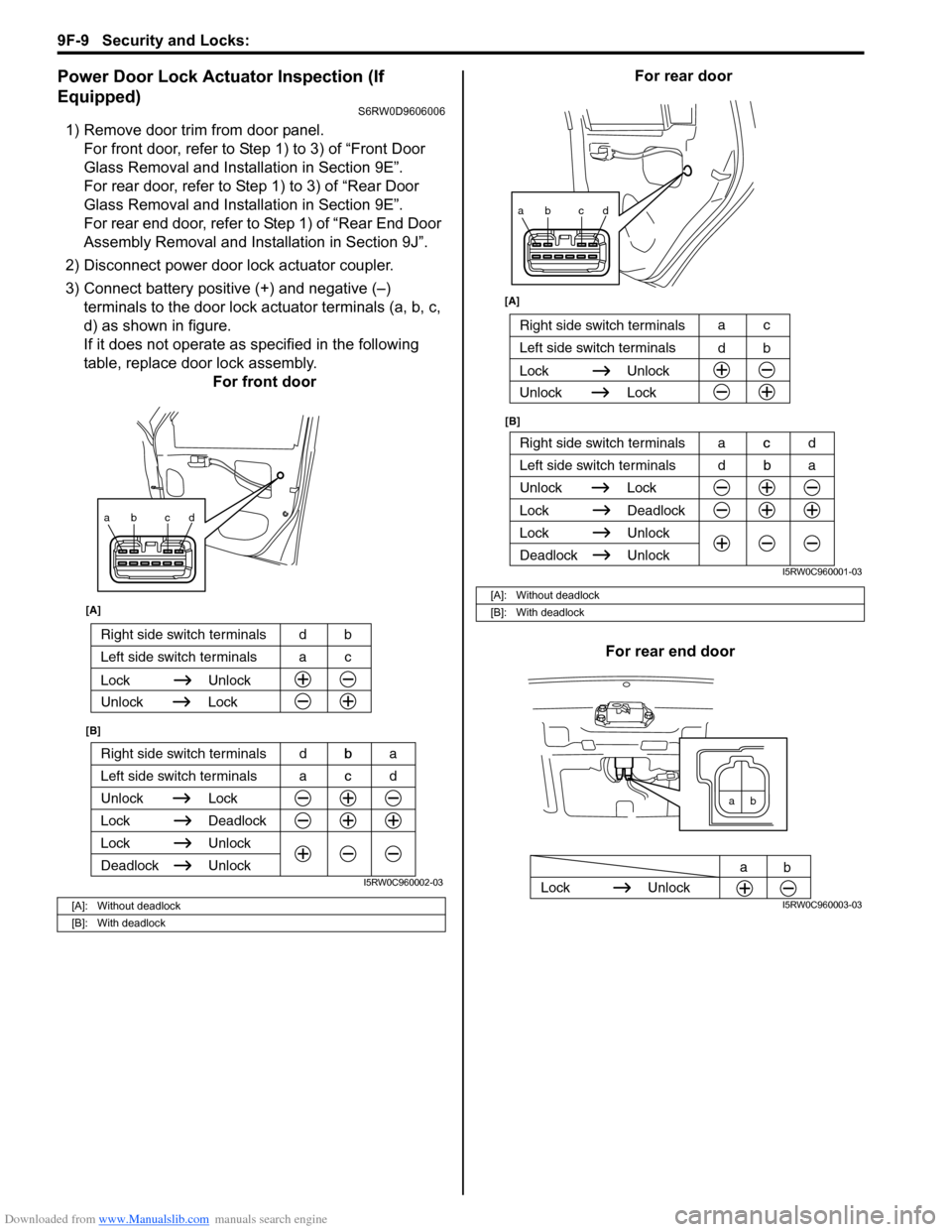
1) Remove door trim from door panel.
For front door, refer to Step 1) to 3) of “Front Door
Glass Removal and Installation in Section 9E”.
For rear door, refer to Step 1) to 3) of “Rear Door
Glass Removal and Installation in Section 9E”.
For rear end door, refer to Step 1) of “Rear End Door
Assembly Removal and Installation in Section 9J”.
2) Disconnect power door lock actuator coupler.
3) Connect battery positive (+) and negative (–)
terminals to the door lock actuator terminals (a, b, c,
d) as shown in figure.
If it does not operate as specified in the following
table, replace door lock assembly.
For front doorFor rear door
For rear end door
[A]: Without deadlock
[B]: With deadlock
ab cd
Right side switch terminals b
Unlock Lock
Lock Deadlock
Lock Unlock
Left side switch terminals c
Unlock
Deadlock
[A]
[B]
Right side switch terminals bd
Unlock Lock
Lock Unlock
Left side switch terminals ca
acd dba
I5RW0C960002-03
[A]: Without deadlock
[B]: With deadlock
ab cd
Right side switch terminals c
Unlock Lock
Lock Deadlock
Lock Unlock
Left side switch terminals b
Unlock
Deadlock
[B] [A]
Right side switch terminals
b d
Unlock Lock
Lock Unlock
Left side switch terminalsc a
dba acd
I5RW0C960001-03
ab
Lock Unlock
a
b
I5RW0C960003-03
Page 1423 of 1556
Downloaded from www.Manualslib.com manuals search engine Security and Locks: 9F-12
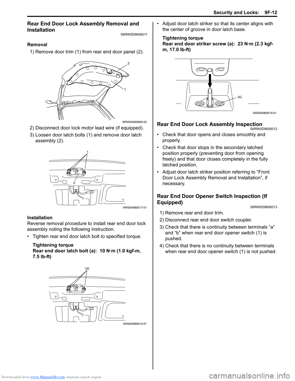
Rear End Door Lock Assembly Removal and
Installation
S6RW0D9606011
Removal
1) Remove door trim (1) from rear end door panel (2).
2) Disconnect door lock motor lead wire (if equipped).
3) Loosen door latch bolts (1) and remove door latch
assembly (2).
Installation
Reverse removal procedure to install rear end door lock
assembly noting the following instruction.
• Tighten rear end door latch bolt to specified torque.
Tightening torque
Rear end door latch bolt (a): 10 N·m (1.0 kgf-m,
7.5 lb-ft)• Adjust door latch striker so that its center aligns with
the center of groove in door latch base.
Tightening torque
Rear end door striker screw (a): 23 N·m (2.3 kgf-
m, 17.0 lb-ft)
Rear End Door Lock Assembly InspectionS6RW0D9606012
• Check that door opens and closes smoothly and
properly.
• Check that door stops in the secondary latched
position properly (preventing door from opening
freely) and that door closes completely in the fully
latched position.
• Adjust door latch striker position referring to “Front
Door Lock Assembly Removal and Installation”, if
necessary.
Rear End Door Opener Switch Inspection (If
Equipped)
S6RW0D9606013
1) Remove rear end door trim.
2) Disconnect rear end door switch coupler.
3) Check that there is continuity between terminals “a”
and “b” when rear end door opener switch (1) is
pushed.
4) Check that there is no continuity between terminals
when rear end door opener switch (1) is not pushed.
2
1
I5RW0A960008-02
1
2
I4RS0A960017-01
(a)
I4RS0A960018-01
(a)
I4RS0A960019-01