2006 SUZUKI SX4 Ac panel
[x] Cancel search: Ac panelPage 1367 of 1556
Downloaded from www.Manualslib.com manuals search engine Instrumentation / Driver Info. / Horn: 9C-15
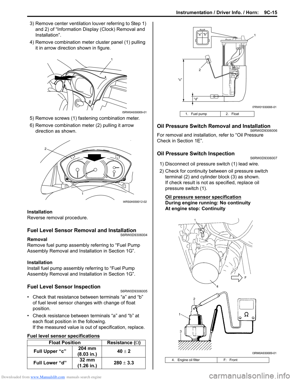
3) Remove center ventilation louver referring to Step 1)
and 2) of “Information Display (Clock) Removal and
Installation”.
4) Remove combination meter cluster panel (1) pulling
it in arrow direction shown in figure.
5) Remove screws (1) fastening combination meter.
6) Remove combination meter (2) pulling it arrow
direction as shown.
Installation
Reverse removal procedure.
Fuel Level Sensor Removal and InstallationS6RW0D9306004
Removal
Remove fuel pump assembly referring to “Fuel Pump
Assembly Removal and Installation in Section 1G”.
Installation
Install fuel pump assembly referring to “Fuel Pump
Assembly Removal and Installation in Section 1G”.
Fuel Level Sensor InspectionS6RW0D9306005
• Check that resistance between terminals “a” and “b”
of fuel level sensor changes with change of float
position.
• Check resistance between terminals “a” and “b” at
each float position in the following.
If the measured value is out of specification, replace.
Fuel level sensor specifications
Oil Pressure Switch Removal and InstallationS6RW0D9306006
For removal and installation, refer to “Oil Pressure
Check in Section 1E”.
Oil Pressure Switch InspectionS6RW0D9306007
1) Disconnect oil pressure switch (1) lead wire.
2) Check for continuity between oil pressure switch
terminal (2) and cylinder block (3) as shown.
If check result is not as specified, replace oil
pressure switch (1).
Oil pressure sensor specification
During engine running: No continuity
At engine stop: Continuity
Float Position Resistance (Ω)
Full Upper “c”204 mm
(8.03 in.)40 ± 2
Full Lower “d”32 mm
(1.26 in.)280 ± 3.3
1
I5RW0A930009-01
1
2
I4RS0A930012-02
1. Fuel pump 2. Float
4. Engine oil filter F: Front
“c”
“d”
“b” “a”1
2
I7RW01930008-01
I3RM0A930009-01
Page 1369 of 1556
Downloaded from www.Manualslib.com manuals search engine Instrumentation / Driver Info. / Horn: 9C-17
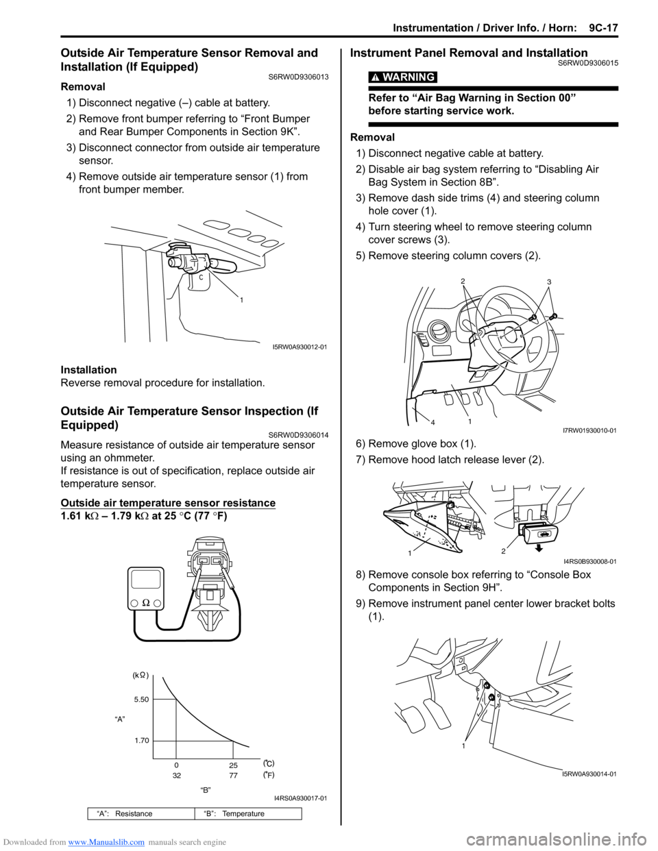
Outside Air Temperature Sensor Removal and
Installation (If Equipped)
S6RW0D9306013
Removal
1) Disconnect negative (–) cable at battery.
2) Remove front bumper referring to “Front Bumper
and Rear Bumper Components in Section 9K”.
3) Disconnect connector from outside air temperature
sensor.
4) Remove outside air temperature sensor (1) from
front bumper member.
Installation
Reverse removal procedure for installation.
Outside Air Temperature Sensor Inspection (If
Equipped)
S6RW0D9306014
Measure resistance of outside air temperature sensor
using an ohmmeter.
If resistance is out of specification, replace outside air
temperature sensor.
Outside air temperature sensor resistance
1.61 kΩ – 1.79 kΩ at 25 °C (77 °F)
Instrument Panel Removal and InstallationS6RW0D9306015
WARNING!
Refer to “Air Bag Warning in Section 00”
before starting service work.
Removal
1) Disconnect negative cable at battery.
2) Disable air bag system referring to “Disabling Air
Bag System in Section 8B”.
3) Remove dash side trims (4) and steering column
hole cover (1).
4) Turn steering wheel to remove steering column
cover screws (3).
5) Remove steering column covers (2).
6) Remove glove box (1).
7) Remove hood latch release lever (2).
8) Remove console box referring to “Console Box
Components in Section 9H”.
9) Remove instrument panel center lower bracket bolts
(1).
“A”: Resistance “B”: Temperature
1
I5RW0A930012-01
“B” “A”5.50
1.70
0
3225
77
F
I4RS0A930017-01
2
3
1
4I7RW01930010-01
2
1I4RS0B930008-01
1
I5RW0A930014-01
Page 1370 of 1556
Downloaded from www.Manualslib.com manuals search engine 9C-18 Instrumentation / Driver Info. / Horn:
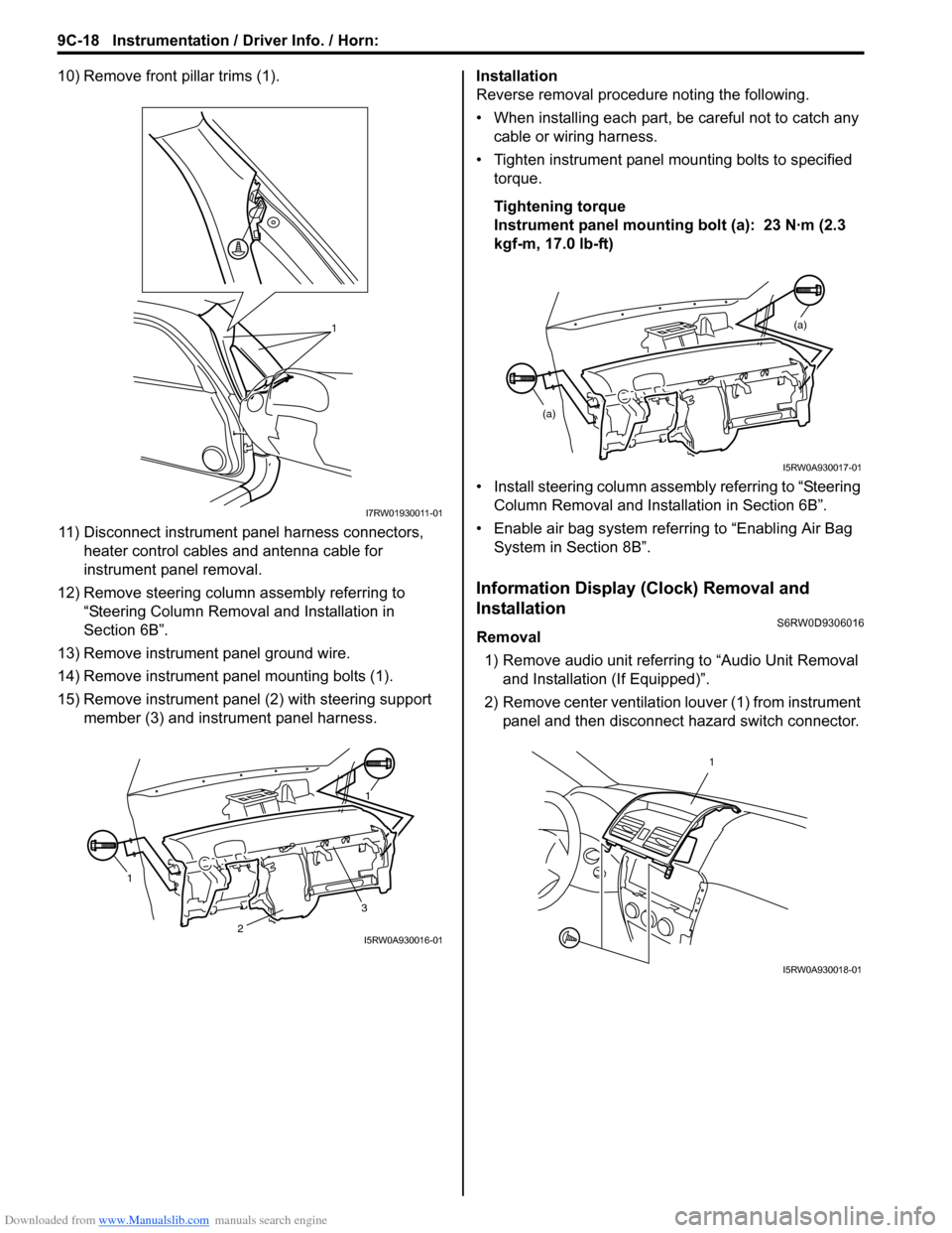
10) Remove front pillar trims (1).
11) Disconnect instrument panel harness connectors,
heater control cables and antenna cable for
instrument panel removal.
12) Remove steering column assembly referring to
“Steering Column Removal and Installation in
Section 6B”.
13) Remove instrument panel ground wire.
14) Remove instrument panel mounting bolts (1).
15) Remove instrument panel (2) with steering support
member (3) and instrument panel harness.Installation
Reverse removal procedure noting the following.
• When installing each part, be careful not to catch any
cable or wiring harness.
• Tighten instrument panel mounting bolts to specified
torque.
Tightening torque
Instrument panel mounting bolt (a): 23 N·m (2.3
kgf-m, 17.0 lb-ft)
• Install steering column assembly referring to “Steering
Column Removal and Installation in Section 6B”.
• Enable air bag system referring to “Enabling Air Bag
System in Section 8B”.
Information Display (Clock) Removal and
Installation
S6RW0D9306016
Removal
1) Remove audio unit referring to “Audio Unit Removal
and Installation (If Equipped)”.
2) Remove center ventilation louver (1) from instrument
panel and then disconnect hazard switch connector.
1
I7RW01930011-01
11
3
2I5RW0A930016-01
(a)
(a)
I5RW0A930017-01
1
I5RW0A930018-01
Page 1371 of 1556
Downloaded from www.Manualslib.com manuals search engine Instrumentation / Driver Info. / Horn: 9C-19
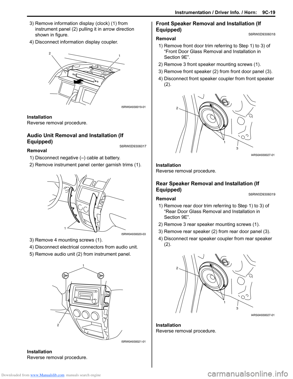
3) Remove information display (clock) (1) from
instrument panel (2) pulling it in arrow direction
shown in figure.
4) Disconnect information display coupler.
Installation
Reverse removal procedure.
Audio Unit Removal and Installation (If
Equipped)
S6RW0D9306017
Removal
1) Disconnect negative (–) cable at battery.
2) Remove instrument panel center garnish trims (1).
3) Remove 4 mounting screws (1).
4) Disconnect electrical connectors from audio unit.
5) Remove audio unit (2) from instrument panel.
Installation
Reverse removal procedure.
Front Speaker Removal and Installation (If
Equipped)
S6RW0D9306018
Removal
1) Remove front door trim referring to Step 1) to 3) of
“Front Door Glass Removal and Installation in
Section 9E”.
2) Remove 3 front speaker mounting screws (1).
3) Remove front speaker (2) from front door panel (3).
4) Disconnect front speaker coupler from front speaker
(2).
Installation
Reverse removal procedure.
Rear Speaker Removal and Installation (If
Equipped)
S6RW0D9306019
Removal
1) Remove rear door trim referring to Step 1) to 3) of
“Rear Door Glass Removal and Installation in
Section 9E”.
2) Remove 3 rear speaker mounting screws (1).
3) Remove rear speaker (2) from rear door panel (3).
4) Disconnect rear speaker coupler from rear speaker
(2).
Installation
Reverse removal procedure.
1 2
I5RW0A930019-01
1
I5RW0A930020-03
1
2
I5RW0A930021-01
1 2
3
I4RS0A930027-01
1 2
3
I4RS0A930027-01
Page 1372 of 1556
Downloaded from www.Manualslib.com manuals search engine 9C-20 Instrumentation / Driver Info. / Horn:
GPS Antenna Removal and Installation (If
Equipped)
S6RW0D9306027
Removal
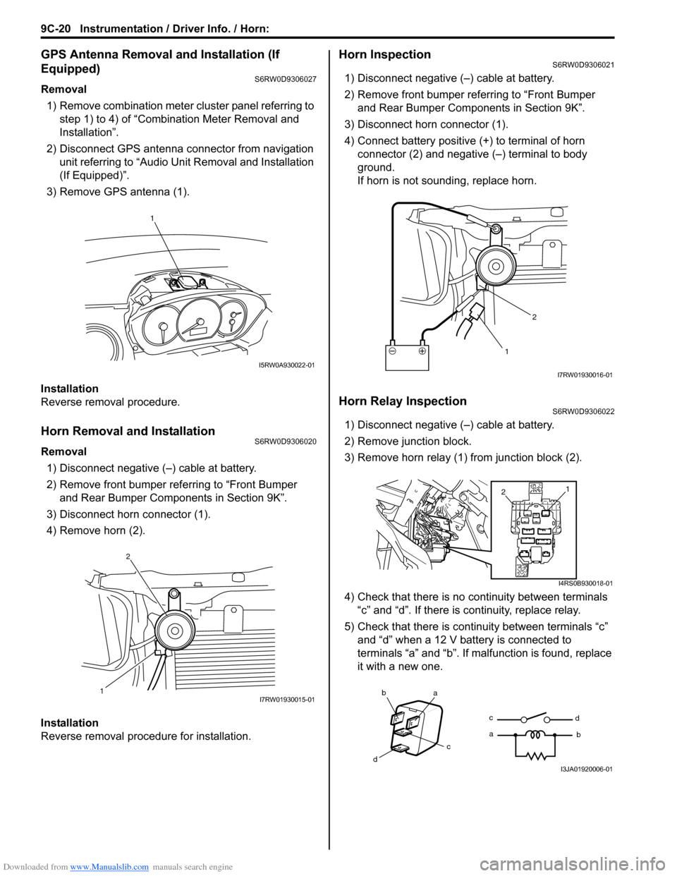
1) Remove combination meter cluster panel referring to
step 1) to 4) of “Combination Meter Removal and
Installation”.
2) Disconnect GPS antenna connector from navigation
unit referring to “Audio Unit Removal and Installation
(If Equipped)”.
3) Remove GPS antenna (1).
Installation
Reverse removal procedure.
Horn Removal and InstallationS6RW0D9306020
Removal
1) Disconnect negative (–) cable at battery.
2) Remove front bumper referring to “Front Bumper
and Rear Bumper Components in Section 9K”.
3) Disconnect horn connector (1).
4) Remove horn (2).
Installation
Reverse removal procedure for installation.
Horn InspectionS6RW0D9306021
1) Disconnect negative (–) cable at battery.
2) Remove front bumper referring to “Front Bumper
and Rear Bumper Components in Section 9K”.
3) Disconnect horn connector (1).
4) Connect battery positive (+) to terminal of horn
connector (2) and negative (–) terminal to body
ground.
If horn is not sounding, replace horn.
Horn Relay InspectionS6RW0D9306022
1) Disconnect negative (–) cable at battery.
2) Remove junction block.
3) Remove horn relay (1) from junction block (2).
4) Check that there is no continuity between terminals
“c” and “d”. If there is continuity, replace relay.
5) Check that there is continuity between terminals “c”
and “d” when a 12 V battery is connected to
terminals “a” and “b”. If malfunction is found, replace
it with a new one.
1
I5RW0A930022-01
12I7RW01930015-01
12
I7RW01930016-01
1
2
I4RS0B930018-01
ba
c
dc
ad
bI3JA01920006-01
Page 1374 of 1556
Downloaded from www.Manualslib.com manuals search engine 9C-22 Instrumentation / Driver Info. / Horn:
Remote Audio Control Switch Inspection (If
Equipped)
S6RW0D9306025
1) Remove driver air bag (inflator) module referring to
“Driver Air Bag (Inflator) Module Removal and
Installation in Section 8B”.
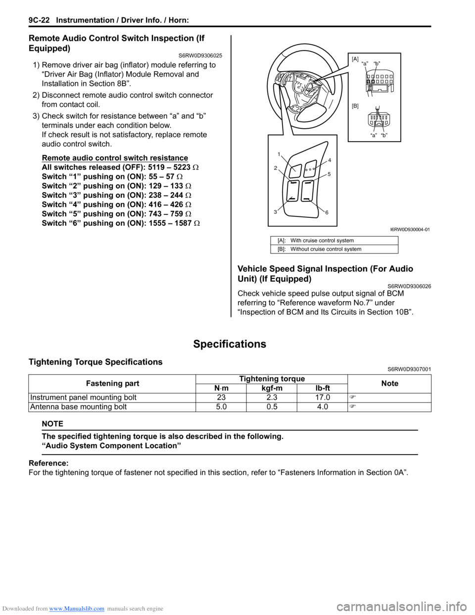
2) Disconnect remote audio control switch connector
from contact coil.
3) Check switch for resistance between “a” and “b”
terminals under each condition below.
If check result is not satisfactory, replace remote
audio control switch.
Remote audio control switch resistance
All switches released (OFF): 5119 – 5223 Ω
Switch “1” pushing on (ON): 55 – 57 Ω
Switch “2” pushing on (ON): 129 – 133 Ω
Switch “3” pushing on (ON): 238 – 244 Ω
Switch “4” pushing on (ON): 416 – 426 Ω
Switch “5” pushing on (ON): 743 – 759 Ω
Switch “6” pushing on (ON): 1555 – 1587 Ω
Vehicle Speed Signal Inspection (For Audio
Unit) (If Equipped)
S6RW0D9306026
Check vehicle speed pulse output signal of BCM
referring to “Reference waveform No.7” under
“Inspection of BCM and Its Circuits in Section 10B”.
Specifications
Tightening Torque SpecificationsS6RW0D9307001
NOTE
The specified tightening torque is also described in the following.
“Audio System Component Location”
Reference:
For the tightening torque of fastener not specified in this section, refer to “Fasteners Information in Section 0A”.
[A]: With cruise control system
[B]: Without cruise control system
1
2
34
5
6
“b” “a”
“b” “a” [A]
[B]
I6RW0D930004-01
Fastening partTightening torque
Note
N⋅mkgf-mlb-ft
Instrument panel mounting bolt 23 2.3 17.0�)
Antenna base mounting bolt 5.0 0.5 4.0�)
Page 1391 of 1556
Downloaded from www.Manualslib.com manuals search engine Glass / Windows / Mirrors: 9E-6
Windshield Removal and InstallationS6RW0D9506002
Preparation
The windshield is installed by using a special type of
adhesive (that is, one component urethane adhesive
used with primer). For the windshield replacement, it is
important to use an adhesive which provides sufficient
adhesion strength and follow the proper procedure.
CAUTION!
• Described is the glass replacement by
using 3 types of primers and 1 type of
adhesive made by YOKOHAMA (one
component urethane adhesive to be used
with primer in combination). When using
primer and adhesive made by other
manufacturers, be sure to refer to handling
instructions supplied with them.
Negligence in following such procedure or
misuse of the adhesive in any way hinders
its inherent adhesive property. Therefore,
before the work, make sure to read
carefully the instruction and description
given by the maker of the adhesive to be
used and be sure to follow the procedure
and observe each precaution throughout
the work.
• Should coated surface be scratched or
otherwise damaged, be sure to repair
damaged part, or corrosion may start from
there.
Use the specific adhesive which has the following
property.
Glass adhesive shearing strength
40 kg/cm2 (569 lb/in2) or moreAdhesive materials and tools required for removal and
installation.
• One component urethane adhesive and primers used
in combination (For one sheet of windshield).
– Adhesive (470 g (15.7 oz.))
– Primer for glass (30 g (1.0 oz.))
– Primer for body (30 g (1.0 oz.))
– Primer for molding (30 g (1.0 oz.))
• Eyeleteer
•Piano string
• Windshield knife
• Brush for primer application (2 pcs)
•Knife
• Rubber sucker grip
• Sealant gun (for filling adhesive)
• Putty spatula (for correcting adhered parts)
Removal
1) Clean both inside and outside of glass and around it.
2) Remove wiper arms and cowl top garnish.
3) Using tape, cover body surface around glass to
prevent any damage.
4) Remove rear view mirror, sun visor and front pillar
trims (right & left).
5) If necessary, remove instrument panel. Refer to
“Instrument Panel Removal and Installation in
Section 9C”.
6) If necessary, remove head lining. Refer to “Head
Lining Removal and Installation in Section 9H”.
7) Remove (or cut) windshield molding.
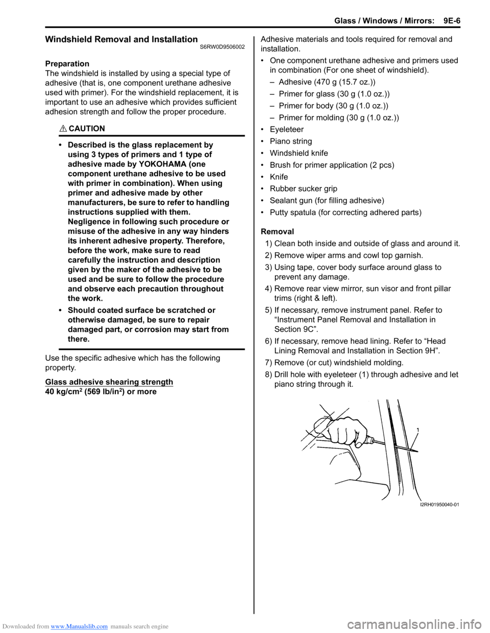
8) Drill hole with eyeleteer (1) through adhesive and let
piano string through it.
I2RH01950040-01
Page 1392 of 1556
Downloaded from www.Manualslib.com manuals search engine 9E-7 Glass / Windows / Mirrors:
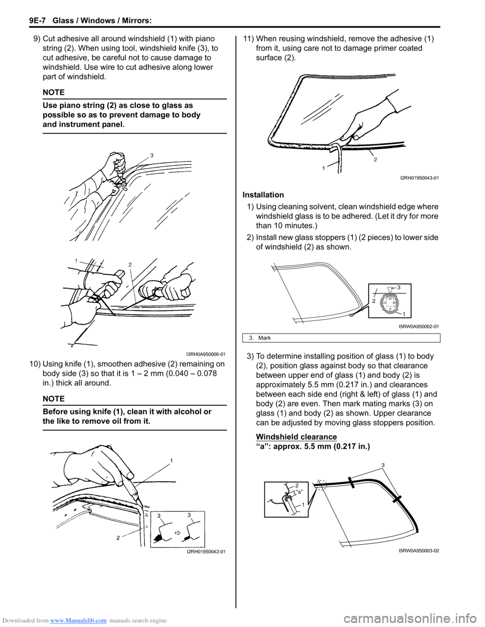
9) Cut adhesive all around windshield (1) with piano
string (2). When using tool, windshield knife (3), to
cut adhesive, be careful not to cause damage to
windshield. Use wire to cut adhesive along lower
part of windshield.
NOTE
Use piano string (2) as close to glass as
possible so as to prevent damage to body
and instrument panel.
10) Using knife (1), smoothen adhesive (2) remaining on
body side (3) so that it is 1 – 2 mm (0.040 – 0.078
in.) thick all around.
NOTE
Before using knife (1), clean it with alcohol or
the like to remove oil from it.
11) When reusing windshield, remove the adhesive (1)
from it, using care not to damage primer coated
surface (2).
Installation
1) Using cleaning solvent, clean windshield edge where
windshield glass is to be adhered. (Let it dry for more
than 10 minutes.)
2) Install new glass stoppers (1) (2 pieces) to lower side
of windshield (2) as shown.
3) To determine installing position of glass (1) to body
(2), position glass against body so that clearance
between upper end of glass (1) and body (2) is
approximately 5.5 mm (0.217 in.) and clearances
between each side end (right & left) of glass (1) and
body (2) are even. Then mark mating marks (3) on
glass (1) and body (2) as shown. Upper clearance
can be adjusted by moving glass stoppers position.
Windshield clearance
“a”: approx. 5.5 mm (0.217 in.)
I3RH0A950006-01
I2RH01950042-01
3. Mark
I2RH01950043-01
1
3
2
I5RW0A950002-01
2
1“a”
3
I5RW0A950003-02