2006 SUZUKI SX4 Ac panel
[x] Cancel search: Ac panelPage 1446 of 1556
Downloaded from www.Manualslib.com manuals search engine 9K-2 Body Structure:
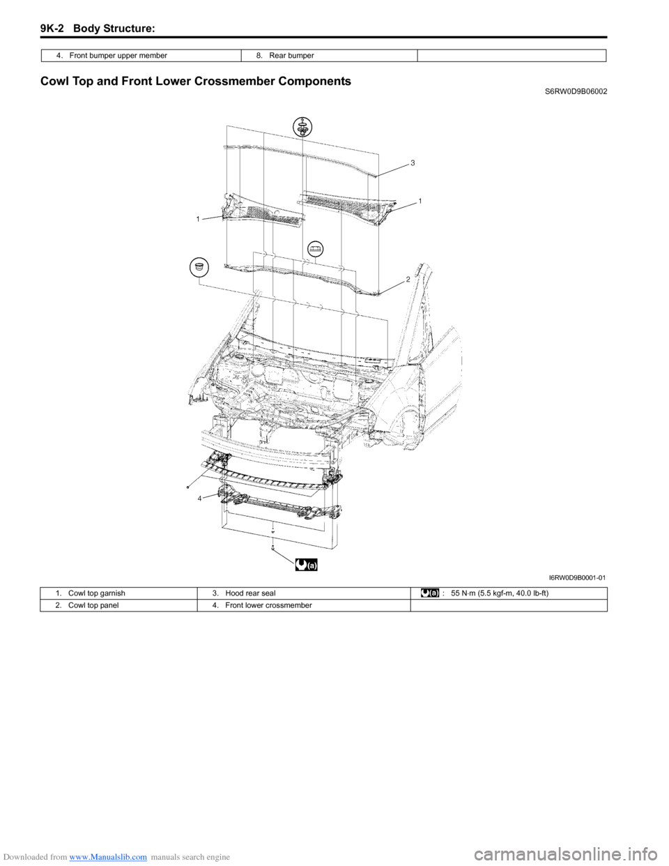
Cowl Top and Front Lower Crossmember ComponentsS6RW0D9B06002 4. Front bumper upper member 8. Rear bumper
I6RW0D9B0001-01
1. Cowl top garnish 3. Hood rear seal : 55 N⋅m (5.5 kgf-m, 40.0 lb-ft)
2. Cowl top panel 4. Front lower crossmember
Page 1449 of 1556
Downloaded from www.Manualslib.com manuals search engine Body Structure: 9K-5
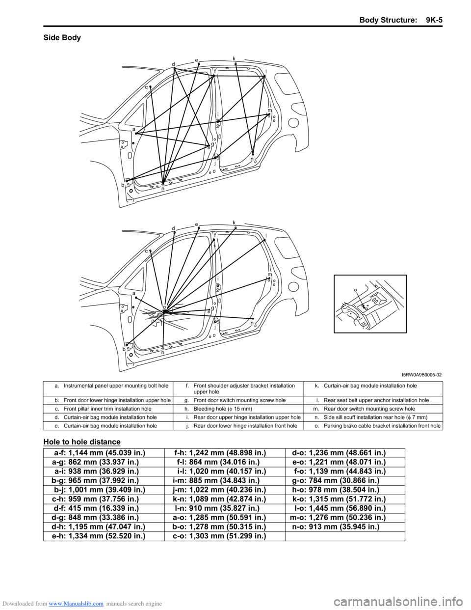
Side Body
Hole to hole distance
o
dek
fl
im
n
g
j
h
o
ac
b
dek
fl
im
n
g
j
h
ac
b
I5RW0A9B0005-02
a. Instrumental panel upper mounting bolt hole f. Front shoulder adjuster bracket installation
upper holek. Curtain-air bag module installation hole
b. Front door lower hinge installation upper hole g. Front door switch mounting screw hole l. Rear seat belt upper anchor installation hole
c. Front pillar inner trim installation hole h. Bleeding hole (φ 15 mm) m. Rear door switch mounting screw hole
d. Curtain-air bag module installation hole i. Rear door upper hinge installation upper hole n. Side sill scuff installation rear hole (φ 7 mm)
e. Curtain-air bag module installation hole j. Rear door lower hinge installation front hole o. Parking brake cable bracket installation front hole
a-f: 1,144 mm (45.039 in.) f-h: 1,242 mm (48.898 in.) d-o: 1,236 mm (48.661 in.)
a-g: 862 mm (33.937 in.) f-l: 864 mm (34.016 in.) e-o: 1,221 mm (48.071 in.)
a-i: 938 mm (36.929 in.) i-l: 1,020 mm (40.157 in.) f-o: 1,139 mm (44.843 in.)
b-g: 965 mm (37.992 in.) i-m: 885 mm (34.843 in.) g-o: 784 mm (30.866 in.)
b-j: 1,001 mm (39.409 in.) j-m: 1,022 mm (40.236 in.) h-o: 978 mm (38.504 in.)
c-h: 959 mm (37.756 in.) k-n: 1,089 mm (42.874 in.) k-o: 1,315 mm (51.772 in.)
d-f: 415 mm (16.339 in.) l-n: 910 mm (35.827 in.) l-o: 1,445 mm (56.890 in.)
d-g: 848 mm (33.386 in.) a-o: 1,285 mm (50.591 in.) m-o: 1,276 mm (50.236 in.)
d-h: 1,195 mm (47.047 in.) b-o: 1,278 mm (50.315 in.) n-o: 913 mm (35.945 in.)
e-h: 1,334 mm (52.520 in.) c-o: 1,303 mm (51.299 in.)
Page 1454 of 1556
Downloaded from www.Manualslib.com manuals search engine 9K-10 Body Structure:
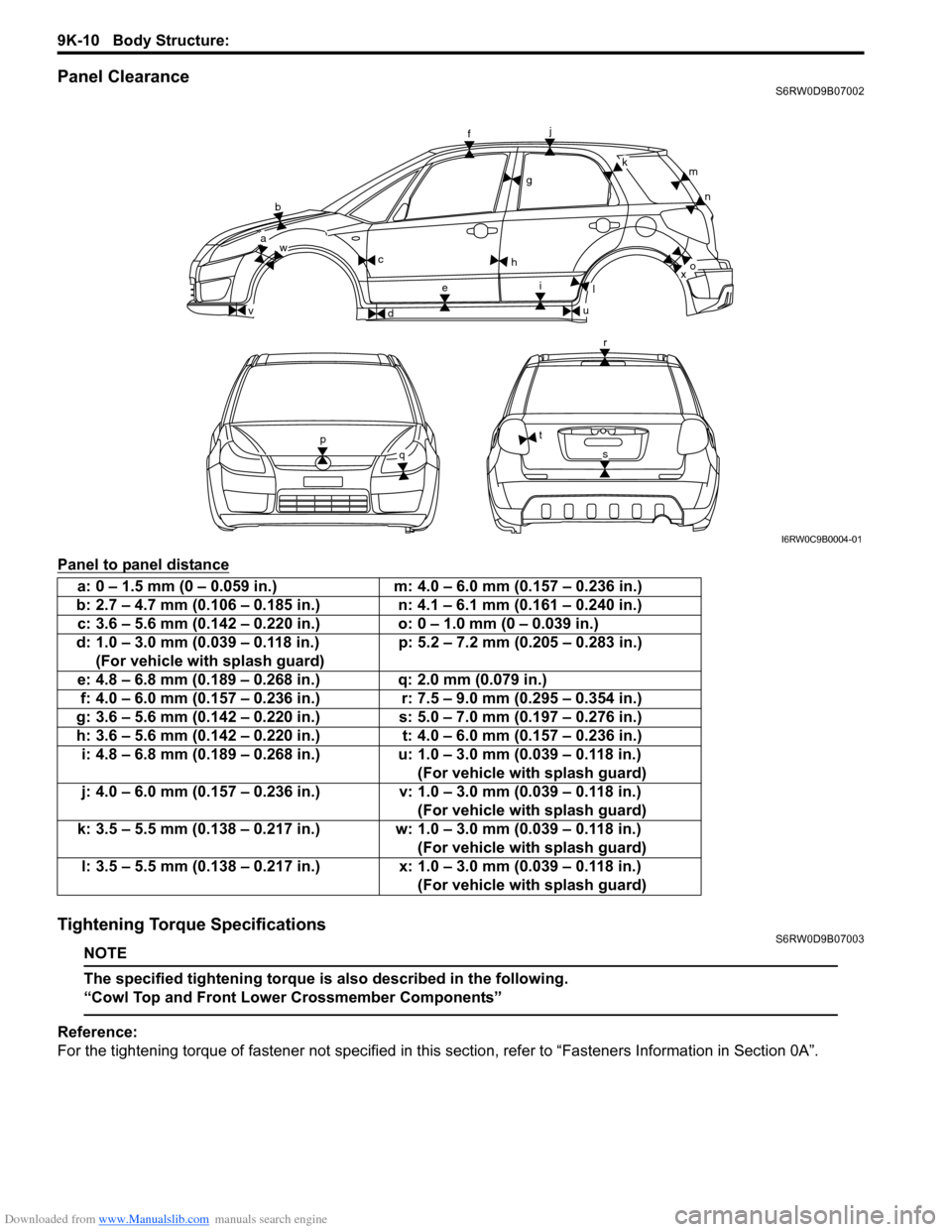
Panel ClearanceS6RW0D9B07002
Panel to panel distance
Tightening Torque SpecificationsS6RW0D9B07003
NOTE
The specified tightening torque is also described in the following.
“Cowl Top and Front Lower Crossmember Components”
Reference:
For the tightening torque of fastener not specified in this section, refer to “Fasteners Information in Section 0A”.
b
wa
v
c
d
f
g
j
h
ei
u
l
km
n
xo
r
t
sp
q
I6RW0C9B0004-01
a: 0 – 1.5 mm (0 – 0.059 in.) m: 4.0 – 6.0 mm (0.157 – 0.236 in.)
b: 2.7 – 4.7 mm (0.106 – 0.185 in.) n: 4.1 – 6.1 mm (0.161 – 0.240 in.)
c: 3.6 – 5.6 mm (0.142 – 0.220 in.) o: 0 – 1.0 mm (0 – 0.039 in.)
d: 1.0 – 3.0 mm (0.039 – 0.118 in.)
(For vehicle with splash guard)p: 5.2 – 7.2 mm (0.205 – 0.283 in.)
e: 4.8 – 6.8 mm (0.189 – 0.268 in.) q: 2.0 mm (0.079 in.)
f: 4.0 – 6.0 mm (0.157 – 0.236 in.) r: 7.5 – 9.0 mm (0.295 – 0.354 in.)
g: 3.6 – 5.6 mm (0.142 – 0.220 in.) s: 5.0 – 7.0 mm (0.197 – 0.276 in.)
h: 3.6 – 5.6 mm (0.142 – 0.220 in.) t: 4.0 – 6.0 mm (0.157 – 0.236 in.)
i: 4.8 – 6.8 mm (0.189 – 0.268 in.) u: 1.0 – 3.0 mm (0.039 – 0.118 in.)
(For vehicle with splash guard)
j: 4.0 – 6.0 mm (0.157 – 0.236 in.) v: 1.0 – 3.0 mm (0.039 – 0.118 in.)
(For vehicle with splash guard)
k: 3.5 – 5.5 mm (0.138 – 0.217 in.) w: 1.0 – 3.0 mm (0.039 – 0.118 in.)
(For vehicle with splash guard)
l: 3.5 – 5.5 mm (0.138 – 0.217 in.) x: 1.0 – 3.0 mm (0.039 – 0.118 in.)
(For vehicle with splash guard)
Page 1455 of 1556
Downloaded from www.Manualslib.com manuals search engine Paint / Coatings: 9L-1
Body, Cab and Accessories
Paint / Coatings
General Description
Anti-Corrosion Treatment ConstructionS6RW0D9C01001
WARNING!
Standard shop practices, particularly eye protection, should be followed during the performance of the
following operations to avoid personal injury.
As rust proof treatment, steel sheets are given corrosion resistance on the interior and/or exterior.
These corrosion resistance steel sheet materials are called one of two-side galvanized steel sheets.
It is for the sake of rust protection that these materials are selected and given a variety of treatments as described
blow.
• Steel sheets are treated with cathodic electro primer which is excellent in corrosion resistance.
• Rust proof wax coatings are applied to door and side sill insides where moisture is liable to stay.
• Vinyl coating is applied to body underside and wheel housing inside.
• Sealer is applied to door hem, engine compartment steel sheet-to-steel sheet joint, and the like portions to prevent
water penetration and resulting in rust occurrence.
In panel replacement or collision damage repair, leaving the relevant area untreated as it is in any operation which
does disturb the rust proof treatment will cause corrosion to that area. Therefore, it is the essential function of any
repair operation to correctly recoat the related surfaces of the relevant area.
All the metal panels are coated with metal conditioners and primer coating during vehicle production. Following the
repair and/or replacement parts installation, every accessible bare metal surface should be cleaned and coated with
rust proof primer. Perform this operation prior to the application of sealer and rust proof wax coating.
Sealer is applied to the specific joints of a vehicle during production. The sealer is intended to prevent dust from
entering the vehicle and serves also as an anticorrosion barrier. The sealer is applied to the door and hood hem areas
and between panels. Correct and reseal the originally sealed joints if damaged. Reseal the attaching joints of a new
replacement panel and reseal the hem area of a replacement door or hood.
Use a quality sealer to seal the flanged joints, overlap joints and seams. The sealer must have flexible characteristics
and paint ability after it’s applied to repair areas.
For the sealer to fill open joints, use caulking material. Select a sealer in conformance with the place and purpose of a
specific use. Observe the manufacturer’s label-stand instructions when using the sealer.
In many cases, repaired places require color painting. When this is required, follow the ordinary techniques specified
for the finish preparation, color painting and undercoating build-up.
Rust proof wax, a penetrative compound, is applied to the metal-to-metal surfaces (door and side sill insides) where it
is difficult to use ordinary undercoating material for coating. Therefore, when selecting the rust proof wax, it may be the
penetrative type.
During the undercoating (vinyl coating) application, care should be taken that sealer is not applied to the engine-
related parts and shock absorber mounting or rotating parts. Following the under coating, make sure that body drain
holes are kept open.
The sequence of the application steps of the anti-corrosion materials are as follows:
1) Clean and prepare the metal surface.
2) Apply primer.
3) Apply sealer (all joints sealed originally).
4) Apply color in areas where color is required such as hem flanges, exposed joints and under body components.
5) Apply anticorrosion compound (penetrative wax).
6) Apply undercoating (rust proof material).
Page 1468 of 1556
Downloaded from www.Manualslib.com manuals search engine 9M-1 Exterior Trim:
Body, Cab and Accessories
Exterior Trim
Repair Instructions
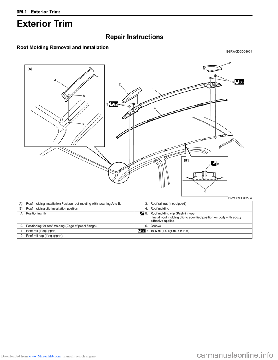
Roof Molding Removal and InstallationS6RW0D9D06001
2
312
3
44 [A]
A
B
[B]
5
6
(a)
(a)
I5RW0C9D0002-04
[A]: Roof molding installation Position roof molding with touching A to B. 3. Roof rail nut (if equipped)
[B]: Roof molding clip installation position 4. Roof molding
A: Positioning rib 5. Roof molding clip (Push-in type)
: Install roof molding clip to specified position on body with epoxy
adhesive applied.
B: Positioning for roof molding (Edge of panel flange) 6. Groove
1. Roof rail (if equipped) : 10 N⋅m (1.0 kgf-m, 7.5 lb-ft)
2. Roof rail cap (if equipped)
Page 1471 of 1556
Downloaded from www.Manualslib.com manuals search engine Table of Contents 10- i
10
Section 10
CONTENTS
Control Systems
Precautions ............................................... 10-1
Precautions........................................................... 10-1
Precautions for Control Systems......................... 10-1
Body Electrical Control System ........... 10B-1
Precautions......................................................... 10B-1
Precautions in Diagnosing Trouble ................... 10B-1
General Description ........................................... 10B-1
BCM General Description ................................. 10B-1
CAN Communication System Description......... 10B-1
Theft Deterrent Light ......................................... 10B-2
Security Alarm Description (If Equipped) .......... 10B-2
Schematic and Routing Diagram ...................... 10B-3
Body Electrical Control System Wiring Circuit
Diagram .......................................................... 10B-3
Connector Layout Diagram of BCM and
Junction Block ................................................. 10B-6
Component Location ......................................... 10B-7
BCM and Related System Component
Location .......................................................... 10B-7
Diagnostic Information and Procedures .......... 10B-8
BCM Self-Diagnosis Function ........................... 10B-8
Body Electrical Control System Check.............. 10B-9
Scan Tool Data ............................................... 10B-11
DTC Table ....................................................... 10B-13
DTC Check ..................................................... 10B-14
DTC Clearance ............................................... 10B-15
BCM Power Circuit and Ground Circuit Check 10B-16
DTC B1133 (DTC No. 1133): Battery Voltage
Too High ....................................................... 10B-17
DTC B1141 / DTC B1142 (No. 1141 / No.
1142) Outside Air Temperature (Ambient
Temp.) Sensor Circuit Malfunction ................ 10B-18
DTC B1150 (No. 1150): Air Bag
Communication Circuit Malfunction .............. 10B-19
DTC B1157 (No. 1157) Air Bag Deployment
Signal Input ................................................... 10B-20
DTC B1170 (No. 1170): EEPROM Access
Error .............................................................. 10B-20
DTC U0073 (No. 0073): Control Module
Communication Bus Off ................................ 10B-20
DTC U0100 (No. 0100): Lost Communication
with ECM....................................................... 10B-20DTC U0101 (No. 0101): Lost Communication
with TCM ....................................................... 10B-20
DTC U0155 (No. 0155): Lost Communication
with Instrument Panel Cluster (IPC) Control
Module .......................................................... 10B-20
DTC U1144 (No. 1144): Lost Communication
with Keyless Start Control Module ................ 10B-20
Inspection of BCM and Its Circuits .................. 10B-21
Repair Instructions ..........................................10B-28
BCM (Included in Junction Block) Removal
and Installation .............................................. 10B-28
Security Alarm Mode Selection Procedure (If
Equipped) ...................................................... 10B-29
Outside Air Temperature Sensor Removal
and Installation .............................................. 10B-29
Outside Air Temperature Sensor Inspection ... 10B-29
Special Tools and Equipment .........................10B-29
Special Tool .................................................... 10B-29
Immobilizer Control System ................. 10C-1
Precautions.........................................................10C-1
Precautions in Diagnosing Troubles .................10C-1
Precaution in Replacing ECM ...........................10C-1
Precaution in Replacing Ignition Key ................10C-1
Precautions in Handling Immobilizer Control
System ............................................................10C-1
General Description ...........................................10C-2
Immobilizer Control System Introduction ..........10C-2
On-Board Diagnostic System Description
(Self-diagnosis Function)................................10C-2
Schematic and Routing Diagram ......................10C-3
Immobilizer Control System Wiring Circuit
Diagram...........................................................10C-3
Component Location .........................................10C-5
Immobilizer Control System Components
Location...........................................................10C-5
Diagnostic Information and Procedures ..........10C-5
Immobilizer Control System Check ...................10C-5
DTC Check........................................................10C-6
DTC Clearance .................................................10C-6
DTC Table .........................................................10C-7
Scan Tool Data .................................................10C-8
Immobilizer Indicator Light Does Not Come
ON with Ignition Switch ON and Engine Stop ..10C-9
Page 1486 of 1556
Downloaded from www.Manualslib.com manuals search engine 10B-13 Body Electrical Control System:
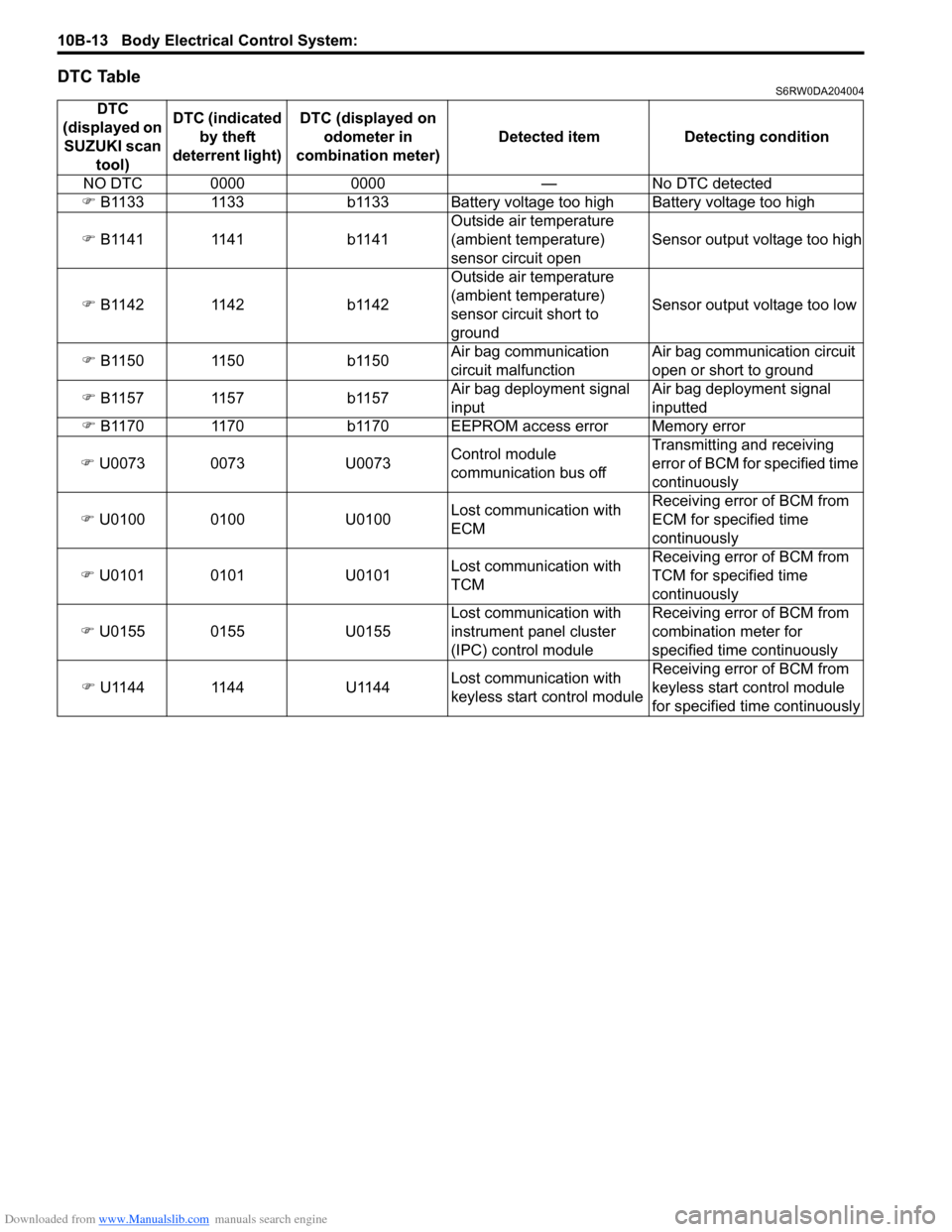
DTC TableS6RW0DA204004
DTC
(displayed on
SUZUKI scan
tool)DTC (indicated
by theft
deterrent light) DTC (displayed on
odometer in
combination meter) Detected item Detecting condition
NO DTC 0000 0000 — No DTC detected
�) B1133 1133 b1133 Battery voltage too high Battery voltage too high
�) B1141 1141 b1141Outside air temperature
(ambient temperature)
sensor circuit openSensor output voltage too high
�) B1142 1142 b1142Outside air temperature
(ambient temperature)
sensor circuit short to
groundSensor output voltage too low
�) B1150 1150 b1150Air bag communication
circuit malfunctionAir bag communication circuit
open or short to ground
�) B1157 1157 b1157Air bag deployment signal
inputAir bag deployment signal
inputted
�) B1170 1170 b1170 EEPROM access error Memory error
�) U0073 0073 U0073Control module
communication bus offTransmitting and receiving
error of BCM for specified time
continuously
�) U0100 0100 U0100Lost communication with
ECMReceiving error of BCM from
ECM for specified time
continuously
�) U0101 0101 U0101Lost communication with
TCMReceiving error of BCM from
TCM for specified time
continuously
�) U0155 0155 U0155Lost communication with
instrument panel cluster
(IPC) control moduleReceiving error of BCM from
combination meter for
specified time continuously
�) U1144 1144 U1144Lost communication with
keyless start control moduleReceiving error of BCM from
keyless start control module
for specified time continuously
Page 1487 of 1556
Downloaded from www.Manualslib.com manuals search engine Body Electrical Control System: 10B-14
DTC CheckS6RW0DA204005
Using SUZUKI Scan Tool
1) Prepare SUZUKI scan tool.
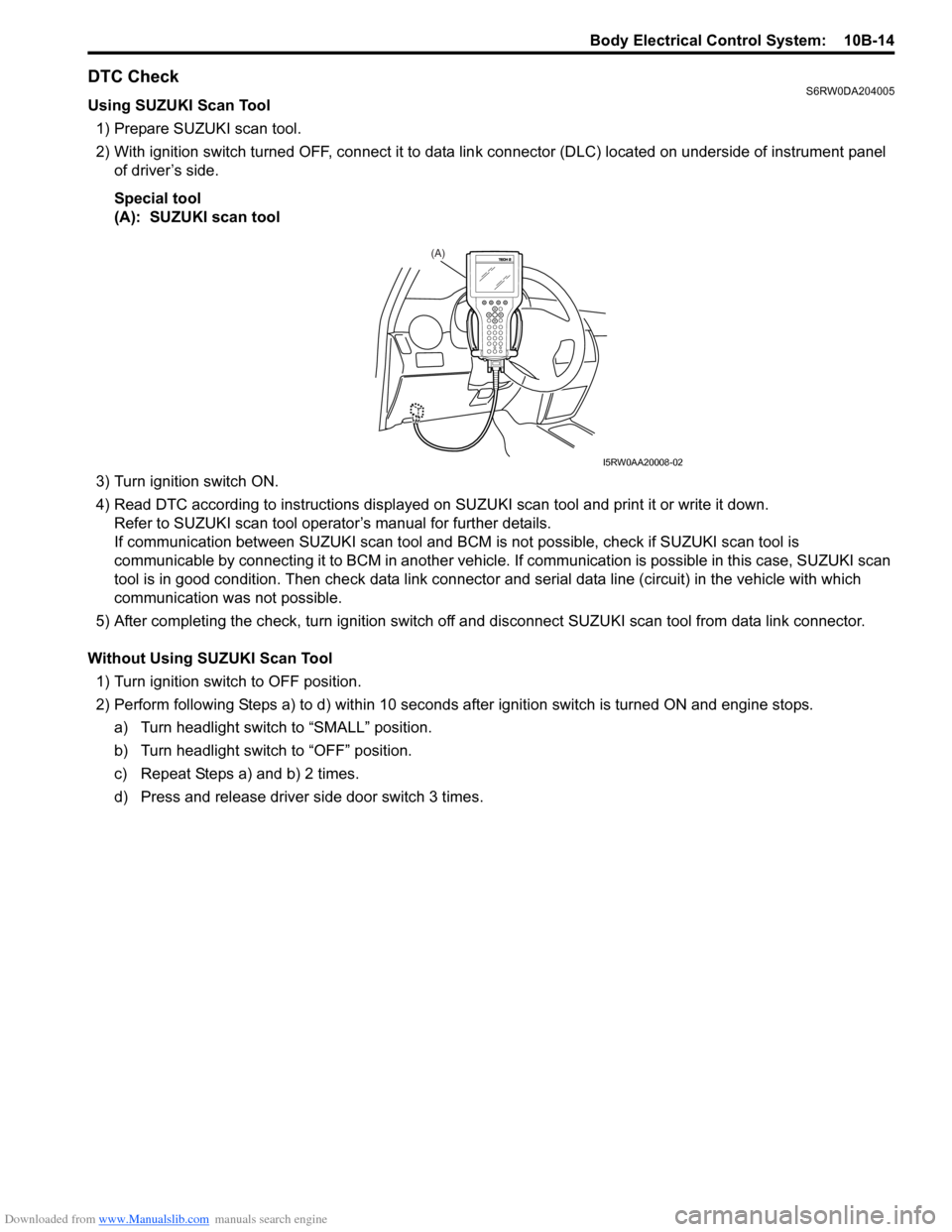
2) With ignition switch turned OFF, connect it to data link connector (DLC) located on underside of instrument panel
of driver’s side.
Special tool
(A): SUZUKI scan tool
3) Turn ignition switch ON.
4) Read DTC according to instructions displayed on SUZUKI scan tool and print it or write it down.
Refer to SUZUKI scan tool operator’s manual for further details.
If communication between SUZUKI scan tool and BCM is not possible, check if SUZUKI scan tool is
communicable by connecting it to BCM in another vehicle. If communication is possible in this case, SUZUKI scan
tool is in good condition. Then check data link connector and serial data line (circuit) in the vehicle with which
communication was not possible.
5) After completing the check, turn ignition switch off and disconnect SUZUKI scan tool from data link connector.
Without Using SUZUKI Scan Tool
1) Turn ignition switch to OFF position.
2) Perform following Steps a) to d) within 10 seconds after ignition switch is turned ON and engine stops.
a) Turn headlight switch to “SMALL” position.
b) Turn headlight switch to “OFF” position.
c) Repeat Steps a) and b) 2 times.
d) Press and release driver side door switch 3 times.
(A)
I5RW0AA20008-02