2006 SUZUKI SX4 Timing
[x] Cancel search: TimingPage 740 of 1556

Downloaded from www.Manualslib.com manuals search engine 5A-92 Automatic Transmission/Transaxle:
Installation
Reverse removal procedure to install valve body
harness and valve body assembly noting the following
points.
• For details of valve body assembly and their
connectors installation, refer to “Automatic Transaxle
Unit Assembly”.
• For details of A/T oil pan installation, refer to
“Automatic Transaxle Unit Assembly”. Use new oil
pan gasket.
• Tighten valve body harness connector bolt to
specified torque.
Tightening torque
Valve body harness connector bolt (a): 5.5 N·m (
0.55 kgf-m, 4.0 lb-ft)
• Pour A/T fluid and check fluid level according to
procedure described in “A/T Fluid Change”.
• Check for fluid leakage after warming up A/T.Transmission Fluid Temperature Sensor
Inspection
S6RW0D5106015
Warm up transmission fluid temperature sensor (2).
Check resistance between terminals of valve body
harness connector (1). Thus make sure its resistance
decrease as its temperature increase.
Transmission fluid temperature sensor resistance
10 °C (50 °F): 5.8 – 7.1 kΩ
11 0 °C (230 °F): 231 – 263 Ω
145 °C (293 °F): 105 – 117 Ω
Solenoid Valves (Shift Solenoid Valves and
Timing Solenoid Valve) Removal and
Installation
S6RW0D5106061
Removal
1) Disconnect negative cable at battery.
2) Lift up vehicle.
3) Remove left side engine under cover.
4) Remove drain plug and drain A/T fluid.
5) Install drain plug.
Tightening torque
A/T fluid drain plug: 17 N·m (1.7 kgf-m, 12.5 lb-ft)
6) Remove A/T oil pan (1) and oil pan gasket (2).
I2RH0B510051-01
I2RH0B510052-01
Page 741 of 1556

Downloaded from www.Manualslib.com manuals search engine Automatic Transmission/Transaxle: 5A-93
7) Remove oil strainer assembly (3).
8) Remove transmission fluid temperature sensor (1)
from sensor clamp.
9) Disconnect solenoid connectors (2).
10) Remove shift solenoid valve-A (No.1) (1), shift
solenoid valve-B (No.2) (2) and timing solenoid valve
(3) by removing bolts.Installation
1) Install shift solenoid valve-A (No.1) (1), shift solenoid
valve-B (No.2) (2) and timing solenoid valve (3).
Tightening torque
Shift solenoid bolt (a): 11 N·m (1.1 kgf-m, 8.0 lb-
ft)
2) Connect solenoid connectors identifying their
installing positions by wire color.
3) Install transmission fluid sensor (6) and sensor wire
to clamp.
I2RH0B510054-01
2
1
I5RW0C510038-02
12
3
I4RS0A510028-01
Solenoid coupler Wire color
Shift solenoid valve-A (No.1) (2) White
Shift solenoid valve-B (No.2) (3) Black
Timing solenoid valve (1) Yellow
TCC pressure control solenoid
valve (4)Light green / Brown
Pressure control solenoid valve
(5)Green / Gray
12
3 (a)
I4RS0A510029-01
2 4
6
1
3
5
I5RW0C510039-02
Page 742 of 1556

Downloaded from www.Manualslib.com manuals search engine 5A-94 Automatic Transmission/Transaxle:
4) Install oil strainer assembly (1).
Tightening torque
Oil strainer bolt (a): 10 N·m (1.0 kgf-m, 7.5 lb-ft)
5) Install new oil pan gasket (1) and oil pan (2).
6) Tighten oil pan bolts to specified torque diagonally
and little by little.
Tightening torque
Oil pan bolt (b): 7.0 N·m (0.7 kgf-m, 5.0 lb-ft)
7) Install left side engine under cover.
8) Lower vehicle.
9) Connect negative cable at battery.
Solenoid Valves (Shift Solenoid Valves and
Timing Solenoid Valve) Inspection
S6RW0D5106062
Resistance Check
Check shift solenoid valves and timing solenoid valve.
Shift solenoid valves and timing solenoid valve
resistance
Standard: 11 – 15 Ω at 20 °C (68 °F)Operation Check
Shift solenoid valve-A (No.1) and -B (No.2)
CAUTION!
• Do not insert air gun against strainer
installed on inlet of solenoid valve too
deeply, when blowing air into solenoid
valve. If not, the strainer will be damaged.
• Be very careful as dust etc. does not enter
when solenoid valves are inspected.
• Check that solenoid valve (1) actuate with click sound
when battery voltage is conducted.
• When solenoid valve (1) is connected to battery (2),
confirm that solenoid valve is close condition by
blowing air (50 – 200 kPa, 0.5 – 2.0 kg/cm
2, 7 – 28.5
psi) into solenoid valve as shown in figure.
• When solenoid valve (1) is not connected to battery
(2), confirm that solenoid valve is open condition by
blowing air (50 – 200 kPa, 0.5 – 2.0 kg/cm
2, 7 – 28.5
psi) into solenoid valve as shown in figure.
NOTE
Do not fail to inspect with air to prevent
mistaken checking because return spring for
valve is not installed into solenoid valve.
I2RH0B510059-01
I2RH0B510060-01
I2RH0B510061-01
I2RH0B510062-01
Page 743 of 1556

Downloaded from www.Manualslib.com manuals search engine Automatic Transmission/Transaxle: 5A-95
Timing solenoid valve
CAUTION!
• Do not insert air gun against strainer
installed on inlet of solenoid valve too
deeply, when blowing air into solenoid
valve. If not, the strainer will be damaged.
• Be very careful as dust etc. does not enter
when solenoid valves are inspected.
• Check that solenoid valve (1) actuate with click sound
when battery voltage is conducted.
• When timing solenoid valve (1) is connected to battery
(2), confirm that timing solenoid valve is open
condition by blowing air (50 – 200 kPa, 0.5 – 2.0 kg/
cm
2, 7 – 28.5 psi) into solenoid valve as shown in
figure.
• When timing solenoid valve (1) is not connected to
battery (2), confirm that timing solenoid valve is close
condition by blowing air (50 – 200 kPa, 0.5 – 2.0 kg/
cm
2, 7 – 28.5 psi) into solenoid valve as shown in
figure.
NOTE
Do not fail to inspect with air to prevent
mistaken checking because return spring for
valve is not installed into solenoid valve.
Pressure Control Solenoid Valves (Pressure
Control Solenoid and TCC Solenoid) Removal
and Installation
S6RW0D5106063
Removal
1) Disconnect negative cable at battery.
2) Lift up vehicle.
3) Remove left side engine under cover.
4) Remove drain plug and drain A/T fluid.
5) Install drain plug.
Tightening torque
A/T fluid drain plug: 17 N·m (1.7 kgf-m, 12.5 lb-ft)
6) Remove A/T oil pan (1) and oil pan gasket (2).
7) Remove oil strainer assembly (3).
8) Remove transmission fluid temperature sensor (1)
from sensor clamp.
9) Disconnect solenoid connectors (2).
I2RH0B510063-01
I2RH0B510054-01
2
1
I5RW0C510038-02
Page 781 of 1556

Downloaded from www.Manualslib.com manuals search engine Automatic Transmission/Transaxle: 5A-133
3) Install countershaft LH bearing (1) with special tools
and hydraulic press.
Special tool
(A): 09913–84510
(B): 09925–88210
Valve Body Assembly ComponentsS6RW0D5106050
I2RH0B510214-01
I4RS0A510044-01
1. Pressure control solenoid valve 6. Temperature sensor clamp : Apply automatic transaxle fluid.
2. Shift solenoid valve-A (No.1) 7. Valve body assembly : 11 N⋅m (1.1 kgf-m, 8.0 lb-ft)
3. Shift solenoid valve-B (No.2) 8. Manual valve : Do not reuse.
4. TCC pressure control solenoid valve 9. Solenoid lock plate
5. Timing solenoid valve 10. O-ring
Page 782 of 1556

Downloaded from www.Manualslib.com manuals search engine 5A-134 Automatic Transmission/Transaxle:
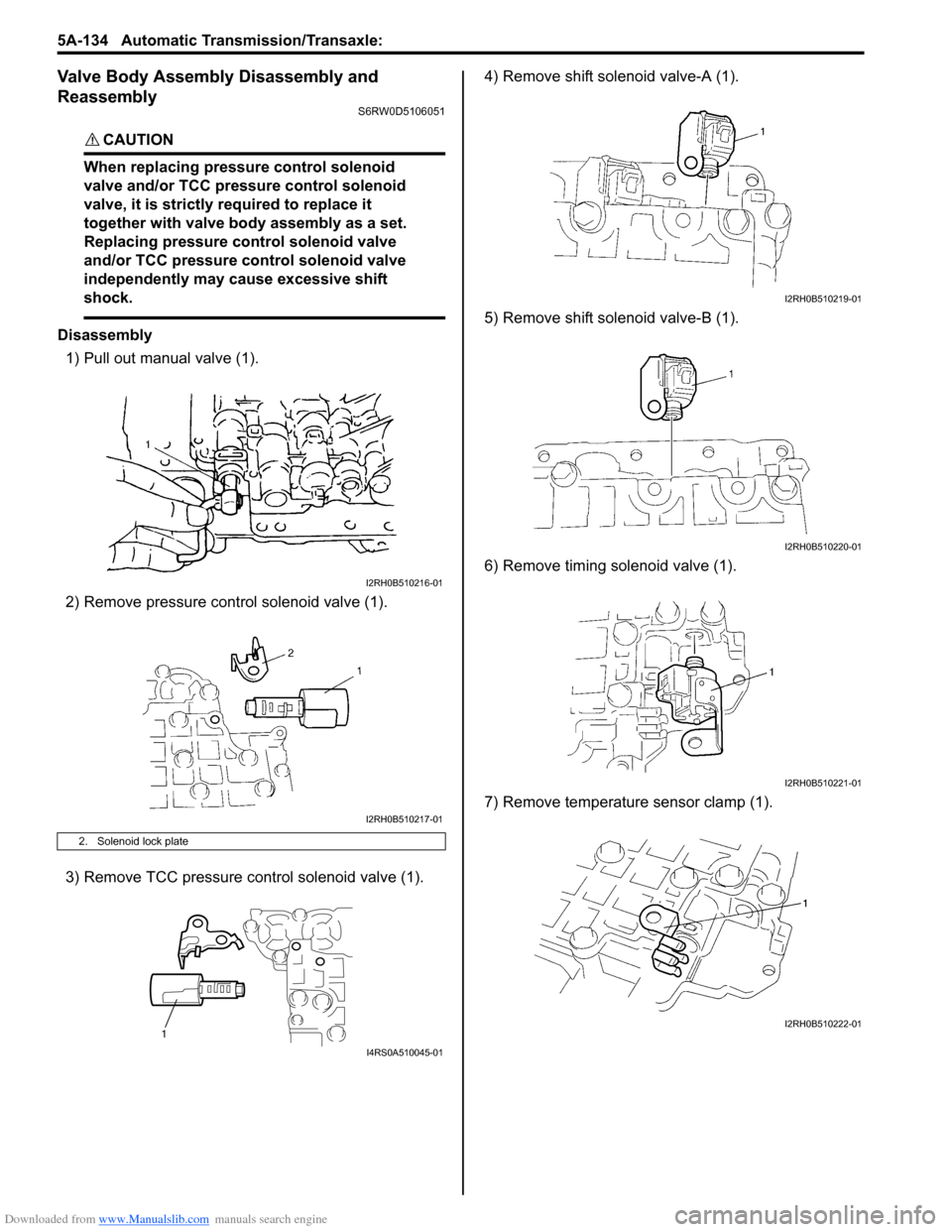
Valve Body Assembly Disassembly and
Reassembly
S6RW0D5106051
CAUTION!
When replacing pressure control solenoid
valve and/or TCC pressure control solenoid
valve, it is strictly required to replace it
together with valve body assembly as a set.
Replacing pressure control solenoid valve
and/or TCC pressure control solenoid valve
independently may cause excessive shift
shock.
Disassembly
1) Pull out manual valve (1).
2) Remove pressure control solenoid valve (1).
3) Remove TCC pressure control solenoid valve (1).4) Remove shift solenoid valve-A (1).
5) Remove shift solenoid valve-B (1).
6) Remove timing solenoid valve (1).
7) Remove temperature sensor clamp (1).
2. Solenoid lock plate
I2RH0B510216-01
I2RH0B510217-01
1
I4RS0A510045-01
I2RH0B510219-01
I2RH0B510220-01
I2RH0B510221-01
I2RH0B510222-01
Page 805 of 1556

Downloaded from www.Manualslib.com manuals search engine Automatic Transmission/Transaxle: 5A-157
72) After applying A/T fluid to new O-ring, fit it to valve
body harness connector (3), then install valve body
harness to transaxle case.
CAUTION!
When put valve body harness (1) into
transaxle case, take care not to damage
transmission fluid temperature sensor (2) at
narrow entrance of case.
Careless sensor treatment might cause
sensor malfunction.
Tightening torque
Valve body harness connector bolt (a): 5.5 N·m (
0.55 kgf-m, 4.0 lb-ft)
73) Install manual valve rod (1) to manual valve lever (3)
and then install valve body assembly (2) to transaxle
case.
74) Tighten valve body bolts to specified torque.
Tightening torque
Valve body bolt: 11 N·m (1.1 kgf-m, 8.0 lb-ft)Valve body bolt length
75) Connect solenoid connectors to solenoid valves
identifying their installing positions by wire colors,
and install transmission fluid temperature sensor to
its clamp.
Solenoid valve coupler specification
I2RH0B510321-01
I2RH0B510322-01
Bolt Length “a” Pieces
A (1) 20 mm (0.79 in.) 6
B (2) 28 mm (1.10 in.) 5
C (3) 49 mm (1.93 in.) 1
D (4) 36 mm (1.42 in.) 1
E (5) 40 mm (1.58 in.) 1
Solenoid valve coupler Wire color
Shift solenoid valve-A (No.1) (1) White
Shift solenoid valve-B (No.2) (2) Black
Timing solenoid valve (3) Yellow
TCC solenoid valve (4)Light green /
Brown
Pressure control solenoid valve (5) Gray / Green
Transmission fluid temperature
sensor (6)Orange
I2RH0B510323-01
1 4
6
3
2
5
I5RW0C510067-02
Page 1244 of 1556

Downloaded from www.Manualslib.com manuals search engine 9A-77 Wiring Systems:
TCM
Lock up
solenoidA/T fluid
temperature
sensorShift
solenoid
No.2Shift
solenoid
No.1
11 12
C1391 2 9
BLK/YELBRNORN
15 4
25
WHT/BLU
Pressure
control
solenoid
LT GRN/BLKGRY
Shift solenoid
LT GRN
ECM
WHTREDWHT/RED
PPL
WHT/RED
BLK/WHT
BLK/RED
BLK/RED
BLK/RED
BLK/WHT
BLK/WHT
5
E371
C343
E371
C34320
E371
C34319
C01
BLKBLKBLK
BLKBLK
E3234E3255
WHT/RED
24 C0625C07717
23116
E012
J/B
15ADOME
37
15AIG COIL
20
15AAT
2
6
3
WHT/BLK
LT GRN/BLK
Timing
solenoid
BLU/BLK
14
WHTBLK
514
2
1C45
Input sensor
C07
WHTBLK
2
1C44
Output sensor
C06
E231
1
3 2
4
YEL/BLU
10AIG1 SIG
26
E32512
BLK
A/T relay
(CAN)
YEL/BLK
7934
E371
C3436
YEL/BLK
Individual circuit
fuse box (No.1)
12
49AB13
50AB
6
16ABBB16
6AB
6
5AB5
4AB4
7AB3
2AB8
6AB10
8AB
A
A
A
B
Weld
splice
M16A
engine
M15A
engine
C312
Weld
splice
C311
BLK/ORN
BLK/ORN
Weld
splice
C313
VSS
1C34
23
"A-5"Main relay
BRM15A engine,
M16A engine
J20A engine A
B
I6RW0C910949-01