Page 480 of 1556

Downloaded from www.Manualslib.com manuals search engine 3A-1 Drive Shaft / Axle: Front
Driveline / Axle
Drive Shaft / Axle
Front
General Description
Front Drive Shaft ConstructionS6RW0D3111001
A constant velocity ball joint is used on the wheel side of both right and left side drive shaft assemblies. For A/T
vehicle, a tripod type constant velocity joint is used on the differential side and center shaft side. For M/T vehicle, a
double offset type constant velocity joint (DOJ) is used on the differential side and center shaft side. The drive shaft
can slide through the tripod joint or the double offset joint (DOJ) in the extension/contraction direction.
Component Location
Front Drive Shaft Assembly Components LocationS6RW0D3113001
I6RW0D311001-01
1. To transaxle 7. Wheel nut : 200 N⋅m (20.0 kgf-m, 145.0 lb-ft)
2. Drive shaft assembly 8. Center shaft assembly (if equipped) : 85 N⋅m (8.5 kgf-m, 61.5 lb-ft)
3. Tie-rod end 9. Center bearing support bolts (if equipped) : 55 N⋅m (5.5 kgf-m, 40.0 lb-ft)
4. Tie-rod end nut 10. Washer : Do not reuse.
5. Ball stud bolt : 45 N⋅m (4.5 kgf-m, 32.5 lb-ft)
6. Drive shaft nut
: After tightening nut to specified torque,
caulk nut securely.:60 N⋅m (6.0 kgf-m, 43.5 lb-ft)
Page 494 of 1556
Downloaded from www.Manualslib.com manuals search engine 3A-15 Drive Shaft / Axle: Rear
Rear
General Description
Rear Drive Shaft ConstructionS6RW0D3121001
Refer to “Front Drive Shaft Construction”.
Repair Instructions
Rear Drive Shaft ComponentsS6RW0D3126001
I5RW0A312001-01
1. Differential side joint (Constant velocity DOJ joint)
: Apply dark gray grease included in spare part to
joint.6. Wheel side joint (Constant velocity ball joint)
: Apply black grease included in spare part to
joint.11. Boot (wheel side)
2. Snap ring 7. Cage : 175 N⋅m (17.5 kgf-m, 126.5 lb-ft)
3. Boot band (Large) 8. Drive shaft nut
: After tightening nut, caulk nut securely.: 80 N⋅m (8.0 kgf-m, 58.0 lb-ft)
4. Boot (Differential side) 9. Rear drive shaft flange nut : Do not reuse.
5. Boot band (Small) 10. Circrip
Page 495 of 1556

Downloaded from www.Manualslib.com manuals search engine Drive Shaft / Axle: Rear 3A-16
Rear Drive Shaft Assembly Removal and
Installation
S6RW0D3126002
Removal
1) Hoist vehicle and remove rear wheel.
2) Undo caulking of drive shaft nut (1) and then remove
drive shaft nut with pull up parking brake lever.
3) Remove rear drive shaft flange nuts (1), and then
remove rear drive shaft.
Installation
Install drive shaft assembly by reversing removal
procedure and noting the following points.
CAUTION!
• Protect boots from any damage,
preventing them from unnecessary contact
while installing drive shaft.
• Do not hit joint boot with hammer.
Inserting joint only by hands is allowed.
• Tighten each nuts to specified torque referring to
“Rear Drive Shaft Components”.
Rear Drive Shaft Disassembly and ReassemblyS6RW0D3126003
Disassembly
Refer to “Front Drive Shaft Disassembly and
Reassembly” note the following point which is different
from the front drive shaft is described.
• Remove differential side boot big band and small
band as follows.
– For boot big band (and small band) without joint [A]:
Remove boot big band (and small band) by tapping
boot and band with plastic hammer. If it is hard to
remove boot big band (and small band), cut it using
a nipper or an iron saw with care not to damage
joint housing.
– For boot big band (and small band) with joint [B]:
Draw hooks of boot big band (and small band)
together and remove band.
1
I5RW0A230023-01
1
I5RW0A312006-02
I5RW0A312003-01
Page 496 of 1556

Downloaded from www.Manualslib.com manuals search engine 3A-17 Drive Shaft / Axle: Rear
Reassembly
Refer to “Front Drive Shaft Disassembly and
Reassembly” note the following points which is different
from the front drive shaft is described.
• Apply grease to each joint.
Grease color
Wheel side: Black
Differential side: Dark gray
Amount
Wheel side: 50 – 70 g (1.8 – 2.5 oz)
Differential side: 70 – 90 g (2.5 – 3.2 oz)
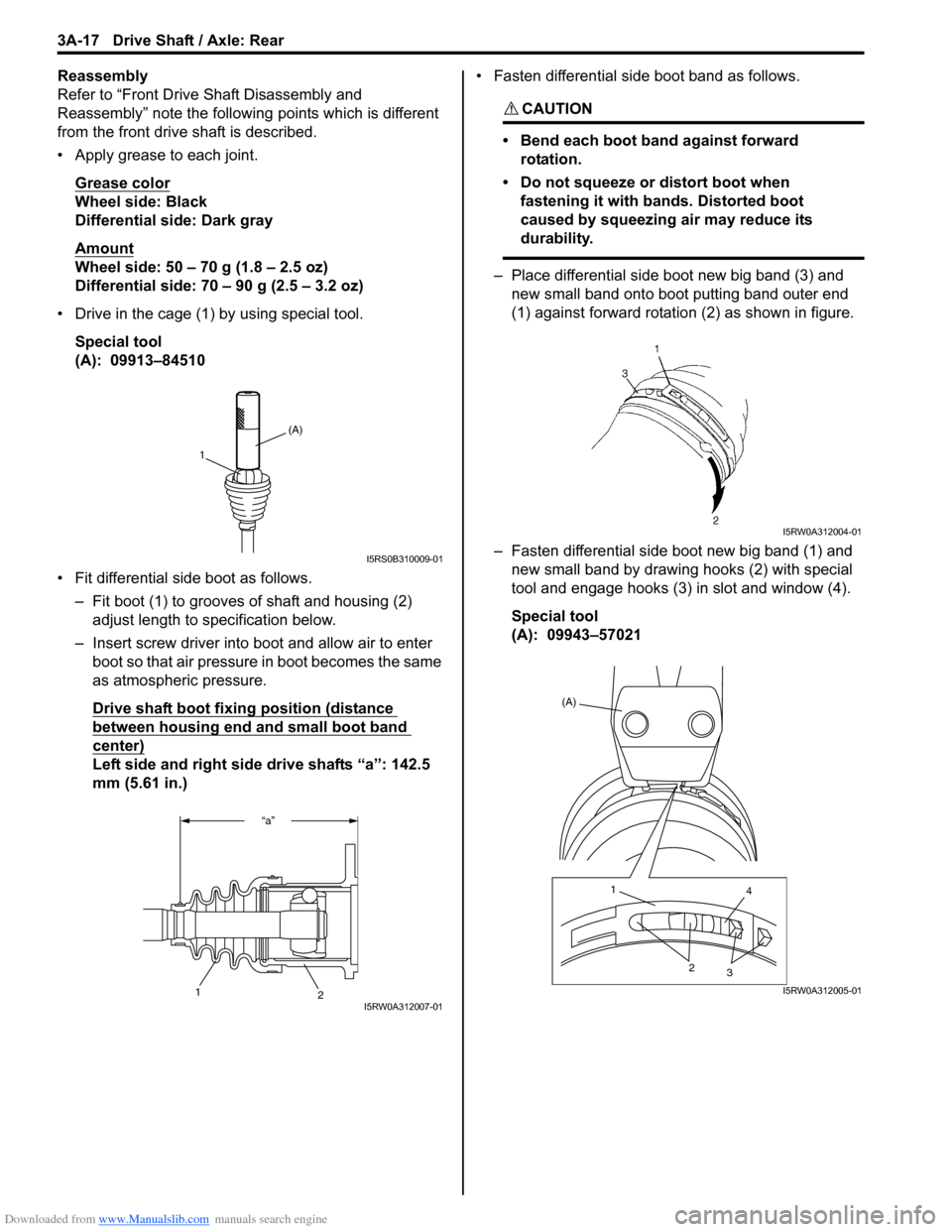
• Drive in the cage (1) by using special tool.
Special tool
(A): 09913–84510
• Fit differential side boot as follows.
– Fit boot (1) to grooves of shaft and housing (2)
adjust length to specification below.
– Insert screw driver into boot and allow air to enter
boot so that air pressure in boot becomes the same
as atmospheric pressure.
Drive shaft boot fixing position (distance
between housing end and small boot band
center)
Left side and right side drive shafts “a”: 142.5
mm (5.61 in.)• Fasten differential side boot band as follows.
CAUTION!
• Bend each boot band against forward
rotation.
• Do not squeeze or distort boot when
fastening it with bands. Distorted boot
caused by squeezing air may reduce its
durability.
– Place differential side boot new big band (3) and
new small band onto boot putting band outer end
(1) against forward rotation (2) as shown in figure.
– Fasten differential side boot new big band (1) and
new small band by drawing hooks (2) with special
tool and engage hooks (3) in slot and window (4).
Special tool
(A): 09943–57021
(A)
1
I5RS0B310009-01
“a”
2
1I5RW0A312007-01
I5RW0A312004-01
(A)
1
4
2
3
I5RW0A312005-01
Page 498 of 1556

Downloaded from www.Manualslib.com manuals search engine 3B-1 Differential:
Driveline / Axle
Differential
Precautions
Precaution for Rear Differential Oil LeakageS6RW0D3200001
Whenever vehicle is hoisted for any other service work than oil change, also be sure to check for oil leakage.
Precautions in Diagnosing TroubleS6RW0D3200002
• Do not disconnect the following parts before confirming diagnostic information (DTC, etc.) stored in 4WD control
module memory. These actions will erase memorized information in 4WD control module memory.
– Disconnection of coupler from 4WD control module
– Disconnection of battery cable from battery
– Disconnection of ground wire harness of 4WD control module
– Disconnect main fuse from fuse box
• Diagnostic information stored in 4WD control module memory can be cleared as well as checked by using SUZUKI
scan tool. Before using scan tool, read its Operator’s (Instruction) Manual carefully to have good understanding as
to what functions are available and how to use it.
• Be sure to read “Precautions for Electrical Circuit Service:” before inspection and observe what is written there.
Page 499 of 1556

Downloaded from www.Manualslib.com manuals search engine Differential: 3B-2
General Description
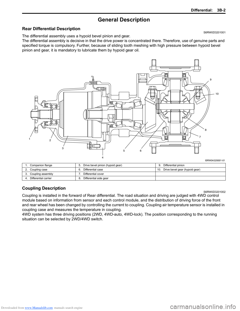
Rear Differential DescriptionS6RW0D3201001
The differential assembly uses a hypoid bevel pinion and gear.
The differential assembly is decisive in that the drive power is concentrated there. Therefore, use of genuine parts and
specified torque is compulsory. Further, because of sliding tooth meshing with high pressure between hypoid bevel
pinion and gear, it is mandatory to lubricate them by hypoid gear oil.
Coupling DescriptionS6RW0D3201002
Coupling is installed in the forward of Rear differential. The road situation and driving are judged with 4WD control
module based on information from sensor and each control module, and the distribution of driving force of the front
and rear wheel has been changed by controlling the current to coupling. Coupling air temperature sensor is installed in
coupling case and measures the temperature in coupling.
4WD system has three driving positions (2WD, 4WD-auto, 4WD-lock). The position corresponding to the running
situation can be selected by 2WD/4WD switch.
1
2
3
4567810 9
I5RW0A320001-01
1. Companion flange 5. Drive bevel pinion (hypoid gear) 9. Differential pinion
2. Coupling case 6. Differential case 10. Drive bevel gear (hypoid gear)
3. Coupling assembly 7. Differential cover
4. Differential carrier 8. Differential side gear
Page 500 of 1556
Downloaded from www.Manualslib.com manuals search engine 3B-3 Differential:
4WD Control System ComponentsS6RW0D3201003
2
1
3
6
5 4
I5RW0A320002-04
1. 4WD control module 3. 4WD LOCK indicator 5. Coupling assembly
2. 4WD AUTO indicator 4. 2WD/4WD switch 6. Coupling air temperature sensor
Page 502 of 1556

Downloaded from www.Manualslib.com manuals search engine 3B-5 Differential:
4WD Control System Wiring Circuit DiagramS6RW0D3201006
Terminal Arrangement of 4WD Control ModuleS6RW0D3201007
5V
5V
12V
G26-3
YEL
GRY
G26-2
G26-22G26-23REDWHT
G26-13
G26-14
G26-12
G26-11
G26-10BLK
WHT/RED
RED/BLK
GRY/YEL
RED/WHT
12V
L102-1
L102-4
1
37
9
10
12
13
14
12V
G26-21BLU
G26-25
G26-24ORN
BRN
5V
28
11
WHT
WHT
WHTWHTWHTWHT
WHT
RED
RED
RED
REDRED
RED
RED
46
5
L174-4BLK/ORNL174-5L174-1
I7RW01320001-01
1. Coupling assembly 6. ECM 11. Data link connector (DLC)
2. Coupling air temperature sensor 7. 4WD control module 12. “IG COIL” fuse
3. Combination meter 8. 2WD/4WD switch 13. “4WD” fuse
4. BCM 9. “4WD” switch 14. Main fuse box
5. ABS / ESP® control module 10. “4WD lock” switch
1 2 3 4 5 6 7 8 9 10 11 12
13 14 15 16 17 18 19 20 21 22 23 24 25 26
[A]
I4JA01332038-01
[A]: Connector “G26” viewed from harness side
Te r m i n a l C i r c u i t Te r m i n a l C i r c u i t
G26-2 Coupling assembly (power) G26-14 “4WD lock” switch
G26-3 Coupling assembly (ground) G26-21 Data link connector (DLC)
G26-10 Ground G26-22 CAN communication line (high)
G26-11 Power source for internal memory G26-23 CAN communication line (low)
G26-12 Power source G26-24 Coupling air temperature sensor (ground)
G26-13 “4WD” switch G26-25 Coupling air temperature sensor (power)