Page 299 of 2896
AT-286
REPAIR FOR COMPONENT PARTS
Revision: June 20062007 Versa
3. Pull out retaining pin (2) of parking rod plate (1) using nippers.
4. Pull out retaining pin (1) of manual shaft using nippers.
5. Remove parking rod plate (with parking rod) (3) from manual
shaft (1).
6. Remove parking rod from parking rod plate (3).
7. Remove manual plate (2) from manual shaft (1).
8. Draw out manual shaft (1) from transaxle case.
9. Remove manual shaft oil seal from transaxle case using a flat-
bladed screwdriver.
CAUTION:
Be careful not to scratch transaxle case.
INSPECTION
Check component parts, and replace if damaged or worn.
SCIA5806J
SCIA6514J
SCIA7005E
SAT0 8 0D
Page 304 of 2896

REPAIR FOR COMPONENT PARTS
AT-291
D
E
F
G
H
I
J
K
L
MA
B
AT
Revision: June 20062007 Versa
INSPECTION
Oil Pump Housing, Oil Pump Cover, Inner Gear and Outer Gear
Check for wear or damage. Replace if necessary.
Side Clearances
�Measure side clearance of inner gear and outer gear in at least
four places around each outside edge. Clearances measured
values should be within the specified clearance.
�If clearance is less than standard, select inner gear and outer
gear as a set so that clearance is within specifications. Refer to
“Parts Information” for the inner gear and outer gear selection.
�If clearance is more than standard, replace whole oil pump
assembly except oil pump cover.
�Measure clearance between outer gear and oil pump housing.
�If not within allowable limit, replace whole oil pump assembly
except oil pump cover.
Seal Ring Clearance
�Measure clearance between seal ring and ring groove.
�If not within allowable limit, replace oil pump cover assembly.Standard clearance: Refer to AT- 3 8 2 , "
Oil Pump" .
SCIA4957E
Standard clearance and allowable limit:
Refer to AT-382, "
Oil Pump" .
SAT0 9 6D
Standard clearance and allowable limit:
Refer to AT-382, "
Oil Pump" .
SAT0 9 7D
Page 306 of 2896
REPAIR FOR COMPONENT PARTS
AT-293
D
E
F
G
H
I
J
K
L
MA
B
AT
Revision: June 20062007 Versa
Control Valve AssemblyUCS005W 5
COMPONENTS
1. Pilot filter 2. Control valve upper body 3. Steel ball
4. Separating plate 5. Control valve inter body 6. Steel ball
7. Support plate 8. Separating plate 9. Control valve lower body
10. Line pressure relief valve spring 11. Check ball 12. Torque converter pressure holding
spring
13. Solenoid valve assembly 14. Terminal body 15. O-ring
16. O-ring 17. O-ring 18. Oil strainer
Refer to GI section to make sure icons (symbol marks) in the figure. Refer to GI-10, "
Components" .
SCIA5967J
Page 310 of 2896

REPAIR FOR COMPONENT PARTS
AT-297
D
E
F
G
H
I
J
K
L
MA
B
AT
Revision: June 20062007 Versa
INSPECTION
Control Valve Lower and Upper Bodies
CAUTION:
Be careful not to lose these parts.
�Check to see that retainer plates are properly positioned in con-
trol valve lower body.
�Check to see that retainer plates are properly positioned in con-
trol valve upper body.
Oil Strainer
Check wire netting of oil strainer for damage. Replace if necessary.
Shift Solenoid Valves “A” and “B”, Line Pressure Solenoid Valve, Torque Converter Clutch
Solenoid Valve and Overrun Clutch Solenoid Valve
Measure resistance.
�For shift solenoid valve A, refer to AT-155, "Component Inspec-
tion" .
�For shift solenoid valve B, refer to AT-160, "Component Inspec-
tion" .
�For line pressure solenoid valve, refer to AT-150, "Component
Inspection" .
�For torque converter clutch solenoid valve, refer to AT-138,
"Component Inspection" .
�For overrun clutch solenoid valve, refer to AT-165, "Component
Inspection" .
A/T Fluid Temperature Sensor
Measure resistance.
SCIA4978E
SCIA4979E
SCIA3291E
SCIA3485E
Page 311 of 2896
AT-298
REPAIR FOR COMPONENT PARTS
Revision: June 20062007 Versa
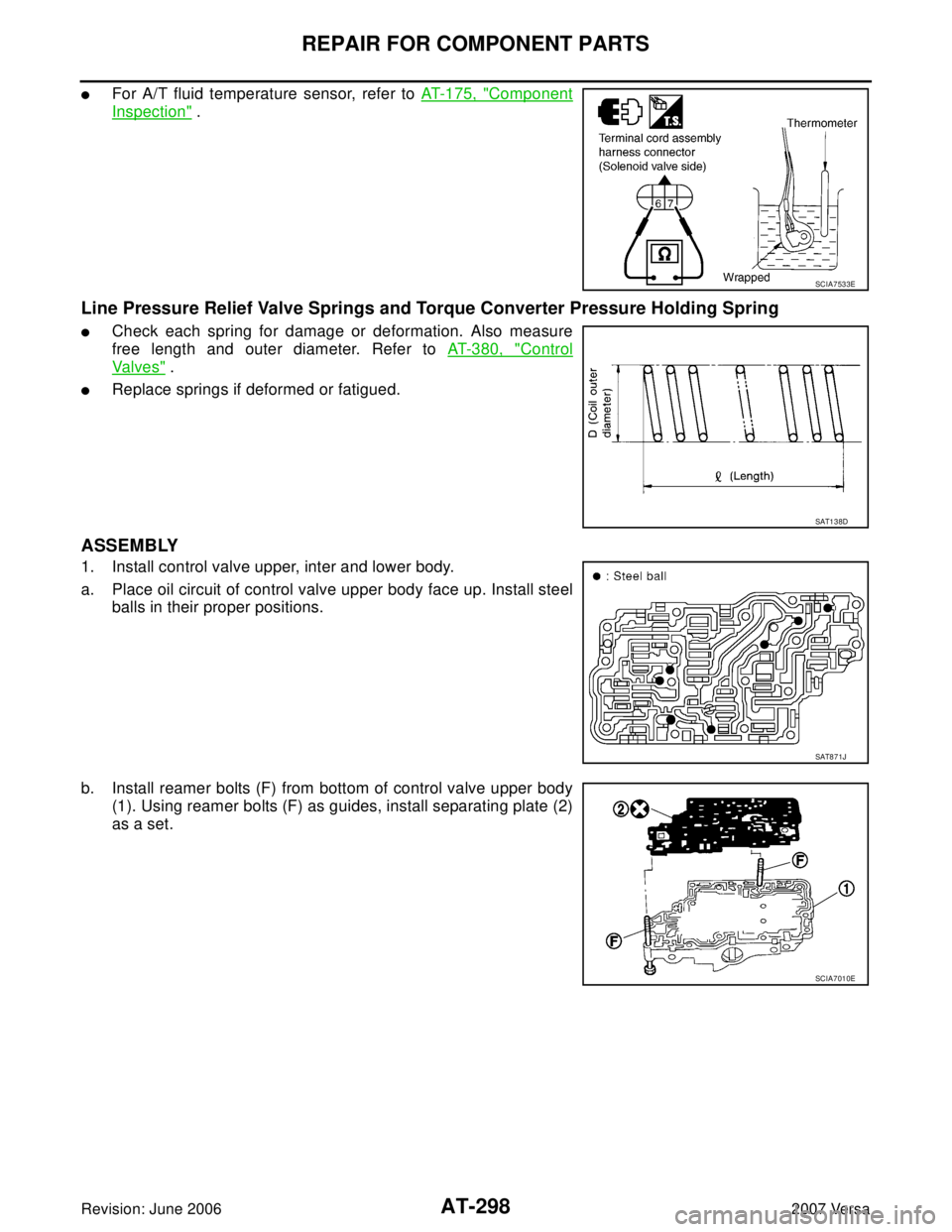
�For A/T fluid temperature sensor, refer to AT-175, "Component
Inspection" .
Line Pressure Relief Valve Springs and Torque Converter Pressure Holding Spring
�Check each spring for damage or deformation. Also measure
free length and outer diameter. Refer to AT-380, "
Control
Va l v e s" .
�Replace springs if deformed or fatigued.
ASSEMBLY
1. Install control valve upper, inter and lower body.
a. Place oil circuit of control valve upper body face up. Install steel
balls in their proper positions.
b. Install reamer bolts (F) from bottom of control valve upper body
(1). Using reamer bolts (F) as guides, install separating plate (2)
as a set.
SCIA7533E
SAT1 3 8D
SAT8 7 1J
SCIA7010E
Page 322 of 2896

REPAIR FOR COMPONENT PARTS
AT-309
D
E
F
G
H
I
J
K
L
MA
B
AT
Revision: June 20062007 Versa
Reverse ClutchUCS005W 8
COMPONENTS
DISASSEMBLY
1. Check operation of reverse clutch
a. Install seal rings to drum support of oil pump assembly, and set reverse clutch assembly.
b. Apply compressed air into the oil hole at the location as shown
in the figure.
c. Check to see that retaining plate moves to snap ring.
d. If retaining plate does not contact snap ring:
�D-ring might be damaged.
�Seal lip might be damaged.
�Fluid might be leaking past piston check ball.
2. Remove snap ring (1) using a flat-bladed screwdriver A.
3. Remove retaining plate, drive plates, driven plates and dish
plates.
1. Reverse clutch drum 2. D-ring 3. Seal lip
4. Reverse clutch piston 5. Spring retainer assembly 6. Snap ring
7. Dish plate 8. Driven plate 9. Retaining plate
10. Snap ring 11. Drive plate
Refer to GI section to make sure icons (symbol marks) in the figure. Refer to GI-10, "
Components" .
SCIA6939J
SAT1 5 5D
SCIA7024J
Page 324 of 2896

REPAIR FOR COMPONENT PARTS
AT-311
D
E
F
G
H
I
J
K
L
MA
B
AT
Revision: June 20062007 Versa
INSPECTION
Reverse Clutch Snap Ring
Check for deformation, fatigue or damage. Replace if necessary.
Reverse Clutch Drive Plates
�Check facing for burns, cracks or damage. Replace if necessary.
�Measure thickness of facing.
CAUTION:
�Measure the thickness at 3 locations and find the aver-
age.
�Inspect all drive plates.
�Replace if the thickness is below the allowable limit.
Reverse Clutch Dish Plates
�Check for deformation or damage.
�Measure thickness (t) of dish plate. Replace if damaged,
deformed or worn.
Reverse Clutch Spring Retainer Assembly
Measure length (L) of spring retainer assembly. Replace if damaged,
deformed or worn.
CAUTION:
Do not remove return springs (A) from spring retainer (B)
Reverse Clutch Piston
�Make sure that check balls are not fixed.
�Apply compressed air to check ball oil hole opposite from return
spring. Make sure there is no air leakage.
�Apply compressed air to oil hole on return spring side to make
sure that air leaks past ball.
Reverse Clutch Drum
Check for deformation or damage. Replace if necessary.Thickness of drive plate
Standard and allowable limit:
Refer to AT-380, "
REVERSE CLUTCH" .
SAT1 6 2D
Thickness of dish plate (t): 2.87 mm (0.1130 in)
SCIA8008E
Length (L): 20.1 mm (0.791 in)
SCIA7025J
SAT1 6 4D
Page 327 of 2896
AT-314
REPAIR FOR COMPONENT PARTS
Revision: June 20062007 Versa
High ClutchUCS005W9
COMPONENTS
DISASSEMBLY
1. Check operation of high clutch.
a. Apply compressed air into the oil hole (A) of input shaft assem-
bly (high clutch drum) at the location as shown in the figure.
CAUTION:
Block the oil hole (A) on the opposite side with lint-free
cloth B.
b. Check to see that retaining plate moves to snap ring.
c. If retaining plate does not contact snap ring:
�High clutch piston seal might be damaged.
2. Remove seal rings from input shaft assembly (high clutch drum).
1. Seal ring 2. Driven plate 3. Retaining plate
4. Snap ring 5. Drive plate 6. Snap ring
7. Cancel cover 8. Spring retainer assembly 9. High clutch Piston
10. Input shaft assembly (high clutch
drum)
SCIA6741E
SCIA7032E
SCIA4890E
 of parking rod plate (1) using nippers.
4. Pull out retaining pin (1) of manual shaft using nippers.
5. Re")

 of input sha")