Page 333 of 2896

AT-320
REPAIR FOR COMPONENT PARTS
Revision: June 20062007 Versa
Forward and Overrun ClutchesUCS005WA
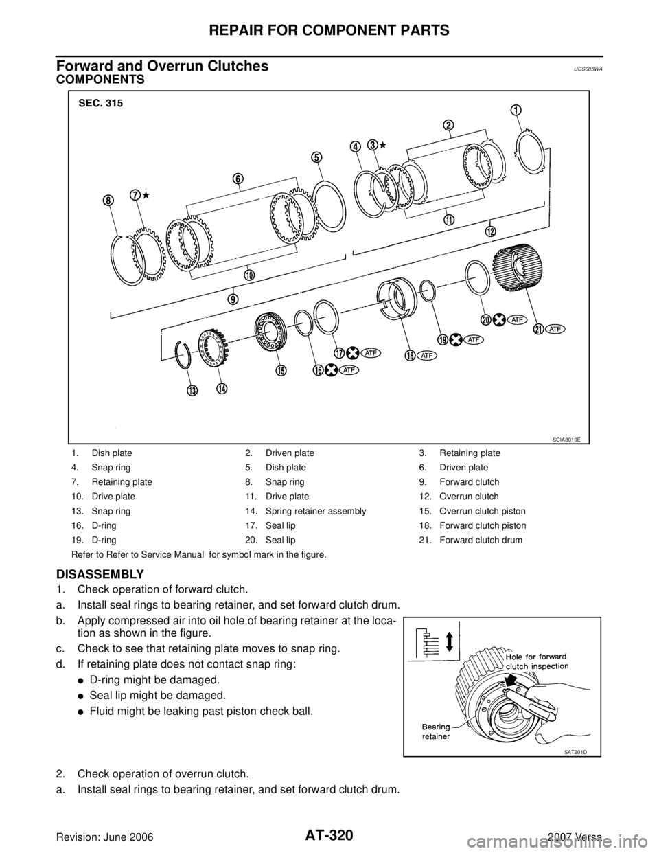
COMPONENTS
DISASSEMBLY
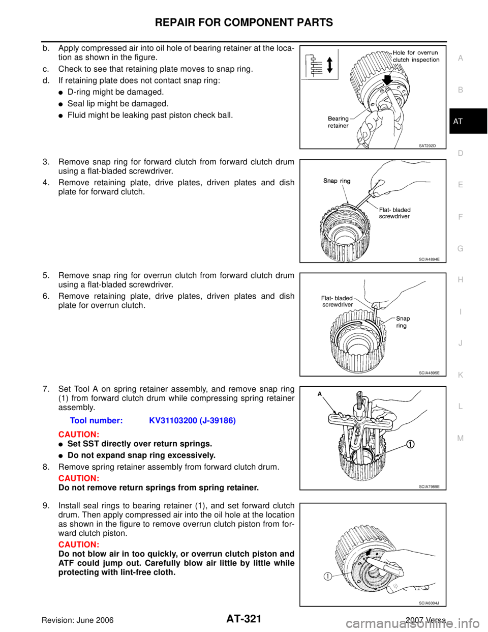
1. Check operation of forward clutch.
a. Install seal rings to bearing retainer, and set forward clutch drum.
b. Apply compressed air into oil hole of bearing retainer at the loca-
tion as shown in the figure.
c. Check to see that retaining plate moves to snap ring.
d. If retaining plate does not contact snap ring:
�D-ring might be damaged.
�Seal lip might be damaged.
�Fluid might be leaking past piston check ball.
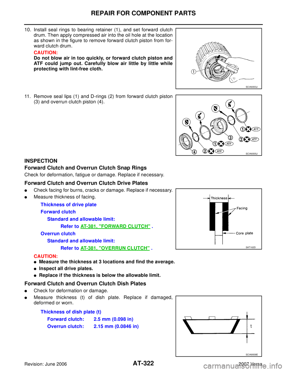
2. Check operation of overrun clutch.
a. Install seal rings to bearing retainer, and set forward clutch drum.
1. Dish plate 2. Driven plate 3. Retaining plate
4. Snap ring 5. Dish plate 6. Driven plate
7. Retaining plate 8. Snap ring 9. Forward clutch
10. Drive plate 11. Drive plate 12. Overrun clutch
13. Snap ring 14. Spring retainer assembly 15. Overrun clutch piston
16. D-ring 17. Seal lip 18. Forward clutch piston
19. D-ring 20. Seal lip 21. Forward clutch drum
Refer to Refer to Service Manual for symbol mark in the figure.
SCIA8010E
SAT2 0 1D
Page 334 of 2896

REPAIR FOR COMPONENT PARTS
AT-321
D
E
F
G
H
I
J
K
L
MA
B
AT
Revision: June 20062007 Versa
b. Apply compressed air into oil hole of bearing retainer at the loca-
tion as shown in the figure.
c. Check to see that retaining plate moves to snap ring.
d. If retaining plate does not contact snap ring:
�D-ring might be damaged.
�Seal lip might be damaged.
�Fluid might be leaking past piston check ball.
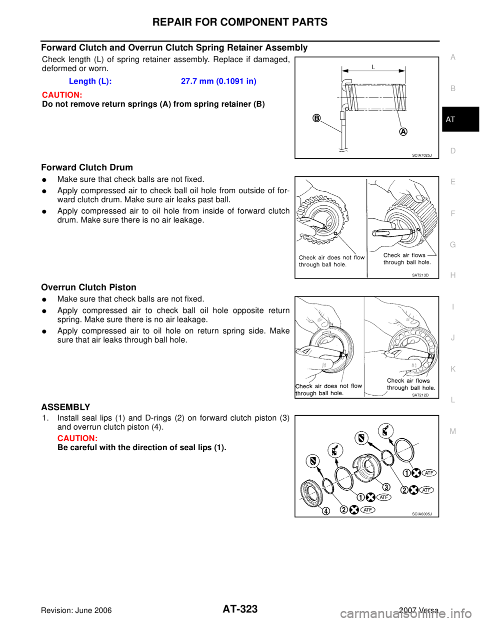
3. Remove snap ring for forward clutch from forward clutch drum
using a flat-bladed screwdriver.
4. Remove retaining plate, drive plates, driven plates and dish
plate for forward clutch.
5. Remove snap ring for overrun clutch from forward clutch drum
using a flat-bladed screwdriver.
6. Remove retaining plate, drive plates, driven plates and dish
plate for overrun clutch.
7. Set Tool A on spring retainer assembly, and remove snap ring
(1) from forward clutch drum while compressing spring retainer
assembly.
CAUTION:
�Set SST directly over return springs.
�Do not expand snap ring excessively.
8. Remove spring retainer assembly from forward clutch drum.
CAUTION:
Do not remove return springs from spring retainer.
9. Install seal rings to bearing retainer (1), and set forward clutch
drum. Then apply compressed air into the oil hole at the location
as shown in the figure to remove overrun clutch piston from for-
ward clutch piston.
CAUTION:
Do not blow air in too quickly, or overrun clutch piston and
ATF could jump out. Carefully blow air little by little while
protecting with lint-free cloth.
SAT2 0 2D
SCIA4894E
SCIA4895E
Tool number: KV31103200 (J-39186)
SCIA7989E
SCIA6004J
Page 335 of 2896

AT-322
REPAIR FOR COMPONENT PARTS
Revision: June 20062007 Versa
10. Install seal rings to bearing retainer (1), and set forward clutch
drum. Then apply compressed air into the oil hole at the location
as shown in the figure to remove forward clutch piston from for-
ward clutch drum.
CAUTION:
Do not blow air in too quickly, or forward clutch piston and
ATF could jump out. Carefully blow air little by little while
protecting with lint-free cloth.
11. Remove seal lips (1) and D-rings (2) from forward clutch piston
(3) and overrun clutch piston (4).
INSPECTION
Forward Clutch and Overrun Clutch Snap Rings
Check for deformation, fatigue or damage. Replace if necessary.
Forward Clutch and Overrun Clutch Drive Plates
�Check facing for burns, cracks or damage. Replace if necessary.
�Measure thickness of facing.
CAUTION:
�Measure the thickness at 3 locations and find the average.
�Inspect all drive plates.
�Replace if the thickness is below the allowable limit.
Forward Clutch and Overrun Clutch Dish Plates
�Check for deformation or damage.
�Measure thickness (t) of dish plate. Replace if damaged,
deformed or worn.
SCIA6003J
SCIA6005J
Thickness of drive plate
Forward clutch
Standard and allowable limit:
Refer to AT-381, "
FORWARD CLUTCH" .
Overrun clutch
Standard and allowable limit:
Refer to AT-381, "
OVERRUN CLUTCH" .SAT1 6 2D
Thickness of dish plate (t)
Forward clutch: 2.5 mm (0.098 in)
Overrun clutch: 2.15 mm (0.0846 in)
SCIA8008E
Page 336 of 2896

REPAIR FOR COMPONENT PARTS
AT-323
D
E
F
G
H
I
J
K
L
MA
B
AT
Revision: June 20062007 Versa
Forward Clutch and Overrun Clutch Spring Retainer Assembly
Check length (L) of spring retainer assembly. Replace if damaged,
deformed or worn.
CAUTION:
Do not remove return springs (A) from spring retainer (B)
Forward Clutch Drum
�Make sure that check balls are not fixed.
�Apply compressed air to check ball oil hole from outside of for-
ward clutch drum. Make sure air leaks past ball.
�Apply compressed air to oil hole from inside of forward clutch
drum. Make sure there is no air leakage.
Overrun Clutch Piston
�Make sure that check balls are not fixed.
�Apply compressed air to check ball oil hole opposite return
spring. Make sure there is no air leakage.
�Apply compressed air to oil hole on return spring side. Make
sure that air leaks through ball hole.
ASSEMBLY
1. Install seal lips (1) and D-rings (2) on forward clutch piston (3)
and overrun clutch piston (4).
CAUTION:
Be careful with the direction of seal lips (1).Length (L): 27.7 mm (0.1091 in)
SCIA7025J
SAT2 1 3D
SAT2 1 2D
SCIA6005J
Page 340 of 2896
REPAIR FOR COMPONENT PARTS
AT-327
D
E
F
G
H
I
J
K
L
MA
B
AT
Revision: June 20062007 Versa
Low & Reverse BrakeUCS005WB
COMPONENTS
DISASSEMBLY
1. Check operation of low & reverse brake.
a. Apply compressed air into oil hole of transaxle case at the loca-
tion as shown in the figure.
b. Check to see that retaining plate moves to snap ring.
c. If retaining plate does not contact snap ring:
�D-ring might be damaged.
�Seal lip might be damaged.
2. Remove snap ring (1) using a flat-bladed screwdriver A.
3. Remove retaining plates, drive plates, driven plates, dish plates.
1. Seal lip 2. D-ring 3. Low & reverse brake piston
4. Spring retainer assembly 5. Snap ring 6. Driven plate
7. Retaining plate 8. Driven plate 9. Retaining plate
10. Snap ring 11. Drive plate 12. Dish plate
Refer to GI section to make sure icons (symbol marks) in the figure. Refer to GI-10, "
Components" .
SCIA6007J
SAT2 3 0D
SCIA7039E
Page 384 of 2896
ASSEMBLY
AT-371
D
E
F
G
H
I
J
K
L
MA
B
AT
Revision: June 20062007 Versa
13. Adjust brake band.
a. Tighten anchor end pin to the specified torque.
b. Back off anchor end pin two and a half turns.
c. Tighten lock nut while holding anchor end pin. Refer to AT-257,
"Components" .
14. Apply compressed air into oil holes of transaxle case and check
operation of brake band.
15. Install final drive assembly on transaxle case.:4.9 N·m (0.50 kg-m, 43 in-lb)
SAT3 9 4D
SAT3 9 5D
SAT3 9 6D
SAT3 9 7D
SAT2 2 8F
Page 421 of 2896

AV-24
AUDIO
Revision: June 20062007 Versa
NOTE:
The source of the noise can be found easily by listening to the noise while removing the fuses of electrical
components, one by one.
TYPE OF NOISE AND POSSIBLE CAUSE
Power Supply Circuit InspectionEKS00I9U
1. CHECK FUSE
Check that the following fuses of the subwoofer (premium system) and audio unit are not blown.
OK or NG
OK >> GO TO 2.
NG >> If fuse is blown, be sure to eliminate cause of blown fuse before installing new fuse. Refer to PG-
4, "POWER SUPPLY ROUTING CIRCUIT" .
2. AUDIO UNIT POWER SUPPLY CIRCUIT CHECK
1. Disconnect audio unit connector.
2. Check voltage between the audio unit and ground.
OK or NG
OK >> With premium system, GO TO 3.
NG >>
�Check connector housings for disconnected or loose
terminals.
�Repair harness or connector.
Occurrence condition Possible cause
Occurs only when engine is ON.A continuous growling noise occurs. The speed of
the noise varies with changes in the engine speed.Ignition components
A whistling noise occurs while the engine speed is
high. A booming noise occurs while the engine is
running and the lighting switch is ON.Generator
Noise only occurs when various
electrical components are oper-
ating.A cracking or snapping sound occurs with the
operation of various switches.Relay malfunction, radio malfunction
The noise occurs when various motors are operat-
ing.
�Motor case ground
�Motor
The noise occurs constantly, not just under certain conditions.
�Rear defogger coil malfunction
�Open circuit in printed heater
A cracking or snapping sound occurs while the vehicle is being driven, especially
when it is vibrating excessively.
�Ground wire of body parts.
�Ground due to improper part installation
�Wiring connections or a short circuit
Unit Terminals Signal name Fuse No.
Audio unit19 Battery power 27
7 Ignition switch ACC or ON 20
Subwoofer (with premium audio) 1 Ignition switch ACC or ON 27
UnitTe r m i n a l N o .
OFF ACC ON (+)
(-)
Connector Terminal
Audio unit M4319 GroundBattery
voltageBattery
voltageBattery
voltage
7 Ground 0VBattery
voltageBattery
voltage
WKIA5345E
Page 481 of 2896

BCS-18
BCM (BODY CONTROL MODULE)
Revision: June 20062007 Versa
WORK SUPPORT
Display Item List
CAN Communication Inspection Using CONSULT-II (Self-Diagnosis)EKS00I88
1. SELF-DIAGNOSTIC RESULT CHECK
NOTE:
If CONSULT-II is used with no connection of CONSULT-II CONVERTER, malfunctions might be detected in
self-diagnosis depending on control unit which carries out CAN communication.
1. Connect CONSULT–II and CONSULT-II CONVERTER, and select “BCM” on “SELECT SYSTEM” screen.
2. Select “BCM” on “SELECT TEST ITEM” screen, and select “SELF-DIAG RESULTS”.
3. Check display content in self-diagnostic results.
Contents displayed
No malfunction>>Inspection End
Malfunction in CAN communication system>>After printing the monitor items, go to “CAN System”. Refer to
LAN-7, "
TROUBLE DIAGNOSIS" .
Oil pressure switch SIGNAL BUFFER××
Low tire pressure mon-
itorAIR PRESSURE
MONITOR×× × ×
Panic alarm PANIC ALARM× System and itemCONSULT-II dis-
playDiagnostic test mode (Inspection by part)
WORK
SUPPORTSELF−
DIAG
RESULTSCAN DIAG
SUPPORT
MNTRDATA
MONITORECU
PA R T
NUMBERACTIVE
TESTCON-
FIGU-
RATION
Item Description
RESET SETTING VALUE Return a value set with WORK SUPPORT of each system to a default value in factory shipment.
CONSULT-II display code Diagnosis item
U1000INITIAL DIAG
TRANSMIT DIAG
ECM
IPDM E/R
METER/M&A
I-KEY