Page 2298 of 2896
LT-90
INTERIOR LAMP
Revision: June 20062007 Versa
Luggage Compartment LampEKS00HZI
BULB REPLACEMENT
1. Remove luggage compartment lamp cover.
2. Press tab A and remove the bulb.
3. Installation is in the reverse order of removal.
REMOVAL AND INSTALLATION
Removal
1. Remove luggage compartment lamp from the luggage side finisher LH.
2. Disconnect luggage compartment lamp connector.
Installation
Installation is in the reverse order of removal.
1. Luggage compartment lamp bulb cover 2. Luggage compartment lamp A. Tab A
LKIA0761E
Page 2312 of 2896

LT-104
INTERIOR ROOM LAMP
Revision: June 20062007 Versa
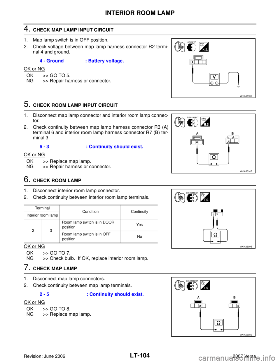
4. CHECK MAP LAMP INPUT CIRCUIT
1. Map lamp switch is in OFF position.
2. Check voltage between map lamp harness connector R2 termi-
nal 4 and ground.
OK or NG
OK >> GO TO 5.
NG >> Repair harness or connector.
5. CHECK ROOM LAMP INPUT CIRCUIT
1. Disconnect map lamp connector and interior room lamp connec-
tor.
2. Check continuity between map lamp harness connector R3 (A)
terminal 6 and interior room lamp harness connector R7 (B) ter-
minal 3.
OK or NG
OK >> Replace map lamp.
NG >> Repair harness or connector.
6. CHECK ROOM LAMP
1. Disconnect interior room lamp connector.
2. Check continuity between interior room lamp terminals.
OK or NG
OK >> GO TO 7.
NG >> Check bulb. If OK, replace interior room lamp.
7. CHECK MAP LAMP
1. Disconnect map lamp connectors.
2. Check continuity between map lamp terminals.
OK or NG
OK >> GO TO 8.
NG >> Replace map lamp.4 - Ground : Battery voltage.
WKIA5513E
6 - 3 : Continuity should exist.
WKIA5514E
Te r m i n a l
Condition Continuity
Interior room lamp
23Room lamp switch is in DOOR
positionYe s
Room lamp switch is in OFF
positionNo
WKIA5609E
2 - 5 : Continuity should exist.
WKIA5608E
Page 2314 of 2896

LT-106
INTERIOR ROOM LAMP
Revision: June 20062007 Versa
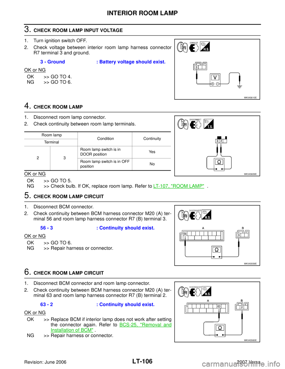
3. CHECK ROOM LAMP INPUT VOLTAGE
1. Turn ignition switch OFF.
2. Check voltage between interior room lamp harness connector
R7 terminal 3 and ground.
OK or NG
OK >> GO TO 4.
NG >> GO TO 6.
4. CHECK ROOM LAMP
1. Disconnect room lamp connector.
2. Check continuity between room lamp terminals.
OK or NG
OK >> GO TO 5.
NG >> Check bulb. If OK, replace room lamp. Refer to LT-107, "
ROOM LAMP" .
5. CHECK ROOM LAMP CIRCUIT
1. Disconnect BCM connector.
2. Check continuity between BCM harness connector M20 (A) ter-
minal 56 and room lamp harness connector R7 (B) terminal 3.
OK or NG
OK >> GO TO 6.
NG >> Repair harness or connector.
6. CHECK ROOM LAMP CIRCUIT
1. Disconnect BCM connector and room lamp connector.
2. Check continuity between BCM harness connector M20 (A) ter-
minal 63 and room lamp harness connector R7 (B) terminal 2.
OK or NG
OK >> Replace BCM if interior lamp does not work after setting
the connector again. Refer to BCS-25, "
Removal and
Installation of BCM" .
NG >> Repair harness or connector.3 - Ground : Battery voltage should exist.
WKIA5610E
Room lamp
Condition Continuity
Te r m i n a l
23 Room lamp switch is in
DOOR positionYe s
Room lamp switch is in OFF
positionNo
WKIA5609E
56 - 3 : Continuity should exist.
WKIA5559E
63 - 2 : Continuity should exist.
WKIA5560E
Page 2315 of 2896
INTERIOR ROOM LAMP
LT-107
C
D
E
F
G
H
I
J
L
MA
B
LT
Revision: June 20062007 Versa
Bulb ReplacementEKS00HZS
ROOM LAMP
1. Remove lens (1) by inserting suitable tool and releasing LH
(switch side first).
2. Remove bulb (2).
3. Installation is in the reverse order of removal.
NOTE:
Insert the lens hook end RH side first to install lens.
Removal and InstallationEKS00HZT
ROOM LAMP
Removal
1. Remove lens (1) and remove the room lamp by pulling down to
release the room lamp metal clips (A).
2. Disconnect connector and remove room lamp.
Installation
Installation is in the reverse order of removal.
PKIC1048E
PKIC1049E
Page 2323 of 2896
ILLUMINATION
LT-115
C
D
E
F
G
H
I
J
L
MA
B
LT
Revision: June 20062007 Versa
Bulb ReplacementEKS00HZZ
GLOVE BOX LAMP
1. Remove glove box assembly. Refer to IP-10, "INSTRUMENT PANEL ASSEMBLY" .
2. Turn bulb socket (1) counterclockwise and remove it.
3. Remove bulb (2).
PKIC1053E
Page 2324 of 2896
LT-116
BULB SPECIFICATIONS
Revision: June 20062007 Versa
BULB SPECIFICATIONSPFP:26297
HeadlampEKS00I00
Exterior LampEKS00I01
Interior Lamp/IlluminationEKS00I02
Item Wattage (W)
High/Low (Halogen type)60/55 (H4)
Item Wattage (W)
Front combination lampTurn signal lamp 21 (amber)
Parking (clearance) lamp 5
Rear combination lampStop/Tail lamp 21/5
Turn signal lamp 21 (amber)
Back-up lamp 21
Front fog lamp35 (H8)
License plate lamp5
High-mounted stop lamp 18
Item Wattage (W)
Glove box lamp1.4
Map lamp8
Room lamp8
Luggage compartment lamp5
Page 2474 of 2896
MTC-62
CONTROLLER
Revision: June 20062007 Versa
Disassembly and AssemblyEJS00581
CAUTION:
Install inner cable of each door cable to the corresponding
lever, as shown in the figure. Press outer cable until it hooks on
the tabs and becomes secure.
1. Air mix door cable 2. Intake door cable 3. Mode door cable
4. A/C controller assembly 5. Mode control dial 6. Rear DEF button
7. A/C button 8. Temperature control dial 9. Illumination bulb
10. Intake door lever knob 11. Fan control dial
ZJIA0106J
MJIA0038E