Page 2475 of 2896
THERMO CONTROL AMPLIFIER
MTC-63
C
D
E
F
G
H
I
K
L
MA
B
MTC
Revision: June 20062007 Versa
THERMO CONTROL AMPLIFIERPFP:27675
Removal and InstallationEJS00582
REMOVAL
1. Remove evaporator. Refer to MTC-90, "Removal and Installation of Evaporator" .
CAUTION:
Cap or wrap the joint of the pipe with suitable material such as vinyl tape to avoid the entry of air.
2. Remove thermo control amp. (1) from evaporator (2).
INSTALLATION
Installation is in the reverse order of removal.
CAUTION:
�Replace O-rings for A/C piping with new ones, and apply compressor oil when installing.
�Mark the mounting position of thermo control amp.
�When recharging refrigerant, check for leaks.
ZJIA0798J
Page 2477 of 2896
A/C UNIT ASSEMBLY
MTC-65
C
D
E
F
G
H
I
K
L
MA
B
MTC
Revision: June 20062007 Versa
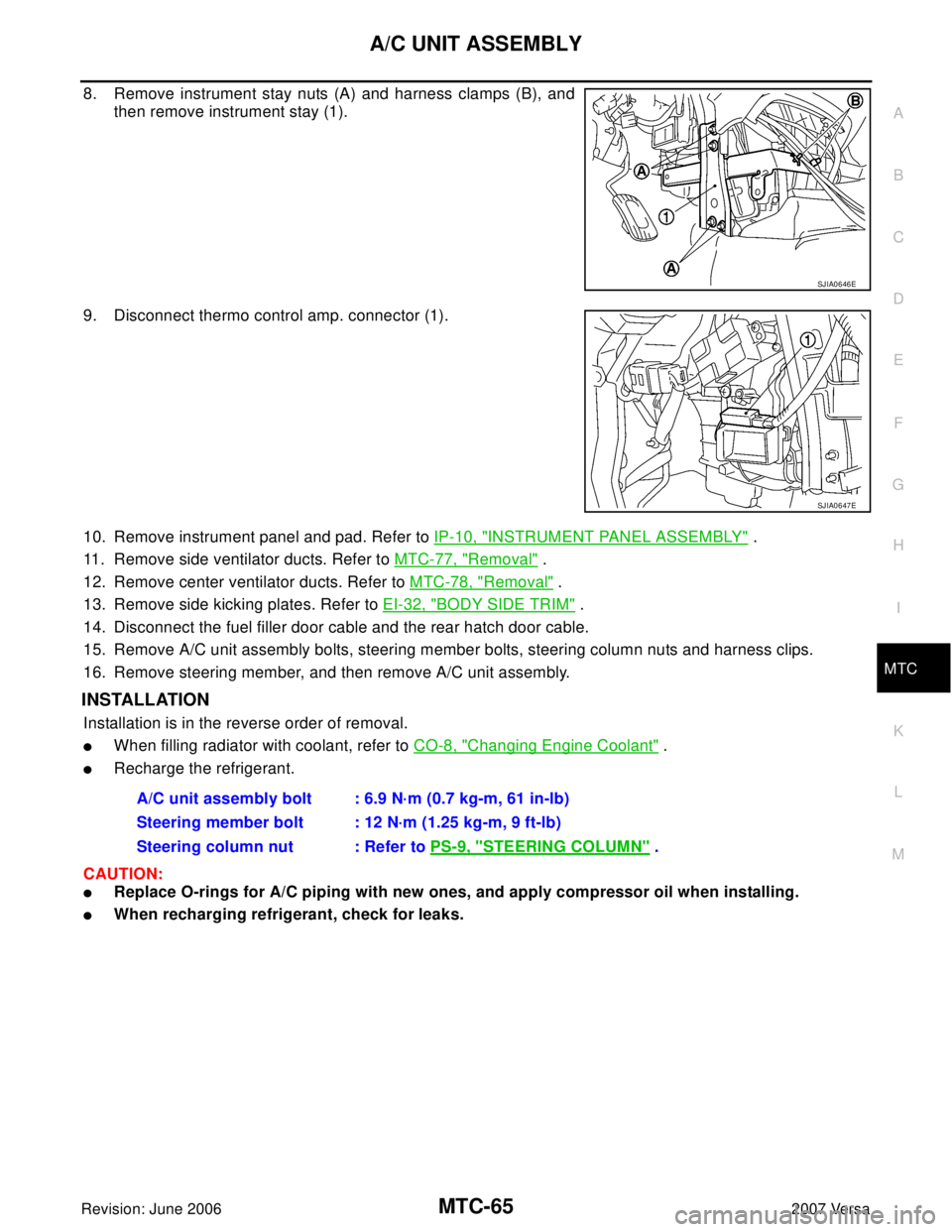
8. Remove instrument stay nuts (A) and harness clamps (B), and
then remove instrument stay (1).
9. Disconnect thermo control amp. connector (1).
10. Remove instrument panel and pad. Refer to IP-10, "
INSTRUMENT PANEL ASSEMBLY" .
11. Remove side ventilator ducts. Refer to MTC-77, "
Removal" .
12. Remove center ventilator ducts. Refer to MTC-78, "
Removal" .
13. Remove side kicking plates. Refer to EI-32, "
BODY SIDE TRIM" .
14. Disconnect the fuel filler door cable and the rear hatch door cable.
15. Remove A/C unit assembly bolts, steering member bolts, steering column nuts and harness clips.
16. Remove steering member, and then remove A/C unit assembly.
INSTALLATION
Installation is in the reverse order of removal.
�When filling radiator with coolant, refer to CO-8, "Changing Engine Coolant" .
�Recharge the refrigerant.
CAUTION:
�Replace O-rings for A/C piping with new ones, and apply compressor oil when installing.
�When recharging refrigerant, check for leaks.
SJIA0646E
SJIA0647E
A/C unit assembly bolt : 6.9 N·m (0.7 kg-m, 61 in-lb)
Steering member bolt : 12 N·m (1.25 kg-m, 9 ft-lb)
Steering column nut : Refer to PS-9, "
STEERING COLUMN" .
Page 2492 of 2896
MTC-80
REFRIGERANT LINES
Revision: June 20062007 Versa
REFRIGERANT LINESPFP:92600
HFC-134a (R-134a) Service ProcedureEJS0058D
SETTING OF SERVICE TOOLS AND EQUIPMENT
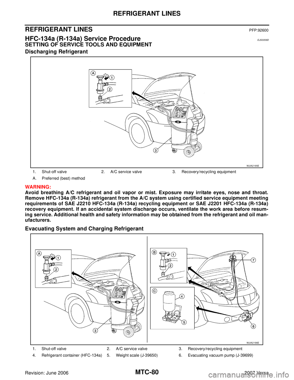
Discharging Refrigerant
WAR NIN G:
Avoid breathing A/C refrigerant and oil vapor or mist. Exposure may irritate eyes, nose and throat.
Remove HFC-134a (R-134a) refrigerant from the A/C system using certified service equipment meeting
requirements of SAE J2210 HFC-134a (R-134a) recycling equipment or SAE J2201 HFC-134a (R-134a)
recovery equipment. If an accidental system discharge occurs, ventilate the work area before resum-
ing service. Additional health and safety information may be obtained from the refrigerant and oil man-
ufacturers.
Evacuating System and Charging Refrigerant
1. Shut-off valve 2. A/C service valve 3. Recovery/recycling equipment
A. Preferred (best) method
WJIA2195E
1. Shut-off valve 2. A/C service valve 3. Recovery/recycling equipment
4. Refrigerant container (HFC-134a) 5. Weight scale (J-39650) 6. Evacuating vacuum pump (J-39699)
WJIA2196E
Page 2493 of 2896
REFRIGERANT LINES
MTC-81
C
D
E
F
G
H
I
K
L
MA
B
MTC
Revision: June 20062007 Versa
7. Manifold gauge set (J-39183) A. Preferred (best) method B. Alternative method
C. For charging
*1MTC-18, "
OIL RETURN OPERA-
TION"
*2MTC-92, "Checking for Refrigerant
Leaks"
*3MTC-94, "CHECKING PROCE-
DURE"
*4MTC-52, "PERFORMANCE TEST
DIAGNOSIS"
WJIA1923E
Page 2497 of 2896
REFRIGERANT LINES
MTC-85
C
D
E
F
G
H
I
K
L
MA
B
MTC
Revision: June 20062007 Versa
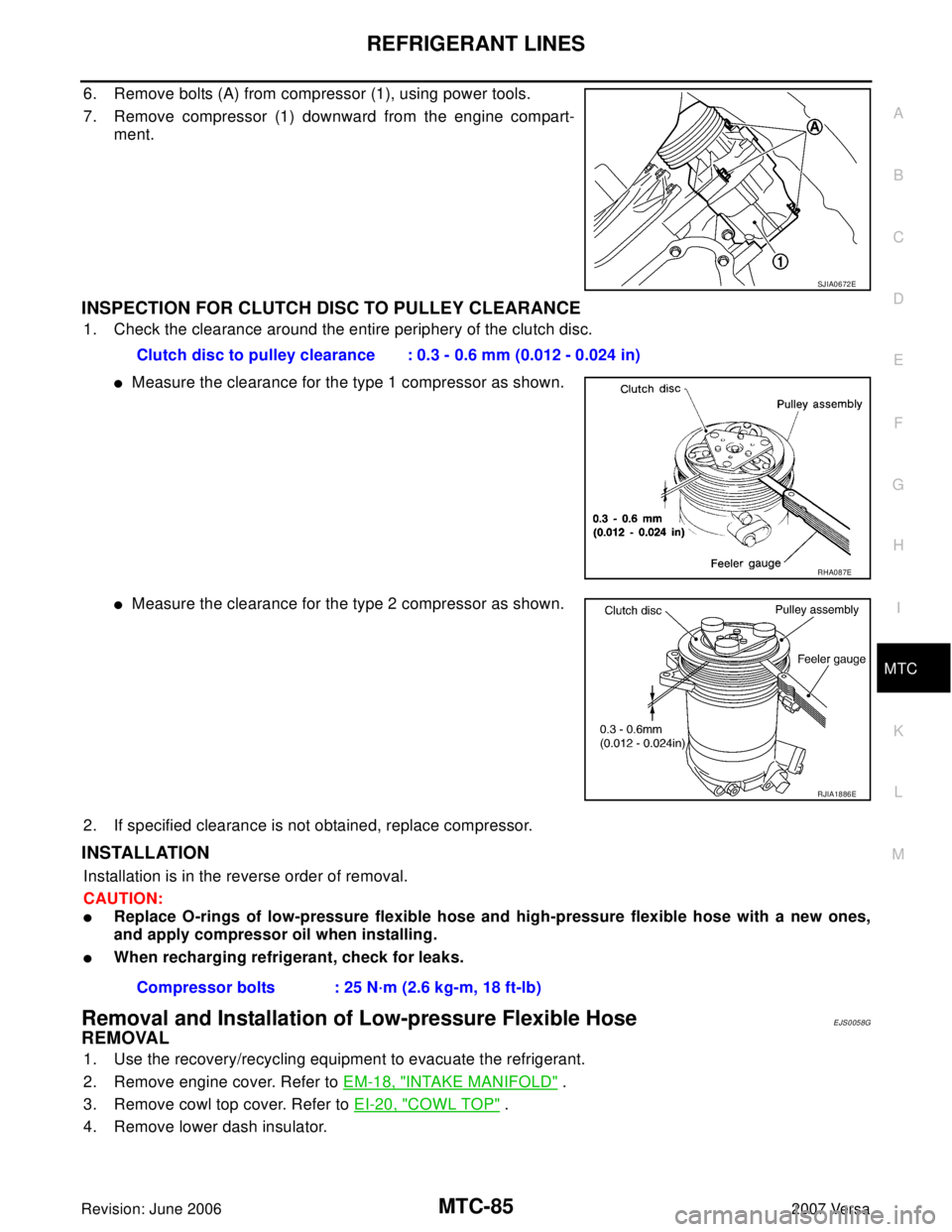
6. Remove bolts (A) from compressor (1), using power tools.
7. Remove compressor (1) downward from the engine compart-
ment.
INSPECTION FOR CLUTCH DISC TO PULLEY CLEARANCE
1. Check the clearance around the entire periphery of the clutch disc.
�Measure the clearance for the type 1 compressor as shown.
�Measure the clearance for the type 2 compressor as shown.
2. If specified clearance is not obtained, replace compressor.
INSTALLATION
Installation is in the reverse order of removal.
CAUTION:
�Replace O-rings of low-pressure flexible hose and high-pressure flexible hose with a new ones,
and apply compressor oil when installing.
�When recharging refrigerant, check for leaks.
Removal and Installation of Low-pressure Flexible HoseEJS0058G
REMOVAL
1. Use the recovery/recycling equipment to evacuate the refrigerant.
2. Remove engine cover. Refer to EM-18, "
INTAKE MANIFOLD" .
3. Remove cowl top cover. Refer to EI-20, "
COWL TOP" .
4. Remove lower dash insulator.
SJIA0672E
Clutch disc to pulley clearance : 0.3 - 0.6 mm (0.012 - 0.024 in)
RHA087E
RJIA1886E
Compressor bolts : 25 N·m (2.6 kg-m, 18 ft-lb)
Page 2498 of 2896
MTC-86
REFRIGERANT LINES
Revision: June 20062007 Versa
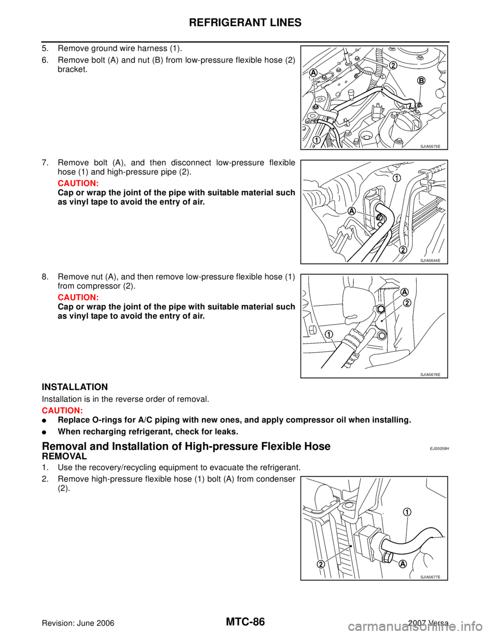
5. Remove ground wire harness (1).
6. Remove bolt (A) and nut (B) from low-pressure flexible hose (2)
bracket.
7. Remove bolt (A), and then disconnect low-pressure flexible
hose (1) and high-pressure pipe (2).
CAUTION:
Cap or wrap the joint of the pipe with suitable material such
as vinyl tape to avoid the entry of air.
8. Remove nut (A), and then remove low-pressure flexible hose (1)
from compressor (2).
CAUTION:
Cap or wrap the joint of the pipe with suitable material such
as vinyl tape to avoid the entry of air.
INSTALLATION
Installation is in the reverse order of removal.
CAUTION:
�Replace O-rings for A/C piping with new ones, and apply compressor oil when installing.
�When recharging refrigerant, check for leaks.
Removal and Installation of High-pressure Flexible HoseEJS0058H
REMOVAL
1. Use the recovery/recycling equipment to evacuate the refrigerant.
2. Remove high-pressure flexible hose (1) bolt (A) from condenser
(2).
SJIA0675E
SJIA0644E
SJIA0676E
SJIA0677E
Page 2499 of 2896
REFRIGERANT LINES
MTC-87
C
D
E
F
G
H
I
K
L
MA
B
MTC
Revision: June 20062007 Versa
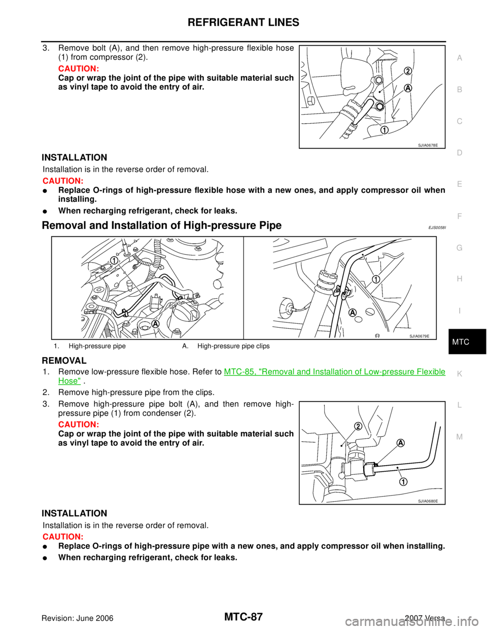
3. Remove bolt (A), and then remove high-pressure flexible hose
(1) from compressor (2).
CAUTION:
Cap or wrap the joint of the pipe with suitable material such
as vinyl tape to avoid the entry of air.
INSTALLATION
Installation is in the reverse order of removal.
CAUTION:
�Replace O-rings of high-pressure flexible hose with a new ones, and apply compressor oil when
installing.
�When recharging refrigerant, check for leaks.
Removal and Installation of High-pressure PipeEJS0058I
REMOVAL
1. Remove low-pressure flexible hose. Refer to MTC-85, "Removal and Installation of Low-pressure Flexible
Hose" .
2. Remove high-pressure pipe from the clips.
3. Remove high-pressure pipe bolt (A), and then remove high-
pressure pipe (1) from condenser (2).
CAUTION:
Cap or wrap the joint of the pipe with suitable material such
as vinyl tape to avoid the entry of air.
INSTALLATION
Installation is in the reverse order of removal.
CAUTION:
�Replace O-rings of high-pressure pipe with a new ones, and apply compressor oil when installing.
�When recharging refrigerant, check for leaks.
SJIA0678E
1. High-pressure pipe A. High-pressure pipe clips
SJIA0679E
SJIA0680E
Page 2500 of 2896
MTC-88
REFRIGERANT LINES
Revision: June 20062007 Versa
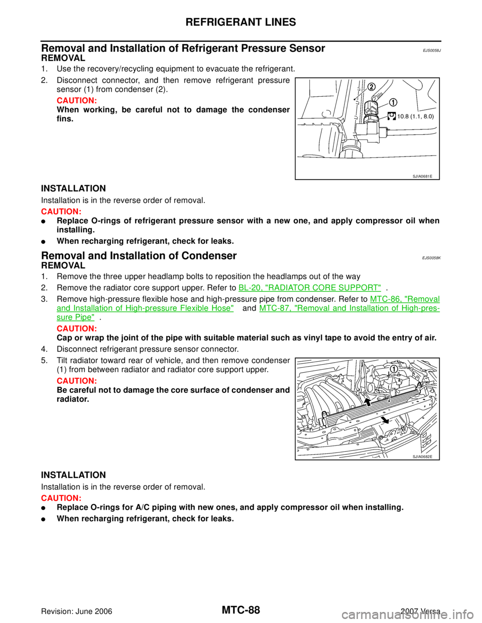
Removal and Installation of Refrigerant Pressure SensorEJS0058J
REMOVAL
1. Use the recovery/recycling equipment to evacuate the refrigerant.
2. Disconnect connector, and then remove refrigerant pressure
sensor (1) from condenser (2).
CAUTION:
When working, be careful not to damage the condenser
fins.
INSTALLATION
Installation is in the reverse order of removal.
CAUTION:
�Replace O-rings of refrigerant pressure sensor with a new one, and apply compressor oil when
installing.
�When recharging refrigerant, check for leaks.
Removal and Installation of CondenserEJS0058K
REMOVAL
1. Remove the three upper headlamp bolts to reposition the headlamps out of the way
2. Remove the radiator core support upper. Refer to BL-20, "
RADIATOR CORE SUPPORT" .
3. Remove high-pressure flexible hose and high-pressure pipe from condenser. Refer to MTC-86, "
Removal
and Installation of High-pressure Flexible Hose" and MTC-87, "Removal and Installation of High-pres-
sure Pipe" .
CAUTION:
Cap or wrap the joint of the pipe with suitable material such as vinyl tape to avoid the entry of air.
4. Disconnect refrigerant pressure sensor connector.
5. Tilt radiator toward rear of vehicle, and then remove condenser
(1) from between radiator and radiator core support upper.
CAUTION:
Be careful not to damage the core surface of condenser and
radiator.
INSTALLATION
Installation is in the reverse order of removal.
CAUTION:
�Replace O-rings for A/C piping with new ones, and apply compressor oil when installing.
�When recharging refrigerant, check for leaks.
SJIA0681E
SJIA0682E