Page 2391 of 2896
TRANSAXLE ASSEMBLY
MT-29
D
E
F
G
H
I
J
K
L
MA
B
MT
Revision: June 20062007 Versa
2. Install two way connector (1) into clutch housing.
3. Install bushings (1) until they are flush with end face of clutch
housing using a suitable tool (A).
4. Install oil channel and mainshaft front bearing outer race into
clutch housing using Tool (A).
CAUTION:
Do not reuse oil channel.
5. Install input shaft oil seal (1) into clutch housing using Tool (A).
6. Install snap ring (1) and oil channel (2) onto transaxle case.
PCIB1720E
PCIB1725E
Tool number A: KV38100200 ( — )
PCIB1724E
Tool number A: ST33220000 ( — )
PCIB1721E
PCIB1729E
Page 2392 of 2896
MT-30
TRANSAXLE ASSEMBLY
Revision: June 20062007 Versa
7. Install shim and mainshaft rear bearing outer race into transaxle
case using Tool (A).
8. Install bushings (1) into transaxle case using a suitable tool (A).
9. Install oil gutter (1) onto transaxle case.
10. Install shift lever oil seal (1) and bushing (2) into transaxle case
using a suitable tool (A).
11. Install control lever oil seal and bushings into transaxle case
using a suitable tool.
12. Install shift finger (1) into transaxle case.Tool number A: KV38100200 ( — )
PCIB1728E
PCIB1727E
PCIB1730E
PCIB1731E
PCIB1712E
Page 2393 of 2896
TRANSAXLE ASSEMBLY
MT-31
D
E
F
G
H
I
J
K
L
MA
B
MT
Revision: June 20062007 Versa
13. Install control lever (1) and then install retaining pin.
CAUTION:
Do not reuse retaining pin.
14. Install shim and differential side bearing outer race into transaxle
case using Tool (A).
15. Install differential side bearing outer race into clutch housing
using Tool (A).
16. Install differential side oil seals (1) into clutch housing and tran-
saxle case using Tool (A).
17. Install magnet onto clutch housing.
18. Install final drive assembly into clutch housing.
19. Install input shaft assembly (1), mainshaft assembly (2) and 1st-
2nd fork rod assembly (3) into clutch housing.
20. Install spring washer located under the reverse idler shaft.
PCIB1 711 E
Tool number A: ST33400001 (J-26082)
PCIB1726E
Tool number A: KV38100200 ( — )
PCIB1722E
Tool number A: KV38100300 (J-25523)
PCIB1732E
PCIB1702E
Page 2394 of 2896

MT-32
TRANSAXLE ASSEMBLY
Revision: June 20062007 Versa
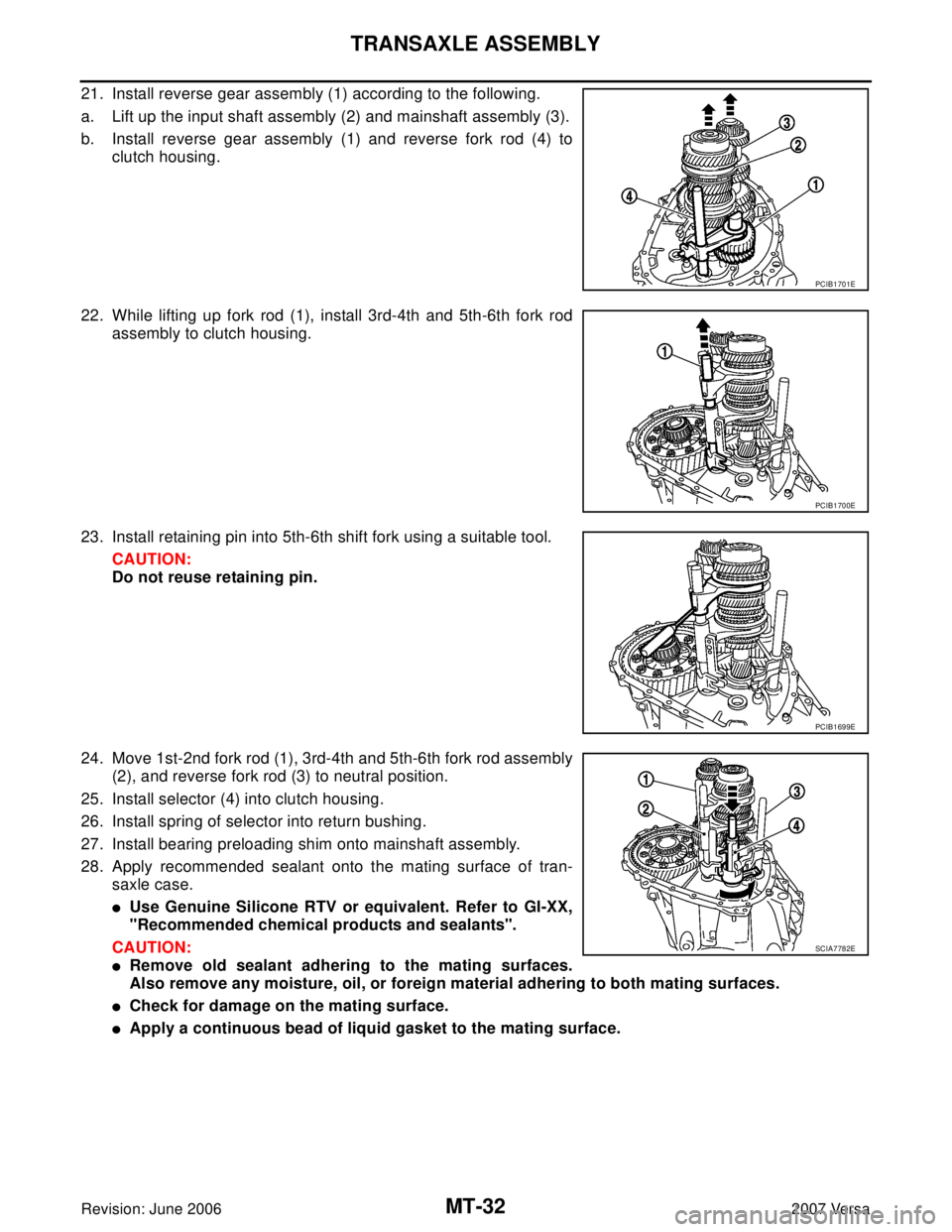
21. Install reverse gear assembly (1) according to the following.
a. Lift up the input shaft assembly (2) and mainshaft assembly (3).
b. Install reverse gear assembly (1) and reverse fork rod (4) to
clutch housing.
22. While lifting up fork rod (1), install 3rd-4th and 5th-6th fork rod
assembly to clutch housing.
23. Install retaining pin into 5th-6th shift fork using a suitable tool.
CAUTION:
Do not reuse retaining pin.
24. Move 1st-2nd fork rod (1), 3rd-4th and 5th-6th fork rod assembly
(2), and reverse fork rod (3) to neutral position.
25. Install selector (4) into clutch housing.
26. Install spring of selector into return bushing.
27. Install bearing preloading shim onto mainshaft assembly.
28. Apply recommended sealant onto the mating surface of tran-
saxle case.
�Use Genuine Silicone RTV or equivalent. Refer to GI-XX,
"Recommended chemical products and sealants".
CAUTION:
�Remove old sealant adhering to the mating surfaces.
Also remove any moisture, oil, or foreign material adhering to both mating surfaces.
�Check for damage on the mating surface.
�Apply a continuous bead of liquid gasket to the mating surface.
PCIB1701E
PCIB1700E
PCIB1699E
SCIA7782E
Page 2395 of 2896

TRANSAXLE ASSEMBLY
MT-33
D
E
F
G
H
I
J
K
L
MA
B
MT
Revision: June 20062007 Versa
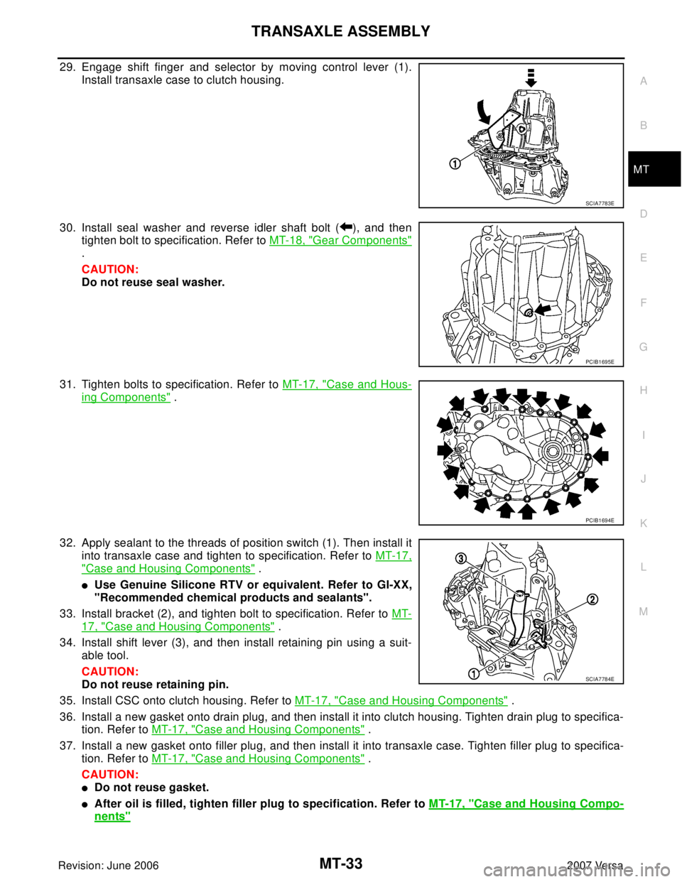
29. Engage shift finger and selector by moving control lever (1).
Install transaxle case to clutch housing.
30. Install seal washer and reverse idler shaft bolt ( ), and then
tighten bolt to specification. Refer to MT-18, "
Gear Components"
.
CAUTION:
Do not reuse seal washer.
31. Tighten bolts to specification. Refer to MT-17, "
Case and Hous-
ing Components" .
32. Apply sealant to the threads of position switch (1). Then install it
into transaxle case and tighten to specification. Refer to MT-17,
"Case and Housing Components" .
�Use Genuine Silicone RTV or equivalent. Refer to GI-XX,
"Recommended chemical products and sealants".
33. Install bracket (2), and tighten bolt to specification. Refer to MT-
17, "Case and Housing Components" .
34. Install shift lever (3), and then install retaining pin using a suit-
able tool.
CAUTION:
Do not reuse retaining pin.
35. Install CSC onto clutch housing. Refer to MT-17, "
Case and Housing Components" .
36. Install a new gasket onto drain plug, and then install it into clutch housing. Tighten drain plug to specifica-
tion. Refer to MT-17, "
Case and Housing Components" .
37. Install a new gasket onto filler plug, and then install it into transaxle case. Tighten filler plug to specifica-
tion. Refer to MT-17, "
Case and Housing Components" .
CAUTION:
�Do not reuse gasket.
�After oil is filled, tighten filler plug to specification. Refer to MT-17, "Case and Housing Compo-
nents"
SCIA7783E
PCIB1695E
PCIB1694E
SCIA7784E
Page 2411 of 2896
SERVICE DATA AND SPECIFICATIONS (SDS)
MT-49
D
E
F
G
H
I
J
K
L
MA
B
MT
Revision: June 20062007 Versa
SERVICE DATA AND SPECIFICATIONS (SDS)PFP:00030
General SpecificationsUCS006KD
Engine typeMR18DE
Transaxle modelRS6F94R
Number of speeds6
Synchromesh typeWarner
Shift pattern
Gear ratio 1st3.727
2nd2.105
3rd1.452
4th1.171
5th0.971
6th0.811
Reverse 3.687
Final gear 3.933
Number of teeth Input gear 1st 11
2nd 19
3rd 31
4th 35
5th 35
6th 37
Reverse 11
Main gear 1st 41
2nd 40
3rd 45
4th 41
5th 34
6th 30
Reverse 42
Reverse idler gear Input/Output 28/29
Final gear Final gear/Pinion 59/15
Side gear/Pinion
mate gear21/18
Oil capacity
(US pt, Imp pt)Approx. 2.0 (4-1/4, 3-1/2)
Remarks Reverse synchronizer Installed
Triple-cone synchronizer 1st and 2nd
PCIB1769E
Page 2413 of 2896

MTC-1
MANUAL AIR CONDITIONER
J AIR CONDITIONER
CONTENTS
C
D
E
F
G
H
I
K
L
M
SECTION MTC
A
B
MTC
Revision: June 20062007 Versa PRECAUTIONS .......................................................... 4
Precautions for Supplemental Restraint System
(SRS) “AIR BAG” and “SEAT BELT PRE-TEN-
SIONER” .................................................................. 4
Precautions for Procedures without Cowl Top Cover ..... 4
Precautions for Working with HFC-134a (R-134a) ..... 4
General Refrigerant Precautions .............................. 5
Oil Precautions ......................................................... 5
Precautions for Refrigerant Connection ................... 5
FEATURES OF NEW TYPE REFRIGERANT
CONNECTION ...................................................... 5
O-RING AND REFRIGERANT CONNECTION ..... 6
Precautions for Servicing Compressor ..................... 8
Precautions for Service Equipment .......................... 9
RECOVERY/RECYCLING EQUIPMENT .............. 9
ELECTRONIC LEAK DETECTOR ........................ 9
VACUUM PUMP ................................................... 9
MANIFOLD GAUGE SET ...................................... 9
SERVICE HOSES ................................................. 9
SERVICE COUPLERS ........................................ 10
REFRIGERANT WEIGHT SCALE ...................... 10
CHARGING CYLINDER ...................................... 10
Precautions for Leak Detection Dye ....................... 10
IDENTIFICATION LABEL FOR VEHICLE ........... 10
PREPARATION ......................................................... 12
Special Service Tools ............................................. 12
HFC-134a (R-134a) Service Tools and Equipment ... 12
Commercial Service Tools ...................................... 15
REFRIGERATION SYSTEM ..................................... 16
Refrigerant Cycle ................................................... 16
REFRIGERANT FLOW ....................................... 16
FREEZE PROTECTION ..................................... 16
Refrigerant System Protection ............................... 16
REFRIGERANT PRESSURE SENSOR ............. 16
PRESSURE RELIEF VALVE ............................... 16
Component Layout ................................................. 17OIL ............................................................................. 18
Maintenance of Oil Quantity in Compressor ........... 18
OIL ....................................................................... 18
OIL RETURN OPERATION ................................. 18
OIL ADJUSTING PROCEDURE FOR COMPO-
NENTS REPLACEMENT EXCEPT COMPRES-
SOR ..................................................................... 19
OIL ADJUSTING PROCEDURE FOR COM-
PRESSOR REPLACEMENT ............................... 19
AIR CONDITIONER CONTROL ............................... 21
Control Operation ................................................... 21
BLOWER CONTROL DIAL ................................. 21
TEMPERATURE CONTROL DIAL ...................... 21
MODE DOOR CONTROL DIAL .......................... 21
INTAKE DOOR LEVER ....................................... 21
REAR WINDOW DEFOGGER SWITCH ............. 21
A/C SWITCH (IF EQUIPPED) ............................. 21
Discharge Air Flow ................................................. 22
System Description ................................................. 23
SWITCHES AND THEIR CONTROL FUNCTION ... 23
CAN Communication System Description .............. 23
TROUBLE DIAGNOSIS ............................................ 24
CONSULT-II Function (BCM) ................................. 24
CONSULT-II START PROCEDURE .................... 24
DATA MONITOR ................................................. 24
How to Perform Trouble Diagnosis for Quick and
Accurate Repair ...................................................... 24
WORK FLOW ...................................................... 24
SYMPTOM TABLE .............................................. 24
Component Parts and Harness Connector Location ... 25
ENGINE COMPARTMENT .................................. 25
PASSENGER COMPARTMENT ......................... 26
Schematic ............................................................... 27
Wiring Diagram — Heater — .................................. 28
WITHOUT A/C ..................................................... 28
Wiring Diagram — A/C,M — ................................... 29
Operational Check .................................................. 33
CHECKING BLOWER ......................................... 33
CHECKING DISCHARGE AIR ............................ 33
CHECKING RECIRCULATION ........................... 33
Page 2415 of 2896
MTC-3
C
D
E
F
G
H
I
K
L
MA
B
MTC
Revision: June 20062007 Versa Dye Injection .......................................................... 92
Electronic Refrigerant Leak Detector ..................... 93
PRECAUTIONS FOR HANDLING LEAK
DETECTOR ........................................................ 93
CHECKING PROCEDURE ................................. 94
SERVICE DATA AND SPECIFICATIONS (SDS) ...... 96Compressor ............................................................ 96
Oil ........................................................................... 96
Refrigerant .............................................................. 96
Engine Idling Speed ............................................... 96
Belt Tension ............................................................ 96