Page 2425 of 2896
PREPARATION
MTC-13
C
D
E
F
G
H
I
K
L
MA
B
MTC
Revision: June 20062007 Versa
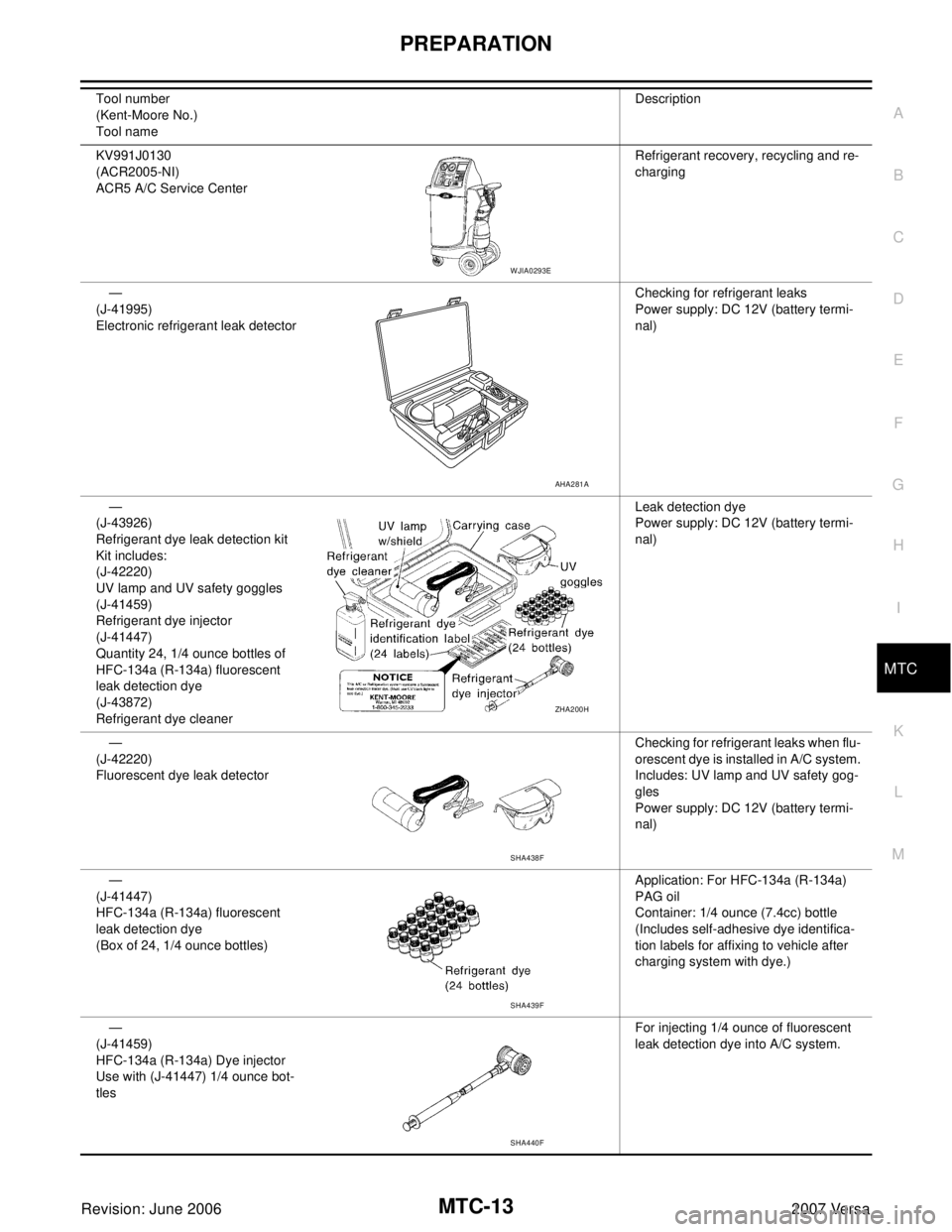
KV991J0130
(ACR2005-NI)
ACR5 A/C Service CenterRefrigerant recovery, recycling and re-
charging
—
(J-41995)
Electronic refrigerant leak detectorChecking for refrigerant leaks
Power supply: DC 12V (battery termi-
nal)
—
(J-43926)
Refrigerant dye leak detection kit
Kit includes:
(J-42220)
UV lamp and UV safety goggles
(J-41459)
Refrigerant dye injector
(J-41447)
Quantity 24, 1/4 ounce bottles of
HFC-134a (R-134a) fluorescent
leak detection dye
(J-43872)
Refrigerant dye cleanerLeak detection dye
Power supply: DC 12V (battery termi-
nal)
—
(J-42220)
Fluorescent dye leak detectorChecking for refrigerant leaks when flu-
orescent dye is installed in A/C system.
Includes: UV lamp and UV safety gog-
gles
Power supply: DC 12V (battery termi-
nal)
—
(J-41447)
HFC-134a (R-134a) fluorescent
leak detection dye
(Box of 24, 1/4 ounce bottles)Application: For HFC-134a (R-134a)
PAG oil
Container: 1/4 ounce (7.4cc) bottle
(Includes self-adhesive dye identifica-
tion labels for affixing to vehicle after
charging system with dye.)
—
(J-41459)
HFC-134a (R-134a) Dye injector
Use with (J-41447) 1/4 ounce bot-
tlesFor injecting 1/4 ounce of fluorescent
leak detection dye into A/C system. Tool number
(Kent-Moore No.)
Tool nameDescription
WJIA0293E
AHA2 81 A
ZHA2 00 H
SHA438F
SHA439F
SHA440F
Page 2426 of 2896
MTC-14
PREPARATION
Revision: June 20062007 Versa
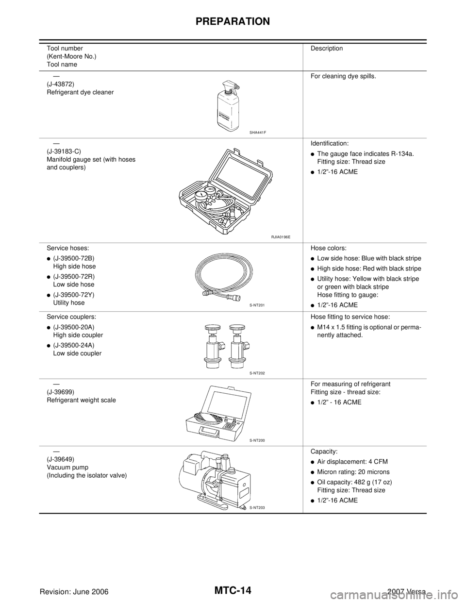
—
(J-43872)
Refrigerant dye cleanerFor cleaning dye spills.
—
(J-39183-C)
Manifold gauge set (with hoses
and couplers)Identification:
�The gauge face indicates R-134a.
Fitting size: Thread size
�1/2”-16 ACME
Service hoses:
�(J-39500-72B)
High side hose
�(J-39500-72R)
Low side hose
�(J-39500-72Y)
Utility hoseHose colors:
�Low side hose: Blue with black stripe
�High side hose: Red with black stripe
�Utility hose: Yellow with black stripe
or green with black stripe
Hose fitting to gauge:
�1/2”-16 ACME
Service couplers:
�(J-39500-20A)
High side coupler
�(J-39500-24A)
Low side couplerHose fitting to service hose:
�M14 x 1.5 fitting is optional or perma-
nently attached.
—
(J-39699)
Refrigerant weight scaleFor measuring of refrigerant
Fitting size - thread size:
�1/2” - 16 ACME
—
(J-39649)
Vacuum pump
(Including the isolator valve)Capacity:
�Air displacement: 4 CFM
�Micron rating: 20 microns
�Oil capacity: 482 g (17 oz)
Fitting size: Thread size
�1/2”-16 ACME Tool number
(Kent-Moore No.)
Tool nameDescription
SHA441F
RJIA0196E
S-NT201
S-NT202
S-NT200
S-NT203
Page 2427 of 2896
PREPARATION
MTC-15
C
D
E
F
G
H
I
K
L
MA
B
MTC
Revision: June 20062007 Versa
Commercial Service ToolsEJS00590
(Kent-Moore No.)
Tool nameDescription
(J-41810-NI)
Refrigerant identifier equipment (R-
134a)For checking refrigerant purity and
system contamination
Power toolLoosening bolts and nuts
(J-44614)
Clutch disc holding toolClutch disc holding tool
RJIA0197E
PBIC0190E
WHA230
Page 2446 of 2896
MTC-34
TROUBLE DIAGNOSIS
Revision: June 20062007 Versa
Mode DoorEJS0057K
SYMPTOM: Air outlet does not change.
INSPECTION FLOW
1. CONFIRM SYMPTOM BY PERFORMING OPERATIONAL CHECK - DISCHARGE AIR
1. Rotate the mode door control dial to each position.
2. Confirm that discharge air comes out according to the air distribution table. Refer to MTC-22, "
Discharge
Air Flow" .
NOTE:
Confirm that the compressor clutch (with A/C) is engaged (visual inspection) when DEF ( ) or D/F ( )
is selected.
Can a symptom be duplicated?
YES >> GO TO 3.
NO >> GO TO 2.
2. PERFORM COMPLETE OPERATIONAL CHECK
Perform a complete operational check and check for any symptoms. Refer to MTC-33, "
Operational Check" .
Can a symptom be duplicated?
YES >> Refer to MTC-24, "SYMPTOM TABLE" .
NO >> System OK.
3. CHECK FOR SERVICE BULLETINS
Check for any service bulletins.
>> GO TO 4.
4. CHECK MODE DOOR CONTROL CABLE
Check and verify mode door mechanism for smooth operation in each mode.
OK or NG
OK >> If the symptom still exists, perform a complete operational check and check for other symptoms.
Refer to MTC-33, "
Operational Check" . If other symptoms exist, refer to MTC-24, "SYMPTOM
TABLE" .
NG >> Repair or adjust mode door control cable. Refer to MTC-71, "
Mode Door Cable Adjustment" .
Page 2447 of 2896
TROUBLE DIAGNOSIS
MTC-35
C
D
E
F
G
H
I
K
L
MA
B
MTC
Revision: June 20062007 Versa
Air Mix DoorEJS0057L
SYMPTOM: Air mix door does not change.
INSPECTION FLOW
1. CONFIRM SYMPTOM BY PERFORMING OPERATIONAL CHECK - TEMPERATURE INCREASE
1. Turn the temperature control dial clockwise until maximum heat.
2. Check for hot air at discharge air outlets.
>> GO TO 2.
2. CONFIRM SYMPTOM BY PERFORMING OPERATIONAL CHECK - TEMPERATURE DECREASE
1. Turn the temperature control dial counterclockwise until maximum cold.
2. Check for cold air at discharge air outlets.
Can a symptom be duplicated?
YES >> GO TO 4.
NO >> GO TO 3.
3. PERFORM COMPLETE OPERATIONAL CHECK
Perform a complete operational check and check for any symptoms. Refer to MTC-33, "
Operational Check" .
Can a symptom be duplicated?
YES >> Refer to MTC-24, "SYMPTOM TABLE" .
NO >> System OK.
4. CHECK FOR SERVICE BULLETINS
Check for any service bulletins.
>> GO TO 5.
5. CHECK AIR MIX DOOR CONTROL LINKAGE
Check and verify air mix door mechanism for smooth operation.
OK or NG
OK >> If the symptom still exists, perform a complete operational check. Refer to MTC-33, "Operational
Check" . If other symptoms exist, refer to MTC-24, "SYMPTOM TABLE" .
NG >> Repair or adjust air mix door control linkage. Refer to MTC-70, "
Air Mix Door Cable Adjustment" .
Page 2448 of 2896
MTC-36
TROUBLE DIAGNOSIS
Revision: June 20062007 Versa
Intake Door EJS0057M
SYMPTOM:
�Intake door does not change.
INSPECTION FLOW
1. CONFIRM SYMPTOM BY PERFORMING OPERATIONAL CHECK - REC ( )
1. Slide the intake door lever to the REC ( ) position.
2. Turn the blower motor to maximum speed.
3. Slide the intake door lever to the FRE position.
4. Listen for intake door position change (you should hear blower sound change slightly).
Can a symptom be duplicated?
YES >> GO TO 3.
NO >> GO TO 2.
2. PERFORM COMPLETE OPERATIONAL CHECK
Perform a complete operational check and check for any symptoms. Refer to MTC-33, "
Operational Check" .
Can a symptom be duplicated?
YES >> Refer to MTC-24, "SYMPTOM TABLE" .
NO >> System OK.
3. CHECK FOR SERVICE BULLETINS
Check for any service bulletins.
>> GO TO 4.
4. CHECK INTAKE DOOR CONTROL LINKAGE
Check intake door control linkage mechanism for smooth operation.
OK or NG
OK >> If the symptom still exists, perform a complete operational check. Refer to MTC-33, "Operational
Check" . If other symptoms exist, refer to MTC-24, "SYMPTOM TABLE" .
NG >> Repair or adjust control linkage. Refer to MTC-69, "
Intake Door Cable Adjustment" .
Page 2449 of 2896
TROUBLE DIAGNOSIS
MTC-37
C
D
E
F
G
H
I
K
L
MA
B
MTC
Revision: June 20062007 Versa
Blower Motor CircuitEJS0057N
SYMPTOM: Front blower motor operation is malfunctioning.
INSPECTION FLOW
1. CONFIRM SYMPTOM BY PERFORMING OPERATIONAL CHECK - FRONT BLOWER
1. Turn blower control dial to "1" position. Blower should operate on low speed.
2. Turn the blower control dial to "2" position, and continue checking blower speed until all speeds are
checked.
Can the symptom be duplicated?
YES >> GO TO 3.
NO >> GO TO 2.
2. PERFORM COMPLETE OPERATIONAL CHECK
Perform a complete operational check and check for any symptoms. Refer to MTC-33, "
Operational Check" .
Can a symptom be duplicated?
YES >> Refer to MTC-24, "SYMPTOM TABLE" .
NO >> System OK.
3. CHECK FOR SERVICE BULLETINS
Check for any service bulletins.
>> GO TO 4.
4. CHECK FRONT BLOWER MOTOR CIRCUIT
Check front blower motor circuit. Refer to MTC-38, "
DIAGNOSTIC PROCEDURE FOR BLOWER MOTOR" .
OK or NG?
OK >> If the symptom still exists, perform a complete operational check. Refer to MTC-33, "Operational
Check" . If other symptoms exist, refer to MTC-24, "SYMPTOM TABLE" .
NG >> Repair as necessary.
Page 2453 of 2896
TROUBLE DIAGNOSIS
MTC-41
C
D
E
F
G
H
I
K
L
MA
B
MTC
Revision: June 20062007 Versa
Magnet Clutch Circuit (If Equipped)EJS0057O
SYMPTOM: Magnet clutch does not engage.
INSPECTION FLOW
1. CONFIRM SYMPTOM BY PERFORMING OPERATIONAL CHECK - MAGNET CLUTCH
1. Turn ignition switch ON.
2. Turn blower control dial to the desired (1 to 4 speed) position.
3. Press the A/C switch. A/C indicator will turn on.
4. Confirm that the compressor clutch engages (sound or visual inspection).
Can the symptom be duplicated?
YES >> GO TO 3.
NO >> GO TO 2.
2. CHECK FOR ANY SYMPTOMS
Perform a complete operational check for any symptoms. Refer to MTC-33, "
Operational Check" .
Does another symptom exist?
YES >> Refer to MTC-24, "SYMPTOM TABLE" .
NO >> System OK.
3. CHECK FOR SERVICE BULLETINS
Check for any service bulletins.
>> GO TO 4.
4. CHECK COMPRESSOR BELT TENSION
Check compressor belt tension. Refer to EM-13, "
Checking Drive Belts" .
OK or NG
OK >> GO TO 5.
NG >> Adjust or replace A/C compressor belt.
5. CHECK REFRIGERANT PRESSURE
Check refrigerant pressure with manifold gauge connected. Refer to MTC-54, "
Test Reading" .
OK or NG
OK >> GO TO 6.
NG >> Perform trouble diagnosis for unusual pressure. Refer to MTC-55, "
TROUBLE DIAGNOSIS FOR
UNUSUAL PRESSURE" .
6. CHECK MAGNET CLUTCH CIRCUIT
Perform diagnostic procedure for the magnetic clutch. Refer to MTC-42, "
DIAGNOSTIC PROCEDURE FOR
MAGNET CLUTCH" .
OK or NG
OK >> If the symptom still exists, perform a complete operational check. Refer to MTC-33, "Operational
Check" . If other symptoms exist, refer to MTC-24, "SYMPTOM TABLE" .
NG >> Repair as necessary.