TROUBLE DIAGNOSIS
STC-13
[EPS]
C
D
E
F
H
I
J
K
L
MA
B
STC
Revision: June 20062007 Versa
CONSULT-II Function (EPS)UGS0007Y
FUNCTION
CONSULT-II can display each diagnostic item using the diagnostic test modes shown following.
CONSULT-II SETTING PROCEDURE
Refer to GI-38, "CONSULT-II Start Procedure" .
SELF-DIAG RESULTS MODE
Operation Procedure
1. Perform “CONSULT-II Start Procedure”. Refer to GI-38, "CONSULT-II Start Procedure" .
2. With engine at idle, touch “SELF-DIAG RESULTS”. Display
shows malfunction experienced since the last erasing operation.
NOTE:
�When malfunction occurred at the same time, it is dis-
played to a 3 system at the maximum.
�The details for “TIME” are as follow:
–“0”: Error currently detected with EPS control unit.
–Except for “0”: Error detected in the past and memorized
with EPS control unit.
Detects frequency of driving after DTC occurs (frequency
of turning ignition switch “ON”).
Display Item List
CAUTION:
If “CAN COMM CIRCUIT [U1000]” is displayed with other DTCs, first perform the trouble diagnosis for CAN communication
line.
How to Erase Self-Diagnostic Results
1. Perform applicable inspection of malfunctioning item and then repair or replace.
Diagnostic test mode Function Reference page
Self-diagnostic results
�Self-diagnostic results can be read and erased quickly.STC-13
Data monitor�Input/Output data in the EPS control unit can be read.STC-14
CAN diagnostic support monitor�The results of transmit/receive diagnosis of CAN communication can be read.LAN-44
ECU part number�EPS control unit part number can be read.STC-14
SGIA1531E
Item
(CONSULT-II screen terms)Diagnostic item is detected when.... Check item
BATTERY VOLT
[C1601]When the power supply malfunction supplied to EPS control unit is
detected.STC-16, "
DTC C1601
BATTERY VOLT"
TORQUE SENSOR
[C1604]When the torque sensor malfunction assembled in steering column
assembly is detected. STC-19, "DTC C1604
TORQUE SENSOR"
EPS MOTOR
[C1606]When the motor driver malfunction of EPS control unit or EPS motor
malfunction is detected.STC-21, "DTC C1606
EPS MOTOR"
EEPROM
[C1607]When the memory (EEPROM) system malfunction is detected in
EPS control unit.STC-22, "DTC C1607
EEPROM"
CONTROL UNIT
[C1608]When the internal malfunction is detected in EPS control unit.STC-22, "DTC C1608
CONTROL UNIT"
CAN VHCL SPEED
[C1609]When the malfunction is detected in vehicle speed signal received
with CAN communication.STC-23, "DTC C1609
CAN VHCL SPEED"
CAN ENG RPM
[C1610]When the malfunction is detected in engine status signal received
with CAN communication.STC-24, "DTC C1610
CAN ENG RPM"
CAN COMM CIRCUIT
[U1000]When EPS control unit is not transmitting or receiving CAN commu-
nication signal 2 seconds or more.STC-24, "DTC U1000
CAN COMM CIRCUIT"
NO DTC IS DETECTED.
FURTHER TESTING MAY BE
REQUIRED.No NG item has been detected. —
WT-14
TROUBLE DIAGNOSES
Revision: June 20062007 Versa
CONSULT-II Function (BCM)EES002F0
CONSULT-II can display each diagnostic item using the diagnostic test modes shown following.
BCM
diagnostic test itemDiagnostic mode Description
Inspection by partWORK SUPPORTSupports inspections and adjustments. Commands are transmit-
ted to the BCM for setting the status suitable for required opera-
tion, input/output signals are received from the BCM and received
data is displayed.
DATA MONITOR Displays BCM input/output data in real time.
ACTIVE TESTOperation of electrical loads can be checked by sending drive sig-
nal to them.
SELF-DIAG RESULTS Displays BCM self-diagnosis results.
CAN DIAG SUPPORT MNTRThe result of transmit/receive diagnosis of CAN communication
can be read.
ECU PART NUMBER BCM part number can be read.
CONFIGURATION Performs BCM configuration read/write functions.
TROUBLE DIAGNOSES
WT-15
C
D
F
G
H
I
J
K
L
MA
B
WT
Revision: June 20062007 Versa
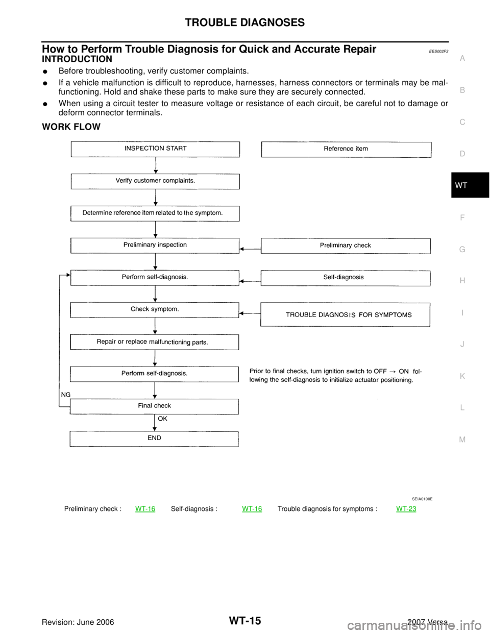
How to Perform Trouble Diagnosis for Quick and Accurate RepairEES002F3
INTRODUCTION
�Before troubleshooting, verify customer complaints.
�If a vehicle malfunction is difficult to reproduce, harnesses, harness connectors or terminals may be mal-
functioning. Hold and shake these parts to make sure they are securely connected.
�When using a circuit tester to measure voltage or resistance of each circuit, be careful not to damage or
deform connector terminals.
WORK FLOW
Preliminary check :WT-16Self-diagnosis :WT-16Trouble diagnosis for symptoms :WT-23
SEIA0100E
![NISSAN VERSA 2006 Workshop Service Repair Manual TROUBLE DIAGNOSIS
STC-13
[EPS]
C
D
E
F
H
I
J
K
L
MA
B
STC
Revision: June 20062007 Versa
CONSULT-II Function (EPS)UGS0007Y
FUNCTION
CONSULT-II can display each diagnostic item using the diagnostic test](/manual-img/5/57401/w960_57401-2798.png "NISSAN VERSA 2006 Workshop Service Repair Manual TROUBLE DIAGNOSIS
STC-13
[EPS]
C
D
E
F
H
I
J
K
L
MA
B
STC
Revision: June 20062007 Versa
CONSULT-II Function (EPS)UGS0007Y
FUNCTION
CONSULT-II can display each diagnostic item using the diagnostic test")
EES002F0
CONSULT-II can display each diagnostic item using the diagnostic test modes shown following.
BCM
diagnostic test")