Page 2355 of 2896

CHASSIS AND BODY MAINTENANCE
MA-21
C
D
E
F
G
H
I
J
K
MA
B
MA
Revision: June 20062007 Versa
6. Wipe fluid off the CVT fluid level gauge. Then rotate the CVT
fluid level gauge 180° and re-insert it into the CVT charging pipe
as far as it will go.
CAUTION:
Always use lint free paper towels to wipe fluid off the CVT
fluid level gauge.
7. Remove the CVT fluid level gauge and check that the fluid level
is within the specified range as shown. If the fluid level is at or
below the low side of the range, add the necessary specified
NISSAN CVT fluid through the CVT charging pipe.
CAUTION:
�Only use specified NISSAN CVT fluid.
�Do not overfill the CVT.
8. Install the CVT fluid level gauge to the CVT fluid charging pipe until it locks.
CAUTION:
When CVT fluid level gauge is installed into the CVT fluid charging pipe, make sure that the CVT
fluid level gauge is securely locked in place.
FLUID CONDITION CHECK
Changing CVT FluidELS0021W
1. Warm up CVT fluid by driving the vehicle for 10 minutes.
�: Vehicle front
�Radiator (2)
�CVT fluid cooler hose [inlet side (3)]
�Transaxle assembly (4)
2. Drain CVT fluid from CVT fluid cooler hose [outlet side (1)] and
refill with new specified NISSAN CVT fluid in the CVT fluid
charging pipe with the engine running at idle speed.
CAUTION:
Only use the specified NISSAN CVT fluid.
3. Refill until new CVT fluid comes out from CVT fluid cooler hose [outlet side (1)].
SCIA1931E
Fluid grade: Refer to MA-11, "Fluids and Lubri-
cants" .
SCIA1932E
Fluid status Conceivable cause Required operation
Varnished (viscous
varnish state)Clutch, brake
scorchedReplace the CVT fluid and check the
CVT main unit and the vehicle for
malfunctions (wire harness, cooler
pipes, etc.)
Milky white or
cloudyWater in the fluid Replace the CVT fluid and check for
places where water is getting in.
Large amount of
metal powder mixed
in fluidUnusual wear of
sliding parts within
CVTReplace the CVT fluid and check for
improper operation of the CVT.
ATA0022D
Fluid capacity and grade: Refer to MA-11, "Fluids
and Lubricants" .SCIA6088E
Page 2375 of 2896
 of select cable (2) and then remove it
from select lever (3).
5. Shift control lever to neu")
CONTROL LINKAGE
MT-13
D
E
F
G
H
I
J
K
L
MA
B
MT
Revision: June 20062007 Versa
b. Pull the release button (1) of select cable (2) and then remove it
from select lever (3).
5. Shift control lever to neutral position.
6. Remove control lever knob.
7. Remove center console assembly. Refer to IP-22, "
CENTER
CONSOLE ASSEMBLY" .
8. Remove control device assembly bolts.
9. Remove exhaust front tube, center muffler and heat plate. Refer
to EX-4, "
Removal and Installation" .
10. Remove cable support bracket.
11. Remove select cable and shift cable from cable bracket.
12. Remove control device assembly from the vehicle.
INSTALLATION
Installation is in the reverse order of removal.
NOTE:
Self tapping bolts are used to attach cables to the clutch housing.
�Securely assemble each cable and lever of control shaft.
�Be careful about the installation direction, and push control lever
knob onto control lever.
CAUTION:
Do not reuse control lever knob.
�Make sure that the front/rear claws (1) of control device assem-
bly are in contact with flange of the floor (2).
�When control lever is selected to 1st-2nd side and 5th-6th side,
confirm control lever returns to neutral position smoothly.
�When control lever is shifted to each position, make sure there
is no binding or disconnection in each boot.
�Move stopper (1) to lock position when installing the shift cable
onto the shift lever.
WCIA0606E
SCIA7630E
PCIB1510E
SCIA7846E
Page 2376 of 2896

MT-14
AIR BREATHER HOSE
Revision: June 20062007 Versa
AIR BREATHER HOSEPFP:31098
Removal and InstallationUCS005LO
COMPONENTS
REMOVAL
1. Remove battery. Refer to SC-9, "Removal and Installation"
2. Remove air duct (Inlet), air duct and air cleaner case. Refer to EM-16, "Removal and Installation" .
3. Remove air breather hose.
CAUTION:
When air breather hose is removed, be sure to hold two way connector securely.
INSTALLATION
Installation is in the reverse order of removal.
�When installing air breather hose on two way connector, aim paint mark face toward the vehicle front.
�When installing air breather hose on two way connector, push it until it hits transaxle case.
�When installing air breather hose to air duct and air cleaner case, make sure that clips are fully inserted.
CAUTION:
Make sure air breather hose is not collapsed or blocked due to folding or bending when installed.
1. Air cleaner case 2. Air breather hose 3. Air duct
4. Clip 5. Transaxle assembly 6. 2 way connector
SCIA7629E
Page 2399 of 2896
INPUT SHAFT AND GEARS
MT-37
D
E
F
G
H
I
J
K
L
MA
B
MT
Revision: June 20062007 Versa
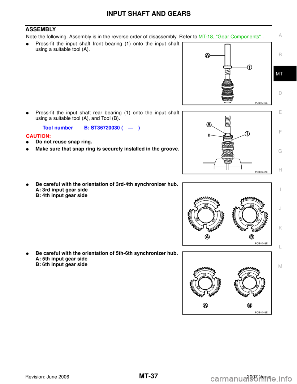
ASSEMBLY
Note the following. Assembly is in the reverse order of disassembly. Refer to MT-18, "Gear Components" .
�Press-fit the input shaft front bearing (1) onto the input shaft
using a suitable tool (A).
�Press-fit the input shaft rear bearing (1) onto the input shaft
using a suitable tool (A), and Tool (B).
CAUTION:
�Do not reuse snap ring.
�Make sure that snap ring is securely installed in the groove.
�Be careful with the orientation of 3rd-4th synchronizer hub.
A: 3rd input gear side
B: 4th input gear side
�Be careful with the orientation of 5th-6th synchronizer hub.
A: 5th input gear side
B: 6th input gear side
PCIB1746E
Tool number B: ST36720030 ( — )
PCIB1747E
PCIB1748E
PCIB1749E
Page 2406 of 2896
MT-44
REVERSE IDLER SHAFT AND GEARS
Revision: June 20062007 Versa
5. Remove needle bearings (1) from reverse idler shaft.
ASSEMBLY
Assembly is in the reverse order of disassembly. Refer to MT-18, "Gear Components"
CAUTION:
�Do not reuse snap ring.
�Make sure that snap ring is securely installed in the groove.
PCIB1761E
Page 2408 of 2896

MT-46
FINAL DRIVE
Revision: June 20062007 Versa
INSPECTION AFTER DISASSEMBLY
Gear, Washer, Shaft and Case
�Check side gears, thrust washer, pinion mate shaft, pinion mate
gears, lock ring and differential case. If necessary, replace with
a new one.
Bearing
�Check for bearing damage and rough rotation. If necessary,
replace with a new one.
CAUTION:
When replacing tapered roller bearing, replace outer and inner
races as a set.
ASSEMBLY
1. Install pinion mate shaft, pinion mate gears, side gears and thrust washer into differential case.
2. Install lock ring (1) onto differential case.
CAUTION:
Make sure that lock ring is securely installed in the groove.
3. Install final gear into differential case, and tighten final gear
bolts to specification. Refer to MT-22, "
Final Drive Components"
.
4. Install speedometer drive gear onto differential case.
5. Press-fit the differential side bearing inner race (clutch housing
side) onto the differential case using a suitable tool (A).
PCIB0977J
SPD7 15
PCIB1764E
PCIB1762E
Page 2436 of 2896
EJS0057E
CONSULT-II can display each diagnostic item using the diagnostic test modes shown fo")
MTC-24
TROUBLE DIAGNOSIS
Revision: June 20062007 Versa
TROUBLE DIAGNOSISPFP:00004
CONSULT-II Function (BCM)EJS0057E
CONSULT-II can display each diagnostic item using the diagnostic test modes shown following.
CONSULT-II START PROCEDURE
Refer to GI-38, "CONSULT-II Start Procedure" .
DATA MONITOR
Display Item List
How to Perform Trouble Diagnosis for Quick and Accurate RepairEJS0057F
WORK FLOW
SYMPTOM TABLE
BCM diagnostic
test itemDiagnostic mode Description
Inspection by partWORK SUPPORTSupports inspections and adjustments. Commands are transmitted to the BCM
for setting the status suitable for required operation, input/output signals are
received from the BCM and received data is displayed.
DATA MONITOR Displays BCM input/output data in real time.
ACTIVE TEST Operation of electrical loads can be checked by sending drive signal to them.
SELF-DIAG RESULTS Displays BCM self-diagnosis results.
CAN DIAG SUPPORT MNTR The result of transmit/receive diagnosis of CAN communication can be read.
ECU PART NUMBER BCM part number can be read.
CONFIGURATION Performs BCM configuration read/write functions.
Monitor item name
“operation or unit”Contents
IGN ON SW “ON/OFF”Displays “IGN Position (ON)/OFF, ACC Position (OFF)” status as judged from ignition switch signal
through the CAN communication.
FAN ON SIG “ON/OFF”Displays “FAN (ON)/FAN (OFF)” status as judged from blower fan motor switch signal through CAN
communication.
AIR COND SW “ON/OFF”Displays “COMP (ON)/COMP (OFF)” status as judged from air conditioner switch signal through the
CAN communication.
*1MTC-33, "Operational Check"
SHA9 00 E
Symptom Reference Page
Air outlet does not change. Go to Trouble Diagnosis Procedure for Mode Door.MTC-34
Discharge air temperature does not
change.Go to Trouble Diagnosis Procedure for Air Mix Door.MTC-35
Intake door does not change. Go to Trouble Diagnosis Procedure for Intake Door.MTC-36
Blower motor operation is malfunctioning. Go to Trouble Diagnosis Procedure for Blower Motor.MTC-37
Magnet clutch does not engage in A/C,
defrost/foot, or defrost mode.Go to Trouble Diagnosis Procedure for Magnet Clutch.MTC-41
Page 2474 of 2896
MTC-62
CONTROLLER
Revision: June 20062007 Versa
Disassembly and AssemblyEJS00581
CAUTION:
Install inner cable of each door cable to the corresponding
lever, as shown in the figure. Press outer cable until it hooks on
the tabs and becomes secure.
1. Air mix door cable 2. Intake door cable 3. Mode door cable
4. A/C controller assembly 5. Mode control dial 6. Rear DEF button
7. A/C button 8. Temperature control dial 9. Illumination bulb
10. Intake door lever knob 11. Fan control dial
ZJIA0106J
MJIA0038E
 from reverse idler shaft.
ASSEMBLY
Assembly is in the reverse order of disassembly. Refer to MT-18, \"Gea")
