Page 1709 of 2896
 sensor 1 is a planar one-cell limit current sen-
sor.")
EC-540Revision: June 2006
DTC P2A00 A/F SENSOR 1
2007 Versa
DTC P2A00 A/F SENSOR 1PFP:22693
Component DescriptionUBS00QNP
The air fuel ratio (A/F) sensor 1 is a planar one-cell limit current sen-
sor. The sensor element of the A/F sensor 1 is composed an elec-
trode layer, which transports ions. It has a heater in the element.
The sensor is capable of precise measurement = 1, but also in the
lean and rich range. Together with its control electronics, the sensor
outputs a clear, continuous signal throughout a wide range.
The exhaust gas components diffuse through the diffusion layer at
the sensor cell. An electrode layer is applied voltage, and this current
relative oxygen density in lean. Also this current relative hydrocar-
bon density in rich.
Therefore, the A/F sensor 1 is able to indicate air fuel ratio by this
electrode layer of current. In addition, a heater is integrated in the
sensor to ensure the required operating temperature of about 800°C
(1,472°F).
CONSULT-II Reference Value in Data Monitor ModeUBS00QNQ
Specification data are reference values.
On Board Diagnosis LogicUBS00QNR
To judge the malfunction, the A/F signal computed by ECM from the A/F sensor 1 signal is monitored not to be
shifted to LEAN side or RICH side.
PBIB3353E
PBIB3354E
MONITOR ITEM CONDITION SPECIFICATION
A/F SEN1 (B1)
�Engine: After warming upMaintaining engine speed at
2,000 rpmFluctuates around 2.2V
DTC No. Trouble diagnosis name DTC detecting condition Possible Cause
P2A00
2A00Air fuel ratio (A/F) sensor 1
circuit range/performance
�The output voltage computed by ECM from the
A/F sensor 1 signal is shifted to the lean side
for a specified period.
�The A/F signal computed by ECM from the A/F
sensor 1 signal is shifted to the rich side for a
specified period.
�Air fuel ratio (A/F) sensor 1
�Air fuel ratio (A/F) sensor 1 heater
�Fuel pressure
�Fuel injector
�Intake air leaks
Page 1712 of 2896

DTC P2A00 A/F SENSOR 1
EC-543
C
D
E
F
G
H
I
J
K
L
MA
EC
Revision: June 20062007 Versa
Specification data are reference values and are measured between each terminal and ground.
Pulse signal is measured by CONSULT-II.
CAUTION:
Do not use ECM ground terminals when measuring input/output voltage. Doing so may result in dam-
age to the ECM's transistor. Use a ground other than ECM terminals, such as the ground.
: Average voltage for pulse signal (Actual pulse signal can be confirmed by oscilloscope.)
Diagnostic ProcedureUBS00QNU
1. CHECK GROUND CONNECTIONS
1. Turn ignition switch OFF.
2. Loosen and retighten ground screws on the body.
Refer to EC-150, "
Ground Inspection" .
OK or NG
OK >> GO TO 2.
NG >> Repair or replace ground connections.
TERMI-
NAL
NO.WIRE
COLORITEM CONDITION DATA (DC Voltage)
3 G A/F sensor 1 heater[Engine is running]
�Warm-up condition
�Idle speed
(More than 140 seconds after starting
engine)Approximately 2.9 - 8.8V
49 W A/F sensor 1[Engine is running]
�Warm-up condition
�Engine speed: 2,000 rpmApproximately 1.8V
Output voltage varies with air fuel
ratio.
53 B A/F sensor 1[Ignition switch: ON]Approximately 2.2V
PBIA8148J
:Vehicle front
1. Body ground E24 2. Engine ground F9 3. Engine ground F16
4. Body ground E15
BBIA0698E
Page 1713 of 2896
EC-544Revision: June 2006
DTC P2A00 A/F SENSOR 1
2007 Versa
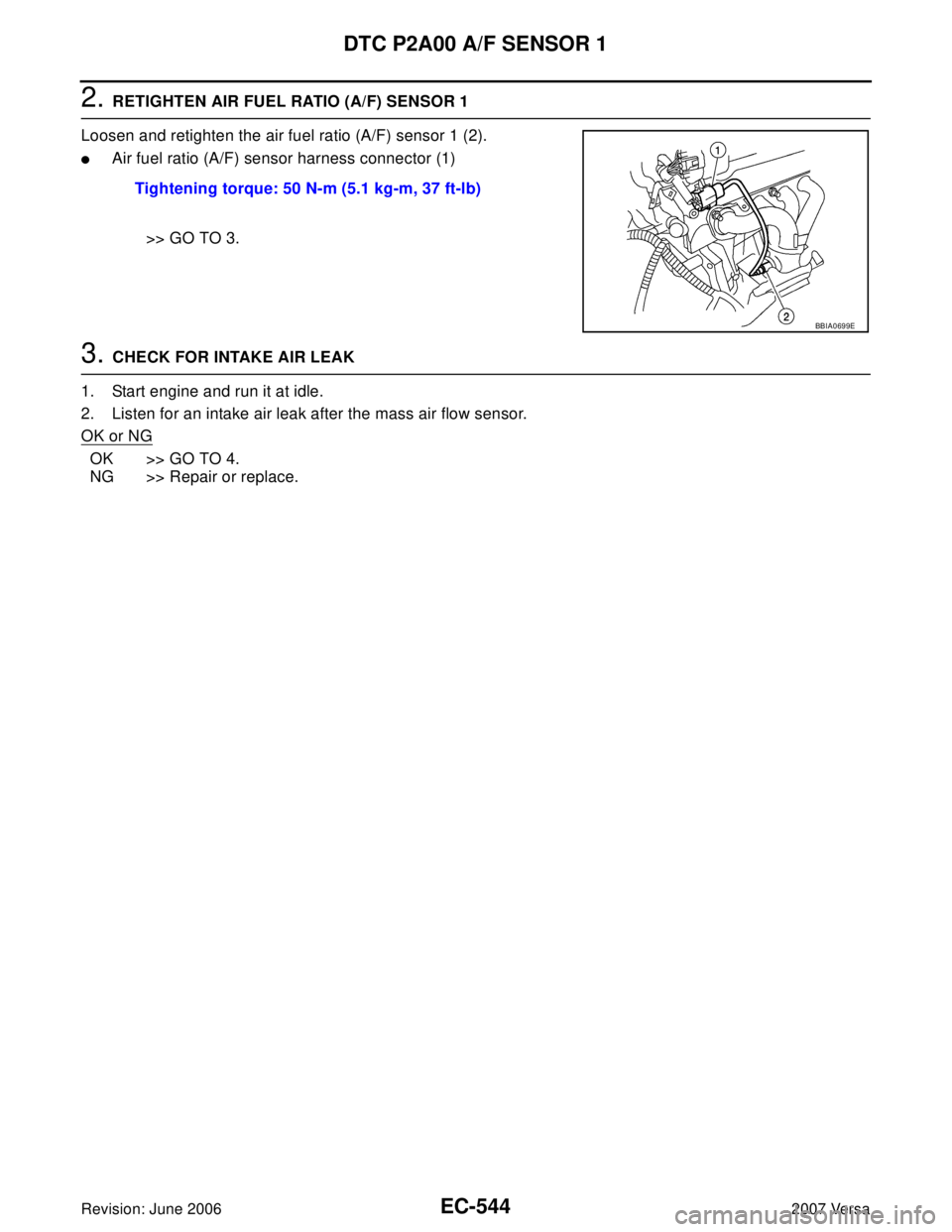
2. RETIGHTEN AIR FUEL RATIO (A/F) SENSOR 1
Loosen and retighten the air fuel ratio (A/F) sensor 1 (2).
�Air fuel ratio (A/F) sensor harness connector (1)
>> GO TO 3.
3. CHECK FOR INTAKE AIR LEAK
1. Start engine and run it at idle.
2. Listen for an intake air leak after the mass air flow sensor.
OK or NG
OK >> GO TO 4.
NG >> Repair or replace.Tightening torque: 50 N-m (5.1 kg-m, 37 ft-lb)
BBIA0699E
Page 1714 of 2896

DTC P2A00 A/F SENSOR 1
EC-545
C
D
E
F
G
H
I
J
K
L
MA
EC
Revision: June 20062007 Versa
4. CLEAR THE SELF-LEARNING DATA.
With CONSULT-II
1. Start engine and warm it up to normal operating temperature.
2. Select “SELF-LEARNING CONT” in “WORK SUPPORT” mode with CONSULT-II.
3. Clear the self-learning control coefficient by touching “CLEAR”.
4. Run engine for at least 10 minutes at idle speed.
Is the 1st trip DTC P0171 and P0172 detected?
Is it difficult to start engine?
Without CONSULT-II
1. Start engine and warm it up to normal operating temperature.
2. Turn ignition switch OFF.
3. Disconnect mass air flow sensor (1) harness connector.
4. Restart engine and let it idle for at least 5 seconds.
5. Stop engine and reconnect mass air flow sensor harness con-
nector.
6. Make sure DTC P0102 is displayed.
7. Erase the DTC memory. Refer to EC-60, "
HOW TO ERASE
EMISSION-RELATED DIAGNOSTIC INFORMATION" .
8. Make sure DTC P0000 is displayed.
9. Run engine for at least 10 minutes at idle speed.
Is the 1st trip DTC P0171 and P0172 detected?
Is it difficult to start engine?
Ye s o r N o
Yes >> Perform trouble diagnosis for DTC P0171 or P0172. Refer to EC-276, "DTC P0171 FUEL INJEC-
TION SYSTEM FUNCTION" or EC-284, "DTC P0172 FUEL INJECTION SYSTEM FUNCTION" .
No >> GO TO 5.
5. CHECK HARNESS CONNECTOR
1. Turn ignition switch OFF.
2. Disconnect A/F sensor 1 harness connector (1).
–Air fuel ratio (A/F) sensor (2)
3. Check harness connector for water.
OK or NG
OK >> GO TO 6.
NG >> Repair or replace harness connector.
PBIB2035E
BBIA0701E
Water should no exist.
BBIA0699E
Page 1715 of 2896
 SENSOR 1 POWER SUPPLY CIRCUIT
1. Turn ignition switch ON.
2. Check voltage between A/F sensor 1 terminal 4 and")
EC-546Revision: June 2006
DTC P2A00 A/F SENSOR 1
2007 Versa
6. CHECK AIR FUEL RATIO (A/F) SENSOR 1 POWER SUPPLY CIRCUIT
1. Turn ignition switch ON.
2. Check voltage between A/F sensor 1 terminal 4 and ground with
CONSULT-II or tester.
OK or NG
OK >> GO TO 8.
NG >> GO TO 7.
7. DETECT MALFUNCTIONING PART
Check the following.
�Harness connectors E8, F8
�Harness for open or short between A/F sensor 1 and fuse
>> Repair or replace harness or connectors.
8. CHECK A/F SENSOR 1 INPUT SIGNAL CIRCUIT FOR OPEN AND SHORT
1. Turn ignition switch OFF.
2. Disconnect ECM harness connector.
3. Check harness continuity between the following terminals. Refer to Wiring Diagram.
4. Check harness continuity between ECM terminals 49, 53 or A/F sensor 1 terminals 1, 2 and ground.
Refer to Wiring Diagram.
5. Also check harness for short to power.
OK or NG
OK >> GO TO 9.
NG >> Repair open circuit or short to ground or short to power in harness or connectors.
9. CHECK A/F SENSOR 1 HEATER
Refer to EC-165, "
Component Inspection" .
OK or NG
OK >> GO TO 10.
NG >> GO TO 11.
10. CHECK INTERMITTENT INCIDENT
Perform EC-143, "
TROUBLE DIAGNOSIS FOR INTERMITTENT INCIDENT" .
OK or NG
OK >> GO TO 11.
NG >> Repair or replace.Voltage: Battery voltage
PBIB3308E
A/F sensor 1 terminal ECM terminal
149
253
Continuity should exist.
Continuity should not exist.
Page 1716 of 2896
DTC P2A00 A/F SENSOR 1
EC-547
C
D
E
F
G
H
I
J
K
L
MA
EC
Revision: June 20062007 Versa
11 . REPLACE AIR FUEL RATIO (A/F) SENSOR 1
Replace air fuel ratio (A/F) sensor 1.
CAUTION:
�Discard any air fuel ratio (A/F) sensor which has been dropped from a height of more than 0.5 m
(19.7 in) onto a hard surface such as a concrete floor; use a new one.
�Before installing new air fuel ratio (A/F) sensor, clean exhaust system threads using Heated Oxy-
gen Sensor Thread Cleaner tool J-43897-18 or J-43897-12 and approved anti-seize lubricant.
>> GO TO 12.
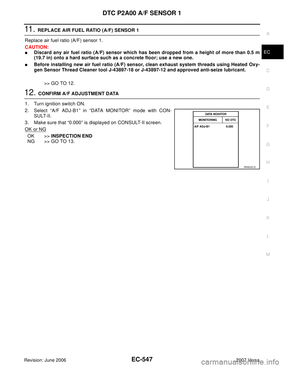
12. CONFIRM A/F ADJUSTMENT DATA
1. Turn ignition switch ON.
2. Select “A/F ADJ-B1” in “DATA MONITOR” mode with CON-
SULT-II.
3. Make sure that “0.000” is displayed on CONSULT-II screen.
OK or NG
OK >>INSPECTION END
NG >> GO TO 13.
PBIB3201E
Page 1717 of 2896

EC-548Revision: June 2006
DTC P2A00 A/F SENSOR 1
2007 Versa
13. CLEAR A/F ADJUSTMENT DATA
With CONSULT-II
1. Start engine and warm it up to normal operating temperature.
2. Select “SELF-LEARNING CONT” in “WORK SUPPORT” mode with CONSULT-II.
3. Clear the self-learning control coefficient by touching “CLEAR”.
Without CONSULT-II
1. Start engine and warm it up to normal operating temperature.
2. Turn ignition switch OFF.
3. Disconnect mass air flow sensor harness (1) connector.
4. Restart engine and let it idle for at least 5 seconds.
5. Stop engine and reconnect mass air flow sensor harness con-
nector.
6. Make sure DTC P0102 is displayed.
7. Erase the DTC memory. Refer to EC-60, "
HOW TO ERASE
EMISSION-RELATED DIAGNOSTIC INFORMATION" .
8. Make sure DTC P0000 is displayed.
>> GO TO 14.
14. CONFIRM A/F ADJUSTMENT DATA
1. Turn ignition switch OFF and then ON.
2. Select “A/F ADJ-B1” in “DATA MONITOR” mode with CON-
SULT-II.
3. Make sure that “0.000” is displayed on CONSULT-II screen.
>>INSPECTION END
Removal and InstallationUBS00QNV
AIR FUEL RATIO SENSOR
Refer to EM-21, "EXHAUST MANIFOLD" .
PBIB2035E
BBIA0701E
PBIB3201E
Page 1733 of 2896
EC-564Revision: June 2006
FUEL INJECTOR
2007 Versa
FUEL INJECTORPFP:16600
Component DescriptionUBS00PTO
The fuel injector is a small, precise solenoid valve. When the ECM
supplies a ground to the fuel injector circuit, the coil in the fuel injec-
tor is energized. The energized coil pulls the ball valve back and
allows fuel to flow through the fuel injector into the intake manifold.
The amount of fuel injected depends upon the injection pulse dura-
tion. Pulse duration is the length of time the fuel injector remains
open. The ECM controls the injection pulse duration based on
engine fuel needs.
CONSULT-II Reference Value in Data Monitor ModeUBS00PTP
Specification data are reference values.
PBIA9664J
MONITOR ITEM CONDITION SPECIFICATION
B/FUEL SCHDL See EC-133, "
TROUBLE DIAGNOSIS - SPECIFICATION VALUE" .
INJ PULSE-B1
�Engine: After warming up
�Air conditioner switch: OFF
�Shift lever: P or N (A/T, CVT),
Neutral (M/T)
�No loadIdle 2.0 - 3.0 msec
2,000 rpm 1.9 - 2.9 msec