Page 1817 of 2896
EM-8Revision: June 2006
PREPARATION
2007 Versa
ST16610001
(J-23907)
Pilot bushing pullerRemoving crankshaft pilot bushing
KV11103000
(—)
Pulley pullerRemoving crankshaft pulley
KV991J0050
(J-44626)
Air fuel sensor SocketLoosening or tightening air fuel ratio A/F
sensor
a: 22 mm (0.87 in)
KV10114400
(J-38365)
Heated oxygen sensor wrenchLoosening or tightening rear heated oxy-
gen sensor
a: 22 mm (0.87 in)
KV11105210
(J-44716)
Stopper plateSecuring diveplate and flywheel
KV10115600
(J-38958)
Valve oil seal driftInstalling valve oil seal
Use side A.
a: 20 (0.79) dia
b: 13 (0.51) dia.
c: 10.3 (0.406) dia
d: 8 (0.31) dia.
e: 10.7 (0.421)
f: 5 (0.20)
KV10115801
(—)
Oil filter wrenchRemoving and installing oil filter
a: 64.3 mm (2.531 in) Tool number
(Kent-Moore No.)
Tool nameDescription
NT045
NT676
LBIA0444E
NT636
ZZA0009D
S-NT603
S-NT375
Page 1842 of 2896
FUEL INJECTOR AND FUEL TUBE
EM-33
C
D
E
F
G
H
I
J
K
L
MA
EM
Revision: June 20062007 Versa
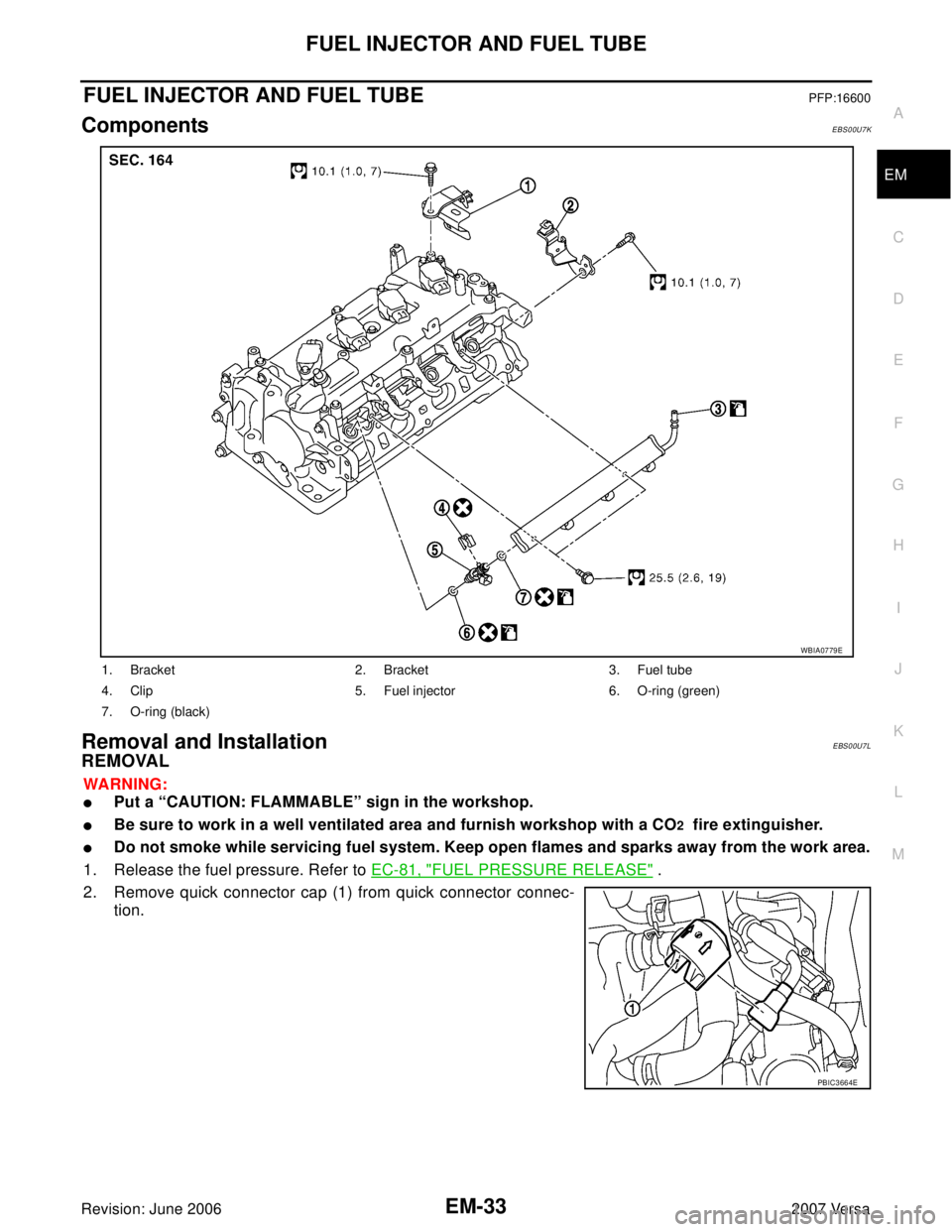
FUEL INJECTOR AND FUEL TUBEPFP:16600
ComponentsEBS00U7K
Removal and Installation EBS00U7L
REMOVAL
WA RN ING:
�Put a “CAUTION: FLAMMABLE” sign in the workshop.
�Be sure to work in a well ventilated area and furnish workshop with a CO2 fire extinguisher.
�Do not smoke while servicing fuel system. Keep open flames and sparks away from the work area.
1. Release the fuel pressure. Refer to EC-81, "
FUEL PRESSURE RELEASE" .
2. Remove quick connector cap (1) from quick connector connec-
tion.
1. Bracket 2. Bracket 3. Fuel tube
4. Clip 5. Fuel injector 6. O-ring (green)
7. O-ring (black)
WBIA0779E
PBIC3664E
Page 1843 of 2896

EM-34Revision: June 2006
FUEL INJECTOR AND FUEL TUBE
2007 Versa
3. Disconnect fuel feed hose from hose clamp.
NOTE:
There is no fuel return path.
4. With the sleeve side of quick connector release facing quick connector, install quick connector release
onto fuel tube.
5. Insert quick connector release into quick connector until sleeve
contacts and goes no further. Hold quick connector release on
that position.
CAUTION:
Inserting quick connector release hard will not disconnect
quick connector. Hold quick connector release where it
contacts and goes no further.
6. Draw and pull out quick connector straight from fuel tube.
CAUTION:
�Pull quick connector holding “A” position.
�Do not pull with lateral force applied. O-ring inside quick connector may be damaged.
�Prepare container and cloth beforehand as fuel will leak out.
�Avoid fire and sparks.
�Keep parts away from heat source. Especially, be careful when welding is performed around
them.
�Do not expose parts to battery electrolyte or other acids.
�Do not bend or twist connection between quick connector and fuel feed hose during installa-
tion/removal.
�To keep clean the connecting portion and to avoid dam-
age and foreign materials, cover them completely with
plastic bags or something similar.
7. Remove intake manifold. Refer to EM-18, "
INTAKE MANIFOLD" .
1 : Quick connector cap
PBIC3771E
KBIA0702E
PBIC2205E
Page 1844 of 2896

FUEL INJECTOR AND FUEL TUBE
EM-35
C
D
E
F
G
H
I
J
K
L
MA
EM
Revision: June 20062007 Versa
8. Remove fuel tube.
�Loosen bolts in reverse order as shown.
9. Remove the fuel tube and fuel injector assembly.
CAUTION:
�When removing, be careful to avoid any interference with fuel injector.
�Use a shop cloth to absorb any fuel leaks from fuel tube.
10. Remove fuel injector from fuel tube with the following procedure:
a. Open and remove clip.
b. Remove fuel injector from fuel tube by pulling straight.
CAUTION:
�Be careful with remaining fuel that may go out from fuel tube.
�Be careful not to damage fuel injector nozzle during removal.
�Never bump or drop fuel injector.
�Never disassemble fuel injector.
INSTALLATION
1. Note the following, and install O-rings to fuel injector.
CAUTION:
�Upper and lower O-rings are different. Be careful not to confuse them.
�Handle O-ring with bare hands. Never wear gloves.
�Lubricate O-ring with new engine oil.
�Never clean O-ring with solvent.
�Make sure that O-ring and its mating part are free of foreign material.
�When installing O-ring, be careful not to scratch it with tool or fingernails. Also be careful not to
twist or stretch O-ring. If O-ring was stretched while it was being attached, never insert it quickly
into fuel tube.
�Insert O-ring straight into fuel tube. Never twist it.
: Engine front
PBIC3154J
Fuel tube side : Black
Nozzle side : Green
Page 1845 of 2896
 to fuel tube (1) with the following proce-
dure:
a. Insert clip (2) into clip groove (F) on fuel injector.")
EM-36Revision: June 2006
FUEL INJECTOR AND FUEL TUBE
2007 Versa
2. Install fuel injector (4) to fuel tube (1) with the following proce-
dure:
a. Insert clip (2) into clip groove (F) on fuel injector.
�Insert clip so that protrusion (G) of fuel injector matches cut-
out (D) of clip.
CAUTION:
�Never reuse clip. Replace it with a new one.
�Be careful to keep clip from interfering with O-ring. If
interference occurs, replace O-ring.
b. Insert fuel injector into fuel tube with clip attached.
�Insert it while matching it to the axial center.
�Insert fuel injector so that protrusion (B) of fuel tube matches
cut-out (C) of clip.
�Make sure that fuel tube flange (A) is securely fixed in flange
fixing groove (E) on clip.
c. Make sure that installation is complete by making sure that fuel
injector does not rotate or come off.
3. Set fuel tube and fuel injector assembly at its position for installation on cylinder head.
CAUTION:
For installation, be careful not to interfere with fuel injector nozzle.
4. Tighten bolts in numerical order as shown.
5. Installation of the remaining components is in the reverse order of removal.
3 : O–ring (black)
5 : O–ring (green)
PBIC3155J
: Engine front
PBIC3154J
Page 1856 of 2896

CAMSHAFT
EM-47
C
D
E
F
G
H
I
J
K
L
MA
EM
Revision: June 20062007 Versa
CAMSHAFTPFP:13001
ComponentsEBS00U7O
Removal and InstallationEBS00U7P
REMOVAL
WA RN ING:
�Put a “CAUTION: FLAMMABLE” sign in the workshop.
�Be sure to work in a well ventilated area and furnish workshop with a CO2 fire extinguisher.
�Do not smoke while servicing fuel system. Keep open flames and sparks away from the work area.
1. Release the fuel pressure. Refer to EC-81, "
FUEL PRESSURE RELEASE" .
2. Disconnect negative battery cable. Refer to SC-9, "
Removal and Installation" .
3. Remove front RH wheel. Refer to WT-6, "
ROAD WHEEL TIRE ASSEMBLY" .
4. Remove front fender protector (RH). Refer to EI-22, "
FENDER PROTECTOR" .
5. Drain engine coolant. Refer to CO-8, "
ENGINE COOLANT" .
NOTE:
Perform this step when engine is cold.
6. Remove the following parts.
�Intake manifold; Refer to EM-18, "INTAKE MANIFOLD" .
1. O-ring 2. Camshaft position sensor (PHASE) 3. Camshaft bracket
4. Camshaft sprocket (EXH) 5. Camshaft sprocket (INT) 6. Camshaft (EXH)
7. Camshaft (INT) 8. Valve lifter (EXH) 9. Valve lifter (INT)
10. Cylinder head
A. Refer to EM-51
.
PBIC4589E
Page 1857 of 2896

EM-48Revision: June 2006
CAMSHAFT
2007 Versa
�Rocker cover; Refer toEM-30, "IGNITION COIL, SPARK PLUG AND ROCKER COVER" .
�Fuel tube and fuel injector assembly; Refer to EM-33, "FUEL INJECTOR AND FUEL TUBE" .
�Front cover, timing chain and related parts; Refer to EM-37, "TIMING CHAIN" .
7. Remove camshaft position sensor (PHASE) from camshaft bracket.
CAUTION:
�Handle carefully to avoid dropping and shocks.
�Never disassemble.
�Never allow metal powder to adhere to magnetic part at sensor tip.
�Never place sensor in a location where it is exposed to magnetism.
8. Put the matching mark (A) on the camshaft sprocket (INT) (2)
and the camshaft bracket (1) as shown.
NOTE:
It prevents the knock pin of the camshaft (INT) from engaging
with the incorrect pin hole when installing the camshaft sprocket
(INT).
9. Remove camshaft sprockets (INT) (1) and (EXH) (2).
�Secure hexagonal part (A) of camshaft with a wrench. Loosen
camshaft sprocket bolts and remove camshaft sprocket.
CAUTION:
�Never rotate crankshaft or camshaft while timing chain
is removed. It causes interference between valve and
piston.
�Never loosen the bolts with securing anything other
than the camshaft hexagonal part or with tensioning
the timing chain.
10. Loosen bolts in reverse order as shown.
11. Cut liquid gasket by prying the position ( ) shown, and then
remove the camshaft bracket.
CAUTION:
�Be careful not to damage the mating surface.
�A more adhesive liquid gasket is applied compared to
previous types when shipped, so it should not be forced
off the position not specified.
: Engine front
PBIC3992J
PBIC3454J
: Engine front
PBIC3176J
: Engine front
PBIC3358J
Page 1863 of 2896
 (2).
NOTE:
Secure the hexagonal part (A) of camshaft (EXH) using wrench
to tighten bolt.
11. Install timing chain and r")
EM-54Revision: June 2006
CAMSHAFT
2007 Versa
10. Install camshaft sprocket (EXH) (2).
NOTE:
Secure the hexagonal part (A) of camshaft (EXH) using wrench
to tighten bolt.
11. Install timing chain and related parts. Refer to EM-37, "
TIMING CHAIN" .
12. Inspect and adjust valve clearance. Refer to EM-55, "
Valve Clearance" .
13. Installation of the remaining components is in the reverse order of removal.
INSPECTION AFTER INSTALLATION
The following are procedures for checking fluids leak, lubricates leak.
�Before starting engine, check oil/fluid levels including engine coolant and engine oil. If less than required
quantity, fill to the specified level. Refer to GI-46, "
Recommended Chemical Products and Sealants" .
�Use procedure below to check for fuel leakage.
–Turn ignition switch “ON” (with engine stopped). With fuel pressure applied to fuel piping, check for fuel
leakage at connection points.
–Start engine. With engine speed increased, check again for fuel leakage at connection points.
�Run engine to check for unusual noise and vibration.
NOTE:
If hydraulic pressure inside timing chain tensioner drops after removal/installation, slack in the guide may
generate a pounding noise during and just after engine start. However, this is normal. Noise will stop after
hydraulic pressure rises.
�Warm up engine thoroughly to make sure there is no leakage of fuel, or any oil/fluids including engine oil
and engine coolant.
�Bleed air from lines and hoses of applicable lines, such as in cooling system.
�After cooling down engine, again check oil/fluid levels including engine oil and engine coolant. Refill to the
specified level, if necessary.
Summary of the inspection items:
* Transmission/transaxle/CVT fluid, power steering fluid, brake fluid, etc.
Inspection of Camshaft Sprocket (INT) Oil Groove
CAUTION:
�Perform this inspection only when DTC P0011 is detected in self-diagnostic results of CONSULT-II
and it is directed according to inspection procedure of EC section. Refer to EC-47, "
ON BOARD
DIAGNOSTIC (OBD) SYSTEM" .
�Check when engine is cold so as to prevent burns from the splashing engine oil.
1. Check engine oil level. Refer to LU-5, "
ENGINE OIL LEVEL" .
2. Perform the following procedure so as to prevent the engine from being unintentionally started while
checking.
a. Remove intake manifold. Refer to EM-18, "
Components" .
1 : Camshaft sprocket (INT)
Camshaft sprocket
bolt (EXH): 88.2 N·m (9.0 kg-m, 65 ft-lb)
PBIC3454J
Item Before starting engine Engine running After engine stopped
Engine coolant Level Leakage Level
Engine oil Level Leakage Level
Other oils and fluid* Level Leakage Level
Fuel Leakage Leakage Leakage
Exhaust gases — Leakage —

Pilot bushing pullerRemoving crankshaft pilot bushing
KV11103000
(—)
Pulley pullerRemoving crankshaft pulley
KV991J0050
(J-44626)")