Page 1963 of 2896
 and fuel feed hose quick
connector (B).
�Fuel feed hose (1)
�⇐ :")
FL-6Revision: June 2006
FUEL LEVEL SENSOR UNIT, FUEL FILTER AND FUEL PUMP ASSEMBLY
2007 Versa
6. Disconnect electrical connector (A) and fuel feed hose quick
connector (B).
�Fuel feed hose (1)
�⇐ : Vehicle front
�Disconnect the quick connector using the following procedure.
–Hold the sides of the connector, push in tabs and pull out the
tube.
–If quick connector and tube on fuel pump assembly are stuck,
push and pull several times until they move. Disconnect them
by pulling.
CAUTION:
�The tube can be removed when the tabs are completely
depressed. Do not twist it more than necessary.
�Do not use any tools to remove the quick connector.
�Keep resin tube away from heat. Be especially careful
when welding near the resin tube.
�Prevent acid liquid such as battery electrolyte, from getting on resin tube.
�Do not bend or twist resin tube during installation and removal.
�To keep the connecting portion clean, free of foreign
materials and to avoid damage, cover them completely
with plastic bags or something similar.
�Do not insert plug to prevent damage to O-ring in quick
connector.
7. Remove the lock ring using Tool as shown.
WBIA0782E
SF E5 62 A
PBIC0163E
Tool number : KV991J0090 (J-46214)
WBIA0284E
Page 1964 of 2896
.
CAUTIO")
FUEL LEVEL SENSOR UNIT, FUEL FILTER AND FUEL PUMP ASSEMBLY
FL-7
C
D
E
F
G
H
I
J
K
L
MA
FL
Revision: June 20062007 Versa
8. Remove fuel level sensor unit, fuel filter and fuel pump assembly
(1).
CAUTION:
�Do not bend float arm during removal.
�Do not allow foreign materials to fall into fuel tank. Use a
lint free cloth when handling components.
�Avoid impacts such as dropping when handling compo-
nents.
INSPECTION AFTER REMOVAL
Make sure that the fuel level sensor unit, fuel filter and fuel pump is free from defects and foreign materials.
INSTALLATION
Installation is in the reverse order of removal.
Fuel Level Sensor Unit, Fuel Filter and Fuel Pump Assembly
1. Install O-ring to fuel tank without twisting.
2. Install fuel level sensor unit with aligning mating marks (A) on
fuel tank and fuel level sensor unit as shown.
�Turn the lock ring (1) until the lock ring is fully rotated into the
fuel tank lock tabs (A) as shown.
Quick Connector
Connect fuel feed tube quick connector using the following procedure.
1. Check the connection for damage or any foreign materials.
2. Align the connector with the tube, then insert the connector straight into the tube until a “click” sound is
heard.
3. After connecting, make sure that the connection is secure using the following procedure.
�Visually confirm that the two retainer tabs are secured to the connector.
PBIC3780E
: Vehicle front
PBIC4732E
WBIA0783E
Page 1965 of 2896
FL-8Revision: June 2006
FUEL LEVEL SENSOR UNIT, FUEL FILTER AND FUEL PUMP ASSEMBLY
2007 Versa
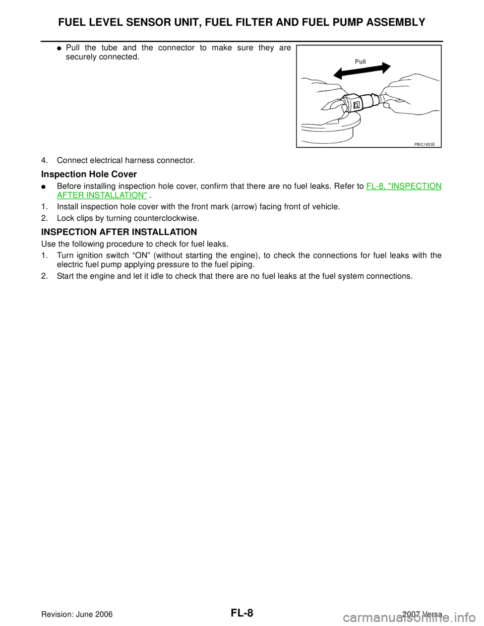
�Pull the tube and the connector to make sure they are
securely connected.
4. Connect electrical harness connector.
Inspection Hole Cover
�Before installing inspection hole cover, confirm that there are no fuel leaks. Refer to FL-8, "INSPECTION
AFTER INSTALLATION" .
1. Install inspection hole cover with the front mark (arrow) facing front of vehicle.
2. Lock clips by turning counterclockwise.
INSPECTION AFTER INSTALLATION
Use the following procedure to check for fuel leaks.
1. Turn ignition switch “ON” (without starting the engine), to check the connections for fuel leaks with the
electric fuel pump applying pressure to the fuel piping.
2. Start the engine and let it idle to check that there are no fuel leaks at the fuel system connections.
PBIC1653E
Page 1966 of 2896

FUEL TANK
FL-9
C
D
E
F
G
H
I
J
K
L
MA
FL
Revision: June 20062007 Versa
FUEL TANKPFP:17202
ComponentsEBS00TSL
Removal and InstallationEBS00TSM
REMOVAL
WA RN ING:
Be sure to read “General Precautions” when working on the fuel system. Refer to FL-4, "
General Pre-
cautions" .
1. Drain fuel from fuel tank if necessary. Refer to FL-5, "
REMOVAL" .
CAUTION:
�Because fuel tank becomes unstable when installing/removing, fuel should be drained if the
level exceeds specification FL-5, "
Removal and Installation" .
�Situate vehicle on a flat and solid surface.
2. Open fuel door and unscrew the fuel filler cap to release the pressure inside the fuel tank.
3. Release the fuel pressure from the fuel lines. Refer to EC-81, "
FUEL PRESSURE RELEASE" .
4. Remove rear seat bottom. Refer to SE-14, "
REAR SEAT" .
5. Turn the three retainers 90° in a clockwise direction and remove the fuel pump inspection hole cover.
1. Lock ring 2. Fuel pump 3. O-ring
4. Fuel tank 5. Fuel tank band (LH) 6. Fuel tank band (RH)
7. EVAP hose 8. Hose clamp 9. Fuel filler hose
10. Hose clamp 11. Fuel filler pipe shield 12. Fuel filler tube
13. Grommet 14. Fuel filler cap⇐Front of vehicle
WCIA0591E
Page 1967 of 2896
 and fuel feed hose quick connec-
tor (B).
�Fuel feed hose (1)
�⇐ : Vehicle front
�Disconnect the quick connector usi")
FL-10Revision: June 2006
FUEL TANK
2007 Versa
Disconnect electrical connector (A) and fuel feed hose quick connec-
tor (B).
�Fuel feed hose (1)
�⇐ : Vehicle front
�Disconnect the quick connector using the following procedure.
–Hold the sides of the connector, push in tabs and pull out the
tube.
–If quick connector and tube on fuel pump assembly are stuck,
push and pull several times until they move. Disconnect them by
pulling.
CAUTION:
�The tube can be removed when the tabs are completely
depressed. Do not twist it more than necessary.
�Do not use any tools to remove the quick connector.
�Keep resin tube away from heat. Be especially careful
when welding near the resin tube.
�Prevent acid liquid such as battery electrolyte, from getting on resin tube.
�Do not bend or twist resin tube during installation and removal.
�To keep the connecting portion clean, free of foreign
materials and to avoid damage, cover them completely
with plastic bags or something similar.
�Do not insert plug to prevent damage to O-ring in quick
connector.
6. Remove center exhaust tube. Refer to EX-3, "
EXHAUST SYSTEM" .
7. Remove exhaust heat shields.
8. Disconnect parking brake cables (1) from the lower surface of
fuel tank and axle and position the parking brake cables (1) out
of the way.
WBIA0782E
SF E5 62 A
PBIC0163E
PBIC3786E
Page 1968 of 2896
 from rear axle (2).
10. Loosen fuel filler hose clamp (3) and remove fuel filler hose (1)
fro")
FUEL TANK
FL-11
C
D
E
F
G
H
I
J
K
L
MA
FL
Revision: June 20062007 Versa
9. Remove brake tube protector (1) from rear axle (2).
10. Loosen fuel filler hose clamp (3) and remove fuel filler hose (1)
from fuel tank (2).
CAUTION:
Do not remove fuel filler hose (1) from fuel filler tube. Do not
allow contact with the suspension during installation. When
removing fuel filler hose (1) at the fuel filler tube, mark com-
ponents for alignment.
11. Remove vent hose (1) and EVAP hose (2) at rear of fuel tank.
�Disconnect vent hose and EVAP hose quick connectors using
the following procedures.
a. Pinch retaining tabs (A) of vent hose quick connector and
remove vent hose (1).
b. Slide sleeve (B) of EVAP hose quick connector and remove
EVAP hose (2).
�If hoses are stuck, push and pull several times until they move
freely, and disconnect.
CAUTION:
�The tube can be removed when the tabs are completely depressed. Do not twist it more than
necessary.
�Do not use any tools to remove the quick connector.
�Keep the resin tube away from heat. Be especially careful when welding near the tube.
�Prevent acid liquid such as battery electrolyte, from getting on the resin tube.
�Do not bend or twist the tube during installation and removal.
�Do not insert plug that may cause damage to O-ring in quick connector.
�To keep the connecting portion clean and to avoid dam-
age and foreign materials, cover them completely with
plastic bags or something similar.
WBIA0764E
WBIA0765E
WBIA0766E
PBIC0163E
Page 1969 of 2896
 with transmission jack (A).
CAUTION:
Securely support the fuel tank with a suitable tool (B).
13. Remove fuel tank ban")
FL-12Revision: June 2006
FUEL TANK
2007 Versa
12. Support center of fuel tank (1) with transmission jack (A).
CAUTION:
Securely support the fuel tank with a suitable tool (B).
13. Remove fuel tank bands (RH and LH).
14. Lower transmission jack carefully to remove fuel tank while sup-
porting it by hand.
CAUTION:
Fuel tank may be in an unstable position because of the
shape of fuel tank bottom. Be sure to support tank securely.
INSTALLATION
Installation is in the reverse order of removal.
EVAP Canister
1. Check the connection for damage or any foreign materials.
2. Align the connector with the tube, then insert the connector straight into the tube until a “click” sound is
heard.
3. After connecting, make sure that the connection is secure.
�Pull the tube and the connector to make sure they are securely connected.
Fuel Tank Band
�Install them in the proper position by referring to the identification stamp mark “R” and “L” on the end.
Fuel Filler Hose
�Insert fuel filler hose to the length below.
�Be sure hose clamp is not placed on swelled area of fuel filler tube.
EVAP Hose
1. Check connections for damage or foreign material.
2. Align the matching quick connector (A) with the center of EVAP
hose (1), and insert quick connector (A) straight until it clicks.
3. After connecting, pull on quick connector (A) and EVAP hose (1)
by hand. Make sure connections are secure.
INSPECTION AFTER INSTALLATION
Use the following procedure to check for fuel leaks.
1. Turn ignition switch “ON” (without starting the engine), to check the connections for fuel leaks with the
electric fuel pump applying pressure to the fuel piping.
2. Start the engine and let it idle to check that there are no fuel leaks at the fuel system connections.
PBIC3792E
: 35mm (1.38 in)
WBIA0767E
Page 1970 of 2896
SERVICE DATA AND SPECIFICATIONS (SDS)
FL-13
C
D
E
F
G
H
I
J
K
L
MA
FL
Revision: June 20062007 Versa
SERVICE DATA AND SPECIFICATIONS (SDS)PFP:00030
Standard and LimitEBS00TSN
FUEL TANK
Unit: (US gal, Imp gal)
Fuel tank capacity50.0 (13 1/4, 11)
Fuel recommendation Refer to MA-11, "
RECOMMENDED FLUIDS AND LUBRICANTS"

FL-13
C
D
E
F
G
H
I
J
K
L
MA
FL
Revision: June 20062007 Versa
SERVICE DATA AND SPECIFICATIONS (SDS)PFP:00030
Standard and LimitEBS00TSN
FUEL TANK
Unit: (US gal,")