Page 942 of 2896

TROUBLE DIAGNOSIS
CVT-45
D
E
F
G
H
I
J
K
L
MA
B
CVT
Revision: June 20062007 Versa
LINE PRESSURE TEST
Line Pressure Test Port
Line Pressure Test Procedure
1. Inspect the amount of engine oil and replenish if necessary.
2. Drive the car for about 10 minutes to warm it up so that the CVT fluid reaches in the range of 50 to 80°C
(122 to 176°F), then inspect the amount of CVT fluid and replenish if necessary.
NOTE:
The CVT fluid temperature rises in the range of 50 - 80°C (122 - 176°F) during 10 minutes of driving.
3. After warming up CVT, remove the oil pressure detection plug and install the oil pressure gauge [special
service tool: - (OTC3492)].
CAUTION:
When using the oil pressure gauge, be sure to use the O-ring attached to the oil pressure detec-
tion plug.
4. Securely engage the parking brake so that the tires do not turn.
5. Start the engine, and then measure the line pressure at both idle
and the stall speed.
CAUTION:
�Keep the brake pedal pressed all the way down during
measurement.
�When measuring the line pressure at the stall speed,
refer to CVT-43, "
STALL TEST" .
6. After the measurements are complete, install the oil pressure
detection plug and tighten to the specified torque below.
CAUTION:
�Do not reuse O-ring.
�Apply CVT fluid to O-ring.
SCIA6184E
SAT5 1 3G
: 7.5 N·m (0.77 kg-m, 66 in-lb)SAT4 9 3G
Page 1935 of 2896

FAX-4
NOISE, VIBRATION AND HARSHNESS (NVH) TROUBLESHOOTING
Revision: June 20062007 Versa
NOISE, VIBRATION AND HARSHNESS (NVH) TROUBLESHOOTINGPFP:00003
NVH Troubleshooting ChartEDS003QP
Use chart below to help you find the cause of the symptom. If necessary, repair or replace these parts.
×: ApplicableReference page
—
—
—
FA X - 5—
FA X - 5
FSU-5, "
NVH Troubleshooting Chart
"
Refer to Front axle in this chart.
WT-4, "
NVH Troubleshooting Chart
"
WT-4, "
NVH Troubleshooting Chart
"
Refer to DRIVE SHAFT in this chart.
BR-5, "
NVH Troubleshooting Chart
"
PS-5, "
NVH Trouble Shooting Chart
"
Possible cause and SUSPECTED PARTS
Excessive joint angle
Joint sliding resistance
Imbalance
Improper installation, looseness
Parts interference
Wheel bearing damage
FRONT SUSPENSION
FRONT AXLE
TIRES
ROAD WHEELS
DRIVE SHAFT
BRAKES
STEERING
SymptomDRIVE
SHAFTNoise×× ××××× ××
Shake× × ××××× ××
FRONT
AXLENoise×××× ×××××
Shake×××× ×××××
Vibration×××××××
Shimmy×××××××
Judder× × ×× ××
Poor quality ride or handling×××××
Page 1973 of 2896
GI-2Revision: June 20062007 Versa VEHICLE IDENTIFICATION NUMBER
ARRANGEMENT ................................................. 48
IDENTIFICATION PLATE .................................... 49
ENGINE SERIAL NUMBER ................................ 49
AUTOMATIC TRANSAXLE NUMBER ................. 49
MANUAL TRANSAXLE NUMBER ....................... 49CVT NUMBER .....................................................50
Dimensions .............................................................50
Wheels & Tires ........................................................50
TERMINOLOGY ........................................................51
SAE J1930 Terminology List ...................................51
Page 2015 of 2896

GI-44
TOW TRUCK TOWING
Revision: June 20062007 Versa
TOW TRUCK TOWINGPFP:00000
To w Tr u c k To w i n gEAS00201
CAUTION:
�All applicable local laws regarding the towing operation must be obeyed.
�It is necessary to use proper towing equipment to avoid possible damage to the vehicle during
towing operation. Towing is in accordance with Towing Procedure Manual at dealer.
�Always attach safety chains before towing.
�When towing, make sure that the transmission, steering system and power train are in good order.
If any unit is damaged, dollies must be used.
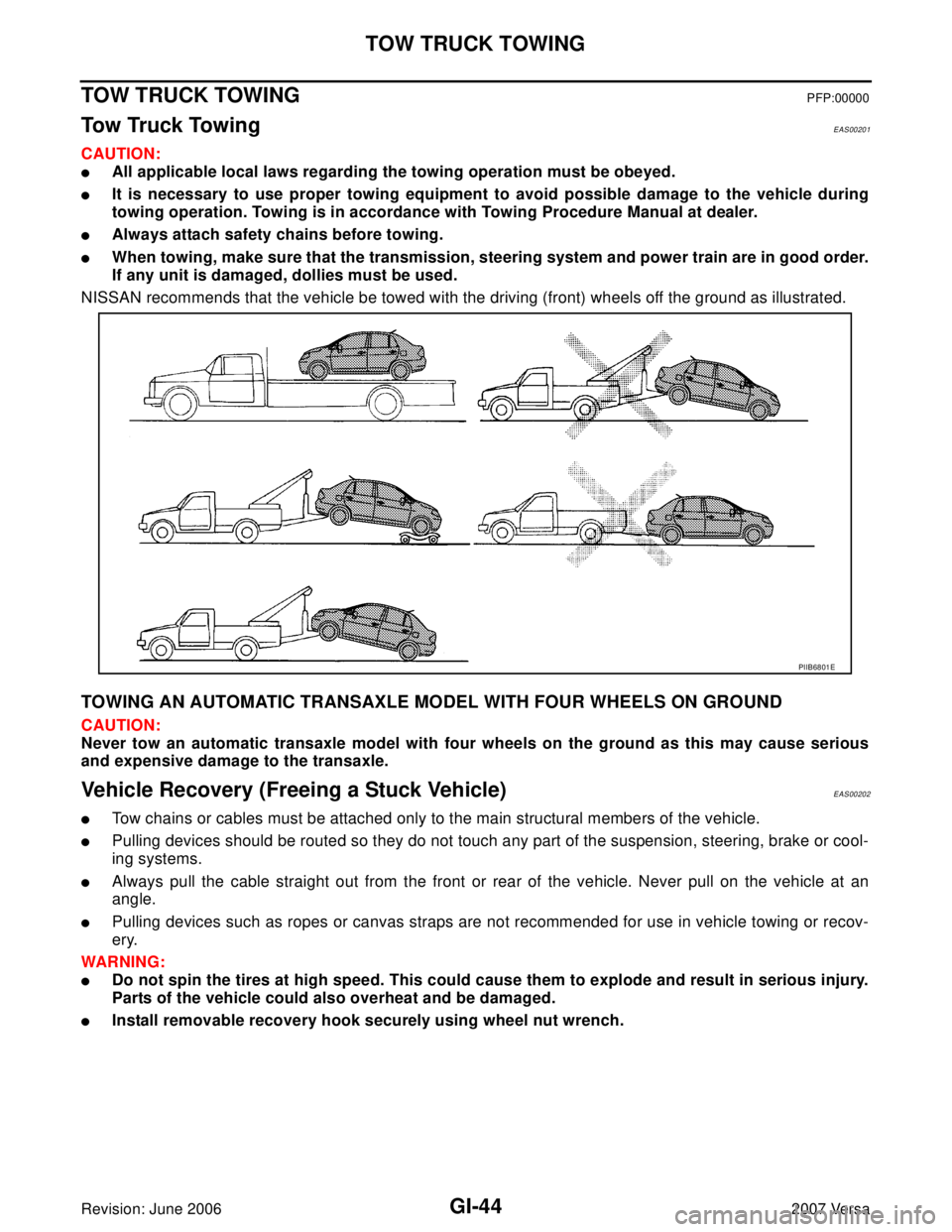
NISSAN recommends that the vehicle be towed with the driving (front) wheels off the ground as illustrated.
TOWING AN AUTOMATIC TRANSAXLE MODEL WITH FOUR WHEELS ON GROUND
CAUTION:
Never tow an automatic transaxle model with four wheels on the ground as this may cause serious
and expensive damage to the transaxle.
Vehicle Recovery (Freeing a Stuck Vehicle)EAS00202
�Tow chains or cables must be attached only to the main structural members of the vehicle.
�Pulling devices should be routed so they do not touch any part of the suspension, steering, brake or cool-
ing systems.
�Always pull the cable straight out from the front or rear of the vehicle. Never pull on the vehicle at an
angle.
�Pulling devices such as ropes or canvas straps are not recommended for use in vehicle towing or recov-
ery.
WAR NIN G:
�Do not spin the tires at high speed. This could cause them to explode and result in serious injury.
Parts of the vehicle could also overheat and be damaged.
�Install removable recovery hook securely using wheel nut wrench.
PIIB6801E
Page 2021 of 2896
GI-50
IDENTIFICATION INFORMATION
Revision: June 20062007 Versa
CVT NUMBER
Dimensions EAS00205
Unit: mm (in)
Wheels & Tires EAS00206
LAIA0074E
Overall length4,295 (169.1)
Overall width1,694.2 (66.7)
Overall height1,534.1 (60.4)
Front tread1,480 (58.3)
Rear tread1,485 (58.5)
Wheelbase2,599.9 (102.4)
Road wheel
Size15 x 5.5 JJ
Offset mm (in) 40 (1.57)
Tire s ize
Conventional185/65 R15
SpareT125/70D15
Page 2231 of 2896
HEADLAMP (FOR USA)
LT-23
C
D
E
F
G
H
I
J
L
MA
B
LT
Revision: June 20062007 Versa
3. CHECKING CAN COMMUNICATIONS BETWEEN BCM AND IPDM E/R
Select “BCM” on CONSULT-II, and perform self-diagnosis for
“BCM”.
Display of self
-diagnosis results
NO DTC>> Replace IPDM E/R. Refer to PG-29, "Removal and
Installation of IPDM E/R" .
CAN COMM CIRCUIT>> Refer to LAN-44, "
TROUBLE DIAGNO-
SIS" .
Aiming AdjustmentEKS00IMG
PREPARATION BEFORE ADJUSTING
Before performing aiming adjustment, check the following.
1. Keep all tires inflated to correct pressures.
2. Place vehicle on level surface.
3. Set that there is no-load in vehicle other than the driver (or equivalent weight placed in driver's position).
Coolant, engine oil filled up to correct level and full fuel tank.
LOW BEAM AND HIGH BEAM
1. Turn headlamp low beam ON.
2. Use adjusting screw to perform aiming adjustment.
PKIA7627E
1. Headlamp A. Inner and outer adjustment B. Adjusting screw
WKIA5417E
Page 2245 of 2896

HEADLAMP (FOR CANADA) - DAYTIME LIGHT SYSTEM -
LT-37
C
D
E
F
G
H
I
J
L
MA
B
LT
Revision: June 20062007 Versa
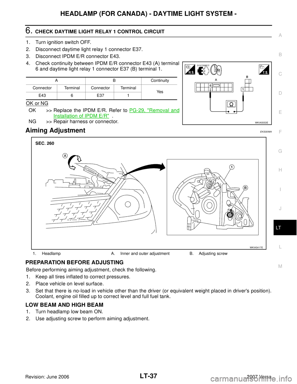
6. CHECK DAYTIME LIGHT RELAY 1 CONTROL CIRCUIT
1. Turn ignition switch OFF.
2. Disconnect daytime light relay 1 connector E37.
3. Disconnect IPDM E/R connector E43.
4. Check continuity between IPDM E/R connector E43 (A) terminal
6 and daytime light relay 1 connector E37 (B) terminal 1.
OK or NG
OK >> Replace the IPDM E/R. Refer to PG-29, "Removal and
Installation of IPDM E/R" .
NG >> Repair harness or connector.
Aiming AdjustmentEKS00IM4
PREPARATION BEFORE ADJUSTING
Before performing aiming adjustment, check the following.
1. Keep all tires inflated to correct pressures.
2. Place vehicle on level surface.
3. Set that there is no-load in vehicle other than the driver (or equivalent weight placed in driver's position).
Coolant, engine oil filled up to correct level and full fuel tank.
LOW BEAM AND HIGH BEAM
1. Turn headlamp low beam ON.
2. Use adjusting screw to perform aiming adjustment.
A B Continuity
Connector Terminal Connector Terminal
Ye s
E43 6 E37 1
WKIA5553E
1. Headlamp A. Inner and outer adjustment B. Adjusting screw
WKIA5417E
Page 2257 of 2896

FRONT FOG LAMP
LT-49
C
D
E
F
G
H
I
J
L
MA
B
LT
Revision: June 20062007 Versa
Aiming AdjustmentEKS00HXJ
The front fog lamp is a semi-sealed beam type which uses a replaceable halogen bulb. Before performing
aiming adjustment, make sure of the following.
�Keep all tires inflated to correct pressure.
�Place vehicle on level surface.
�Set that there is no-load in vehicle other than the driver (or equivalent weight placed in driver’s position).
Coolant, engine oil filled up to correct level and full fuel tank.
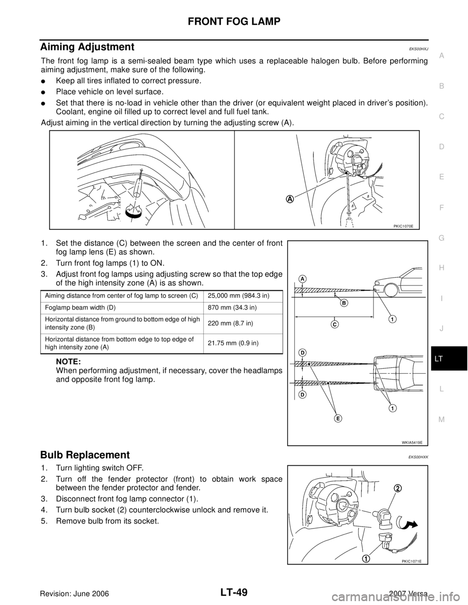
Adjust aiming in the vertical direction by turning the adjusting screw (A).
1. Set the distance (C) between the screen and the center of front
fog lamp lens (E) as shown.
2. Turn front fog lamps (1) to ON.
3. Adjust front fog lamps using adjusting screw so that the top edge
of the high intensity zone (A) is as shown.
NOTE:
When performing adjustment, if necessary, cover the headlamps
and opposite front fog lamp.
Bulb ReplacementEKS00HXK
1. Turn lighting switch OFF.
2. Turn off the fender protector (front) to obtain work space
between the fender protector and fender.
3. Disconnect front fog lamp connector (1).
4. Turn bulb socket (2) counterclockwise unlock and remove it.
5. Remove bulb from its socket.
PKIC1070E
Aiming distance from center of fog lamp to screen (C) 25,000 mm (984.3 in)
Foglamp beam width (D) 870 mm (34.3 in)
Horizontal distance from ground to bottom edge of high
intensity zone (B)220 mm (8.7 in)
Horizontal distance from bottom edge to top edge of
high intensity zone (A)21.75 mm (0.9 in)
WKIA5419E
PKIC1071E