Page 88 of 2896

TROUBLE DIAGNOSIS
AT-75
D
E
F
G
H
I
J
K
L
MA
B
AT
Revision: June 20062007 Versa
OthersVehicle moves when
changing into “P”
position or parking
gear does not disen-
gage when shifted out
of “P” position.ON vehicle 1. Control cable adjustmentAT- 2 3 3
OFF vehicle 2. Parking componentsAT- 2 5 7
Vehicle runs in “N”
position.
AT- 2 0 1
ON vehicle 1. Control cable adjustmentAT- 2 3 3
OFF vehicle2. Forward clutchAT- 3 2 03. Reverse clutchAT- 3 0 9
4. Overrun clutchAT- 3 2 0
Vehicle braked when
shifting into “R” posi-
tion.ON vehicle1. A/T fluid levelAT- 1 6
2. Control cable adjustmentAT- 2 3 3
3. Line pressure testAT- 5 6
4. Line pressure solenoid valveAT- 1 4 5
5. Control valve assemblyAT- 2 4 2
OFF vehicle6. High clutchAT- 3 1 47. Brake band AT- 3 4 3
8. Forward clutchAT- 3 2 0
9. Overrun clutchAT- 3 2 0
Excessive creep. ON vehicle 1. Engine idling speedEC-75
Engine stops when
shifting lever into “R”,
“D”, “2” and “1” posi-
tions.ON vehicle1. Engine idling speedEC-752. A/T fluid levelAT- 1 6
3. Torque converter clutch solenoid valveAT- 1 3 4
4. Control valve assemblyAT- 2 4 2
OFF vehicle 5. Torque converterAT- 2 6 8
Vehicle braked by
gear change from D
1
to D
2 .ON vehicle 1. A/T fluid levelAT- 1 6OFF vehicle2. Reverse clutchAT- 3 0 93. Low & reverse brakeAT- 3 2 7
4. High clutchAT- 3 1 4
5. Low one-way clutchAT- 2 6 8
Vehicle braked by
gear change from D
2
to D
3 .ON vehicle 1. A/T fluid levelAT- 1 6OFF vehicle 2. Brake bandAT- 3 4 3
Vehicle braked by
gear change from D
3
to D
4 .ON vehicle 1. A/T fluid levelAT- 1 6OFF vehicle2. Overrun clutchAT- 3 2 03. Forward one-way clutchAT- 3 3 2
4. Reverse clutchAT- 3 0 9
Items Symptom Condition Diagnostic item Reference page
Page 243 of 2896
AT-230
SHIFT CONTROL SYSTEM
Revision: June 20062007 Versa
CONTROL CABLE COMPONENTS
REMOVAL
CAUTION:
Make sure that parking brake is applied before removal/installation.
1. Place the selector lever in the “N” position.
2. Remove the center console assembly. Refer to IP-10, "
INSTRUMENT PANEL ASSEMBLY" .
3. Disconnect the A/T device harness connector (1).
4. Remove the key interlock cable from the control device assem-
bly. Refer to AT-239, "
Removal and Installation" .
5. Remove the bolts (A) from the control device assembly (1).
6. Remove exhaust front tube, center muffler and heat plates.
Refer to EM-21, "
EXHAUST MANIFOLD" .
1. Selector lever knob 2. Control device assembly 3. Lock plate
4. Floor panel 5. Control cable 6. Bracket
7. Lock plate 8. Lock nut 9. A/T assembly
10. Bracket 11. Bracket
WCIA0640E
SCIA6965E
WCIA0609E
Page 246 of 2896

SHIFT CONTROL SYSTEM
AT-233
D
E
F
G
H
I
J
K
L
MA
B
AT
Revision: June 20062007 Versa
Selector Lever Knob Removal and InstallationUCS005VJ
REMOVAL
CAUTION:
Make sure that parking brake is applied before removal/installation.
1. Place the selector lever knob (1) in “N” position.
2. Slide knob cover (2) downward.
3. Pull out lock pin (3) from selector lever knob (1).
4. Remove selector lever knob (1) and knob cover (2) as a set from
selector lever.
CAUTION:
Do not push selector button.
INSTALLATION
1. Insert lock pin (1) to selector lever knob (2).
2. Install knob cover (3) to selector lever knob (2).
3. Place the selector lever in “N” position.
4. Install selector lever knob over selector lever until a click is felt.
CAUTION:
�Do not tilt selector lever knob when installing. Install it
straight, and do not tap or apply any shock to install it.
�Do not push selector button.
Adjustment of A/T PositionUCS005VK
Move selector lever from “P” position to “1” position. You should be able to feel the detents in each position. If
the detents cannot be felt or if the position indicator is improperly aligned, the control cable needs adjustment.
CAUTION:
Make sure that parking brake is applied before adjustment.
1. Remove the air duct assembly. Refer to EM-16, "
AIR CLEANER AND AIR DUCT" .
2. Remove the control cable nut (A) and control cable (1) and
place the manual lever (2) in the "P' position.
3. Place selector lever in “P” position.
4. Hold control cable (1) at the end and pull it with a force of 9.8 N
(approximately 1 kg, 2.2 lb). Release the control cable and tem-
porarily tighten control cable nut (A).
5. Tighten control cable nut (A) to the specified torque.
CAUTION:
Secure manual lever when tightening nut.
6. Move selector lever from “P” to “1” position again. Make sure that selector lever moves smoothly.
7. Check A/T position. Refer to AT-234, "
Checking of A/T Position" .
8. Install air duct assembly. Refer to EM-16, "
AIR CLEANER AND AIR DUCT" .
SCIA6971E
SCIA6972E
Control cable nut : Refer to AT-230, "CONTROL
CABLE COMPONENTS" .
WCIA0635E
Page 252 of 2896
KEY INTERLOCK CABLE
AT-239
D
E
F
G
H
I
J
K
L
MA
B
AT
Revision: June 20062007 Versa
KEY INTERLOCK CABLEPFP:34908
Removal and InstallationUCS005VQ
COMPONENTS
REMOVAL
CAUTION:
Make sure that parking brake is applied before removal and installation.
1. Place the selector lever in the “N” position.
2. Remove the selector lever knob. Refer to AT-233, "
Selector Lever Knob Removal and Installation" .
3. Remove the center console assembly. Refer to IP-10, "
INSTRUMENT PANEL ASSEMBLY" .
4. Slide the slider (A) toward the casing cap (B) while pressing tabs
(C) on the slider to separate the slider (A) from the adjust holder
(D).
5. Remove the casing cap (B) from the cable bracket on the control
device assembly.
6. Remove the key interlock cable from the key interlock rod (E).
1. Key interlock cable 2. Key cylinder 3. Control device assembly
A. Lock plate B. Holder C. Clip
D. Slider E. Key interlock rod F. Adjust holder
G. C a s i n g c a p
WCIA0621E
SCIA6975E
Page 792 of 2896

BRAKE FLUID
BR-9
C
D
E
G
H
I
J
K
L
MA
B
BR
Revision: June 20062007 Versa
BRAKE FLUIDPFP:KN100
On-board InspectionEFS006J8
CHECKING BRAKE FLUID LEVEL
�Make sure the fluid level in the reservoir tank is within the stan-
dard (between MAX and MIN lines).
�Visually check around the reservoir tank for fluid leakage.
�If fluid level is excessively low, check brake system for fluid leak-
age.
�Release parking brake lever and see if brake warning lamp goes
off. If not, check brake system for fluid leakage.
Drain and RefillEFS006J9
CAUTION:
�Refill using recommended brake fluid. Refer to MA-11, "RECOMMENDED FLUIDS AND LUBRI-
CANTS" .
�Never reuse drained brake fluid.
�Be careful not to splash brake fluid on painted areas; it may cause paint damage. If brake fluid is
splashed on painted areas, immediately wipe them with cloth and wash it away with water.
�Before working, disconnect connectors of ABS actuator and electric unit (control unit) or battery
cable from the negative terminal.
1. Connect a vinyl tube to bleed valve.
2. Depress the brake pedal, loosen the bleed valve, and gradually
remove the brake fluid.
3. Clean inside of reservoir tank, and refill with new brake fluid.
4. Loosen bleed valve, depress brake pedal slowly to full stroke
and then release it. Repeat the procedure every 2 or 3 seconds
until the new brake fluid comes out, then close the bleed valve
while depressing the brake pedal. Repeat the same procedure
for each wheel.
5. Bleed air. Refer to BR-10, "
Bleeding Brake System" .
SFIA3067E
WFIA0512E
WFIA0513E
Page 813 of 2896
BR-30
REAR DRUM BRAKE
Revision: June 20062007 Versa
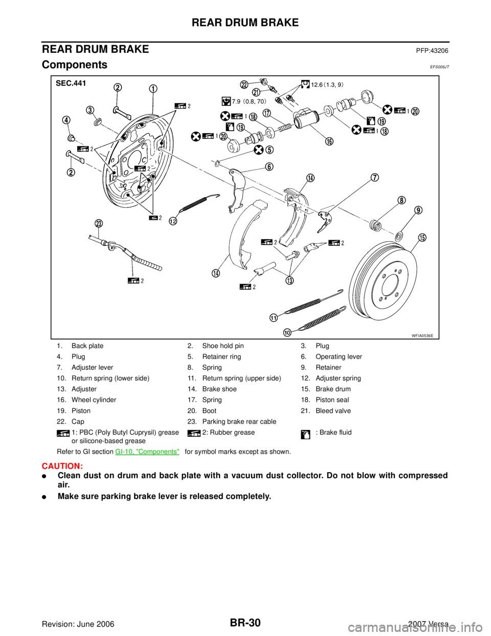
REAR DRUM BRAKEPFP:43206
ComponentsEFS006JT
CAUTION:
�Clean dust on drum and back plate with a vacuum dust collector. Do not blow with compressed
air.
�Make sure parking brake lever is released completely.
1. Back plate 2. Shoe hold pin 3. Plug
4. Plug 5. Retainer ring 6. Operating lever
7. Adjuster lever 8. Spring 9. Retainer
10. Return spring (lower side) 11. Return spring (upper side) 12. Adjuster spring
13. Adjuster 14. Brake shoe 15. Brake drum
16. Wheel cylinder 17. Spring 18. Piston seal
19. Piston 20. Boot 21. Bleed valve
22. Cap 23. Parking brake rear cable
1: PBC (Poly Butyl Cuprysil) grease
or silicone-based grease2: Rubber grease : Brake fluid
Refer to GI section GI-10, "
Components" for symbol marks except as shown.
WFIA0536E
Page 814 of 2896

REAR DRUM BRAKE
BR-31
C
D
E
G
H
I
J
K
L
MA
B
BR
Revision: June 20062007 Versa
Removal and Installation of Drum Brake AssemblyEFS006JU
REMOVAL
1. Remove tire from the vehicle.
2. With the parking brake lever released, remove the brake drum. If it is difficult to remove brake drum,
remove as follows:
a. Press up adjuster lever with a wire or equivalent from plug hole
(plug hole at the side of wheel cylinder) on the back plate as
shown in the figure. Turn frame of adjuster assembly with a flat
bladed screw driver in the direction that narrows frame to narrow
enlarged brake shoe.
3. While pushing and rotating the retainer, pull out shoe hold pin, and remove shoe assembly.
CAUTION:
Do not damage the wheel cylinder boot.
4. Remove the parking brake rear cable from the operating lever.
CAUTION:
Do not bend the parking brake cable.
5. Disassemble the shoe assembly (shoe, springs, adjuster, adjuster lever).
6. Remove retainer ring (A) with a tool to separate operating lever
(C) from brake shoe.
�Retainer ring (A)
�Contact point (B)
�Operating lever (C)
�Pin (D)
INSPECTION AFTER REMOVAL
Lining Thickness Inspection
Check lining thickness.
SFIA3080E
SFIA3075E
Standard thickness (A) : 4.0 mm (0.157 in)
Repair limit thickness (A) : 1.5 mm (0.059 in)
SBR0 21 A
Page 816 of 2896
 to brake shoes slid-
ing surfaces (the shaded areas) and other parts on the back")
REAR DRUM BRAKE
BR-33
C
D
E
G
H
I
J
K
L
MA
B
BR
Revision: June 20062007 Versa
2. Apply NISSAN brake grease (KRF0000005) to brake shoes slid-
ing surfaces (the shaded areas) and other parts on the back
plate as indicated by arrows.
3. Apply NISSAN brake grease (KRF00 00005) to screw and con-
firm the difference between right and left wheel for assembling
when disassembled.
4. Assemble the shoe, adjuster, adjuster lever and springs to the shoe assembly.
5. Connect the parking brake rear cable to the operating lever.
6. Install the shoe assembly. After assembly, be sure that each part is installed properly.
CAUTION:
Do not damage the wheel cylinder piston boot.
7. Install the brake drum.
8. Depress brake pedal for several times (approximately 2, 3 times).
9. Adjust clearance of brake shoe. Refer to PB-4, "
ADJUSTMENT" .
10. Install tires to the vehicle.
Removal and Installation of Wheel CylinderEFS006JV
REMOVAL
1. Drain brake fluid. Refer to BR-9, "Drain and Refill" .
2. Remove the rear brake shoe assembly. Refer to BR-31, "
Removal and Installation of Drum Brake Assem-
bly" .
3. Remove the brake tube from the wheel cylinder.
4. Remove bolts on the wheel cylinder, and then remove wheel cylinder from the back plate.
INSTALLATION
�Installation is the reverse order of removal. Tighten bolts to the specified torque. Refer to BR-30, "Compo-
nents" .
�Refill with new brake fluid and bleed air. Refer to BR-10, "Bleeding Brake System" .
WFIA0529E
Right rear
wheelThread cutting
direction: Right-hand screw
Left rear
wheelThread cutting
direction: Left-hand screw
SFIA3076E