Page 646 of 2896

INTELLIGENT KEY SYSTEM
BL-157
C
D
E
F
G
H
J
K
L
MA
B
BL
Revision: June 20062007 Versa
2. CHECK OTHER WARNING CHIME OPERATION
Check other warning chime operation using combination meter.
OK or NG
OK >> INSPECTION END
NG >> GO TO DI-47, "
WARNING CHIME" .
Hazard Function CheckEIS0092S
1. CHECK HAZARD WARNING LAMP
Do hazard warning lamps flash with hazard switch?
YES or NO
YES >> Hazard warning lamp circuit is OK.
NO >> Check hazard circuit. Refer to LT- 5 1 , "
TURN SIGNAL AND HAZARD WARNING LAMPS" .
Horn Function CheckEIS0092T
First perform the “SELF-DIAG RESULTS” of “BCM” with CONSULT-II, then perform the trouble diagno-
sis of malfunction system indicated in “SELF-DIAG RESULTS” of “BCM”. Refer to BCS-18, "
CAN Com-
munication Inspection Using CONSULT-II (Self-Diagnosis)".
1. CHECK HORN OPERATION
Check if horn sounds with horn switch.
Does horn operate?
Yes >> GO TO 2.
No >> Check horn circuit. Refer to WW-46, "
HORN" .
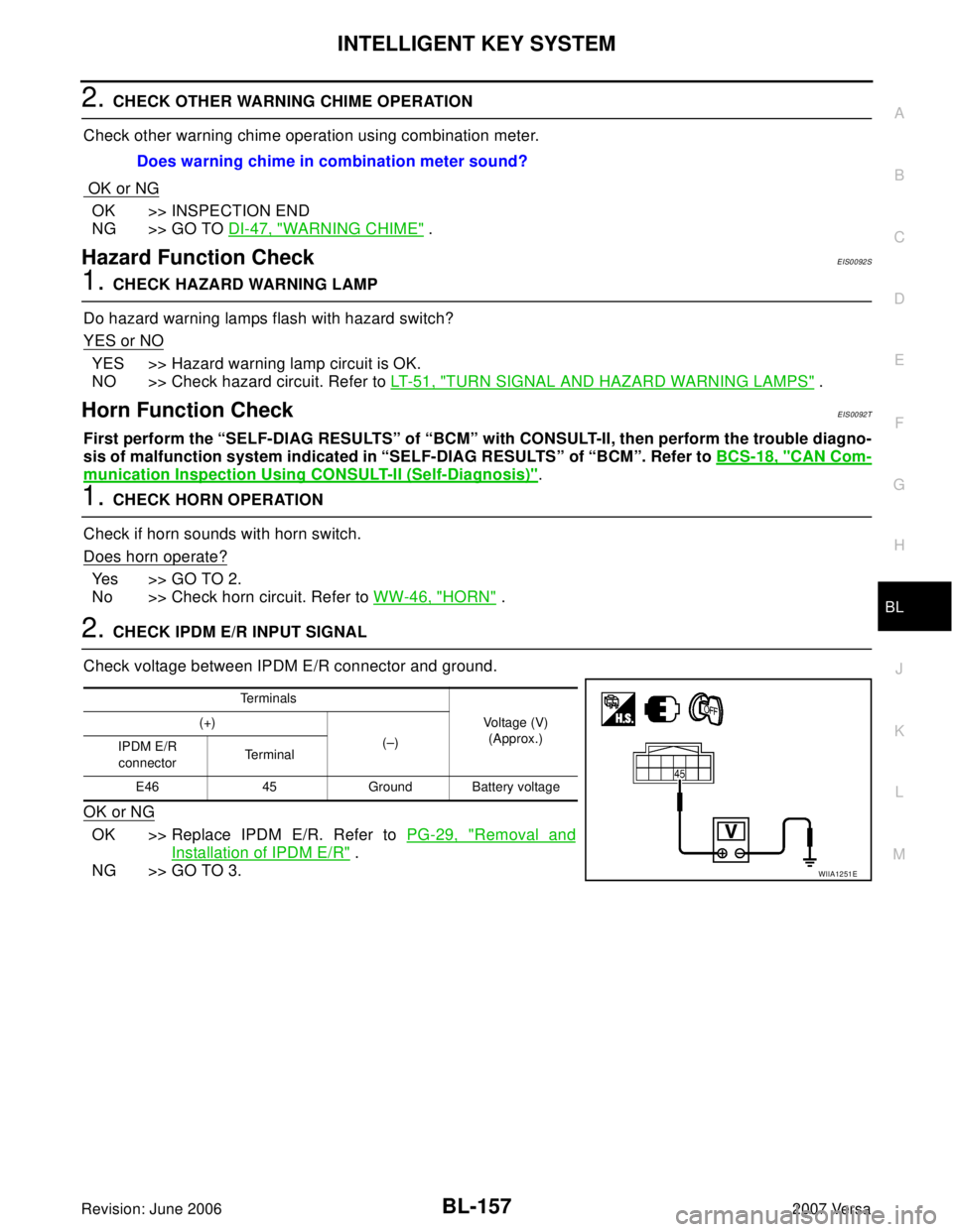
2. CHECK IPDM E/R INPUT SIGNAL
Check voltage between IPDM E/R connector and ground.
OK or NG
OK >> Replace IPDM E/R. Refer to PG-29, "Removal and
Installation of IPDM E/R" .
NG >> GO TO 3.Does warning chime in combination meter sound?
Te r m i n a l s
Voltage (V)
(Approx.) (+)
(–)
IPDM E/R
connectorTe r m i n a l
E46 45 Ground Battery voltage
WIIA1251E
Page 647 of 2896
BL-158
INTELLIGENT KEY SYSTEM
Revision: June 20062007 Versa
3. CHECK HORN RERAY CIRCUIT
1. Turn ignition switch OFF.
2. Disconnect IPDM E/R and horn relay connector.
3. Check continuity between IPDM E/R harness connector and
horn relay harness connector.
4. Check continuity between IPDM E/R harness connector and
ground.
OK or NG
OK >> Check condition of harness and connector.
NG >> Repair or replace harness.
Headlamp Function CheckEIS0092U
1. CHECK HEADLAMP OPERATION
Check if headlamps operate by lighting switch.
Do headlamps come on when turning lighting switch ON?
YES >> Headlamp circuit is OK.
NO >> Check headlamp system. Refer to LT- 5 , "
HEADLAMP (FOR USA)" or LT-27, "HEADLAMP (FOR
CANADA) - DAYTIME LIGHT SYSTEM -" .
AB
Continuity
IPDM E/R
connectorTe r m i n a lHorn relay
connectorTe r m i n a l
E46 45 H-1 1 Yes
A
GroundContinuity
IPDM E/R connector Terminal
E46 45 No
WIIA1252E
Page 648 of 2896

INTELLIGENT KEY SYSTEM
BL-159
C
D
E
F
G
H
J
K
L
MA
B
BL
Revision: June 20062007 Versa
Intelligent Key Battery ReplacementEIS0092W
DISASSEMBLY AND ASSEMBLY OF INTELLIGENT KEY
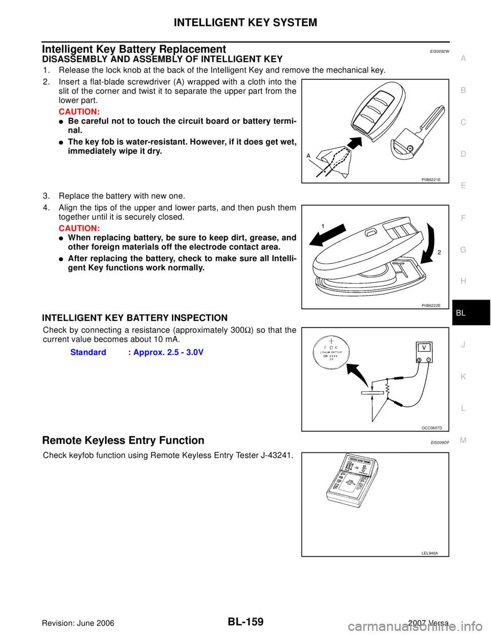
1. Release the lock knob at the back of the Intelligent Key and remove the mechanical key.
2. Insert a flat-blade screwdriver (A) wrapped with a cloth into the
slit of the corner and twist it to separate the upper part from the
lower part.
CAUTION:
�Be careful not to touch the circuit board or battery termi-
nal.
�The key fob is water-resistant. However, if it does get wet,
immediately wipe it dry.
3. Replace the battery with new one.
4. Align the tips of the upper and lower parts, and then push them
together until it is securely closed.
CAUTION:
�When replacing battery, be sure to keep dirt, grease, and
other foreign materials off the electrode contact area.
�After replacing the battery, check to make sure all Intelli-
gent Key functions work normally.
INTELLIGENT KEY BATTERY INSPECTION
Check by connecting a resistance (approximately 300Ω) so that the
current value becomes about 10 mA.
Remote Keyless Entry FunctionEIS0 09 DF
Check keyfob function using Remote Keyless Entry Tester J-43241.
PIIB6221E
PIIB6222E
Standard : Approx. 2.5 - 3.0V
OCC0607D
LEL946A
Page 649 of 2896
BL-160
INTELLIGENT KEY SYSTEM
Revision: June 20062007 Versa
Removal and Installation of Intelligent Key UnitEIS0092V
REMOVAL
1. Remove glove box assembly. Refer to IP-11, "Removal and Installation" .
2. Disconnect Intelligent Key unit connector, remove screw and
Intelligent Key unit.
INSTALLATION
Installation is in the reverse order of removal.
PIIB6534E
Page 658 of 2896

FRONT DOOR LOCK
BL-169
C
D
E
F
G
H
J
K
L
MA
B
BL
Revision: June 20062007 Versa
FRONT DOOR LOCKPFP:80502
Component Parts LocationEIS00932
Removal and InstallationEIS00933
REMOVAL
1. Remove front door finisher. Refer to EI-27, "Removal and Installation" .
2. Fully close front door window.
3. Remove the front door sealing screen.
NOTE:
If sealing screen is reused, cut butyl tape in a way that leaves it on the sealing screen.
4. Remove front door rear glass run channel. Refer to GW-43, "
Removal and Installation" .
5. Remove the cables from the holder.
6. Remove inside handle bolt, and slide the handle toward the rear
of the vehicle. disengage the handle from the door panel, and
remove the inside handle.
7. Disengage the handle from the door panel, and remove the inside handle.
1. Front door 2. Inside handle 3. Inside handle cable
4. Door lock assembly 5. Outside handle cable 6. TORX bolt (T30)
7. Key cylinder connecting rod 8. Grommet 9. TORX bolt (T30)
10. Rear gasket 11. Door key cylinder assembly
(Driver's side)
Outside handle escutcheon
(passenger's side)12. Outside handle
13. Front gasket 14. Lock knob cable 15. Holder
16. Outside handle bracket
PIIB6523E
PIIB6524E
Page 659 of 2896
BL-170
FRONT DOOR LOCK
Revision: June 20062007 Versa
8. Disconnect the inside handle cable and lock knob cable from the
inside handle.
CAUTION:
During removal and installation, work so as not to bend the
ends of the lock knob cable and inside handle cable.
9. Remove the door side grommet, and the door key cylinder
assembly (escutcheon) bolt.
10. Remove the key cylinder connecting rod (key cylinder side).
11. If equipped, disconnect the door antenna, the door request
switch connector and remove the harness clamp. (Vehicle with
intelligent key systems only).
12. Remove the door cylinder assembly while pulling the outside
handle forward.
13. Pull the outside door handle forward and then slide it toward the
rear of the vehicle to remove.
14. Remove the front and rear gaskets.
PIIB6525E
PIIB5808E
PIIB5809E
PIIB5810E
PIIB6526E
Page 664 of 2896
BACK DOOR LOCK
BL-175
C
D
E
F
G
H
J
K
L
MA
B
BL
Revision: June 20062007 Versa
BACK DOOR LOCKPFP:90504
Component Parts and Harness Connector LocationEIS009DK
LIIA2638E
1. BCM M18, M19, M20
(view with glove box removed)2. Intelligent Key unit M52
(if equipped)3. Back door lock assembly (actuator)
D405
4. Back door opener switch D408 5. Front door lock actuator (door
unlock sensor) LH D3, RH D114
Page 665 of 2896

BL-176
BACK DOOR LOCK
Revision: June 20062007 Versa
System DescriptionEIS0 09 DL
Power is supplied at all times
�through 40A fusible link (letter g, located in fuse and fusible link box)
�to BCM terminal 70
�through 10A fuse [No. 8, located in fuse block (J/B)]
�to BCM terminal 57
�through 10A fuse [No. 31, located in fuse block (J/B)]
�to Intelligent Key unit terminal 11 (if equipped).
Ground is supplied
�to BCM terminal 67 and
�to Intelligent Key unit terminal 12 (if equipped)
�through body grounds M57 and M61.
When back door opener switch is ON (pushed), ground is supplied
�to BCM terminal 30 (without Intelligent Key)
�through back door opener switch terminals 1 and 2
�through front door lock actuator LH (door unlock sensor) terminals 4 and 5 (without power windows) or
�through front door lock actuator RH (door unlock sensor) terminals 4 and 5 (with power windows)
�through body grounds M57 and M61
�to Intelligent Key unit terminal 24 (if equipped)
�through back door opener switch terminals 1 and 2
�through body grounds B117, B132 and D402.
Then power is supplied
�through BCM terminal 53
�to back door lock assembly (actuator) terminal 1.
Ground is supplied
�to back door lock assembly (actuator) terminal 2
�through body grounds B117, B132 and D402.
Then BCM operates back door lock assembly (actuator).