Page 630 of 2896
INTELLIGENT KEY SYSTEM
BL-141
C
D
E
F
G
H
J
K
L
MA
B
BL
Revision: June 20062007 Versa
Outside Key Antenna (Rear Bumper) CheckEIS0092M
1. CHECK REAR BUMPER ANTENNA FUNCTION
With CONSULT-II
1. Check the operation with (“ANTENNA”) in the ACTIVE TEST.
2. Touch “BD/TR ANT” on screen.
3. Carry the Intelligent Key into the antenna detection area.
Do the hazard lamps flash?
Yes >> Rear bumper antenna is OK.
No >> GO TO 2.
2. CHECK REAR BUMPER ANTENNA INPUT SIGNAL 1
1. Turn ignition switch OFF.
2. Check signal between Intelligent Key unit connector and ground with oscilloscope.
OK or NG
OK >> Rear bumper antenna is OK.
NG >> GO TO 3.
Test item Corresponding antenna
BK DOOR ANT Rear bumper antenna
PIIB6625E
Terminals
ConditionSignal
(Reference value.) (+)
(–) Intelligent
Key unit
connectorTe r m i n a l
M52 17 GroundBack door
request
switch is
pushed
PIIB6628E
SIIA1910J
Page 631 of 2896

BL-142
INTELLIGENT KEY SYSTEM
Revision: June 20062007 Versa
3. CHECK REAR BUMPER ANTENNA CIRCUIT
1. Disconnect Intelligent Key unit and rear bumper antenna connector.
2. Check continuity between Intelligent Key unit connector and rear bumper antenna connector.
3. Check continuity between Intelligent Key unit connector and
ground.
OK or NG
OK >> GO TO 4.
NG >> Repair or replace harness between Intelligent Key unit and rear bumper antenna.
4. CHECK REAR BUMPER ANTENNA INPUT SIGNAL 2
1. Replace rear bumper antenna (new antenna or other antenna).
2. Connect Intelligent Key unit and rear bumper antenna connector.
3. Check signal between Intelligent Key unit connector and ground with oscilloscope.
OK or NG
OK >> Replace rear bumper antenna.
NG >> Replace Intelligent Key unit. Refer to BL-160, "
Removal and Installation of Intelligent Key Unit" .
AB
Continuity
Intelligent Key
unit connectorTe r m i n a lRear bumper
antenna connectorTe r m i n a l
M5217
B21
Ye s
18 2
A
GroundContinuity
Intelligent Key unit
connectorTe r m i n a l
M5217
No
18
PIIB6629E
Te r m i n a l s
ConditionSignal
(Reference value.) (+)
(–) Intelligent
Key unit
connectorTe r m i n a l
M52 17 GroundBack door
request
switch is
pushed
PIIB6628E
SIIA1910J
Page 632 of 2896

INTELLIGENT KEY SYSTEM
BL-143
C
D
E
F
G
H
J
K
L
MA
B
BL
Revision: June 20062007 Versa
Inside Key Antenna CheckEIS0092N
1. CHECK INSIDE KEY ANTENNA INPUT SIGNAL 1
1. Turn ignition switch OFF.
2. Check signal between Intelligent Key unit connector and ground with oscilloscope.
OK or NG
OK >> Check the condition of harness and connector.
NG >> GO TO 2.
2. CHECK INSIDE KEY ANTENNA CIRCUIT
1. Disconnect Intelligent Key unit and inside key antenna connector.
2. Check continuity between Intelligent Key unit connector and inside key antenna connector.
3. Check continuity between Intelligent Key unit connector and ground.
OK or NG
OK >> GO TO 3.
NG >> Repair or replace harness between Intelligent Key unit and inside key antenna.
Terminals
ConditionSignal
(Reference value.) (+)
(–)
Intelligent Key
unit connectorTe r -
minal
M52Instrument
panel area13
GroundAny door
is open →
close Front con-
sole area15
Rear floor
area33
WIIA1200E
PIIB5502J
AB
Continuity
Intelligent Key
unit connectorTe r m i n a lInside key antenna
connectorTe r m i n a l
M5213
M10Instrument
panel2
Ye s 14 1
15
B3Front con-
sole1
16 2
33
B12 Rear floor1
34 2
A
GroundContinuity
Intelligent Key unit
connectorTe r m i n a l
M52Instrument panel13
No 14
Front console15
16
Rear floor33
34
WIIA1254E
Page 633 of 2896

BL-144
INTELLIGENT KEY SYSTEM
Revision: June 20062007 Versa
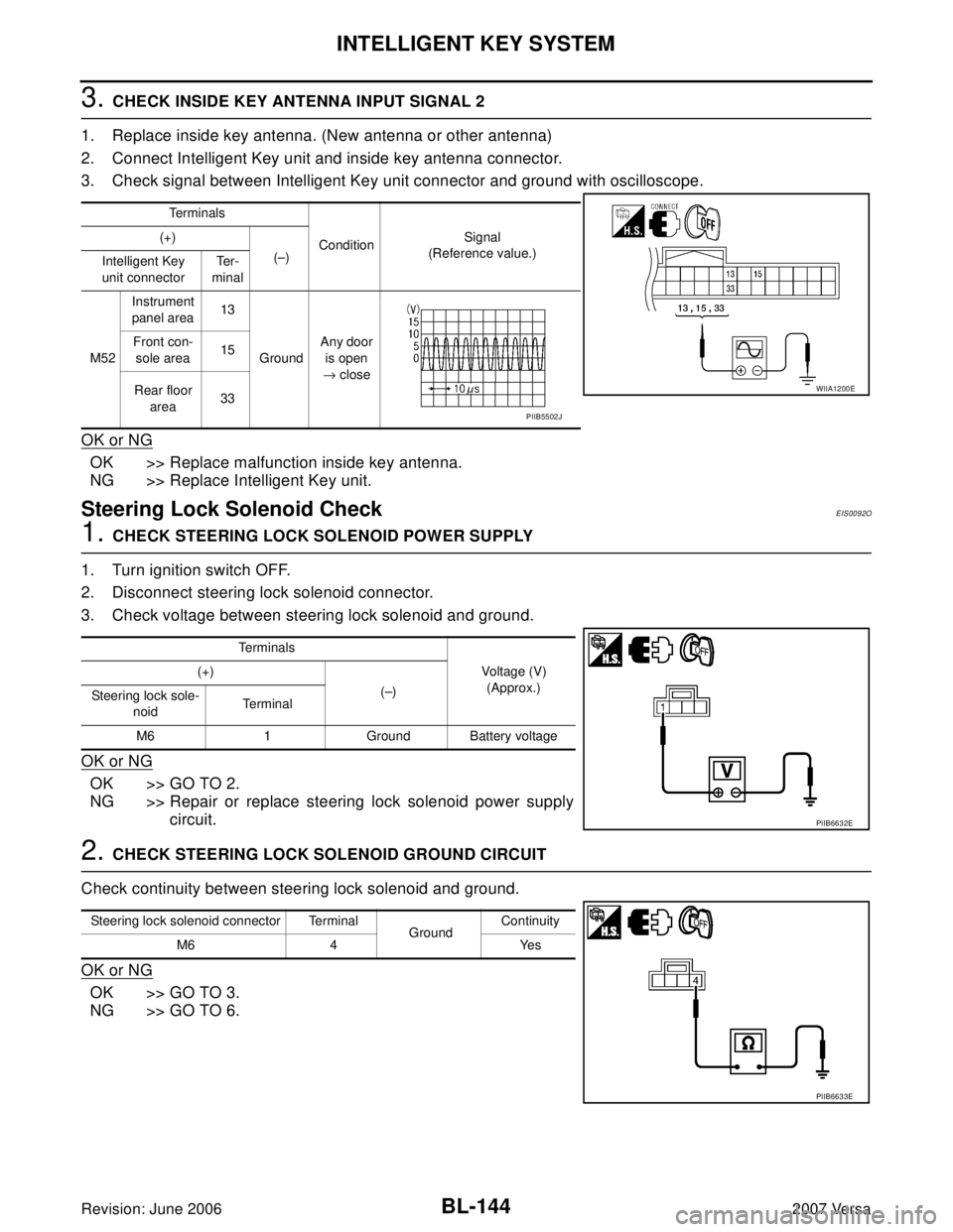
3. CHECK INSIDE KEY ANTENNA INPUT SIGNAL 2
1. Replace inside key antenna. (New antenna or other antenna)
2. Connect Intelligent Key unit and inside key antenna connector.
3. Check signal between Intelligent Key unit connector and ground with oscilloscope.
OK or NG
OK >> Replace malfunction inside key antenna.
NG >> Replace Intelligent Key unit.
Steering Lock Solenoid CheckEIS0092O
1. CHECK STEERING LOCK SOLENOID POWER SUPPLY
1. Turn ignition switch OFF.
2. Disconnect steering lock solenoid connector.
3. Check voltage between steering lock solenoid and ground.
OK or NG
OK >> GO TO 2.
NG >> Repair or replace steering lock solenoid power supply
circuit.
2. CHECK STEERING LOCK SOLENOID GROUND CIRCUIT
Check continuity between steering lock solenoid and ground.
OK or NG
OK >> GO TO 3.
NG >> GO TO 6.
Te r m i n a l s
ConditionSignal
(Reference value.) (+)
(–)
Intelligent Key
unit connectorTe r -
minal
M52Instrument
panel area13
GroundAny door
is open
→ close Front con-
sole area15
Rear floor
area33
WIIA1200E
PIIB5502J
Te r m i n a l s
Voltage (V)
(Approx.) (+)
(–)
Steering lock sole-
noidTerminal
M6 1 Ground Battery voltage
PIIB6632E
Steering lock solenoid connector Terminal
GroundContinuity
M6 4 Yes
PIIB6633E
Page 634 of 2896
INTELLIGENT KEY SYSTEM
BL-145
C
D
E
F
G
H
J
K
L
MA
B
BL
Revision: June 20062007 Versa
3. CHECK INTELLIGENT KEY UNIT OUTPUT SIGNAL
1. Connect steering lock solenoid connector.
2. Check voltage between Intelligent Key unit and ground.
OK or NG
OK >> GO TO 4.
NG >> Replace Intelligent Key unit. Refer to BL-160, "
Removal
and Installation of Intelligent Key Unit" .
4. CHECK STEERING LOCK COMMUNICATION SIGNAL
Check signal between Intelligent Key unit and ground with oscilloscope.
OK or NG
OK >> GO TO 5.
NG >> Replace Intelligent Key unit. Refer to BL-160, "
Removal and Installation of Intelligent Key Unit" .
Te r m i n a l s
Voltage (V)
(Approx.) (+)
(–)
Intelligent Key unit
connectorTe r m i n a l
M52 1 Ground 5
PIIB6634E
Te r m i n a l s
Condition of
key switchVoltage (V)
(Approx.) (+)
(–) Intelligent
Key unit
connectorTe r m i n a l
M52 32 GroundIgnition
switch is
pressed,
when Intelli-
gent Key is
into the vehi-
cle.
Other than
above5
PIIB6635E
SIIA1911J
Page 635 of 2896

BL-146
INTELLIGENT KEY SYSTEM
Revision: June 20062007 Versa
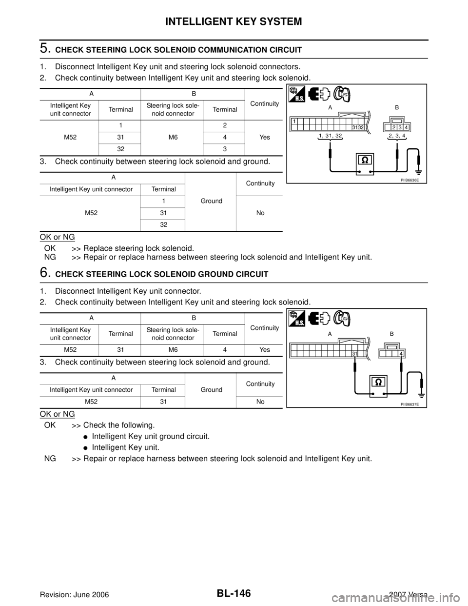
5. CHECK STEERING LOCK SOLENOID COMMUNICATION CIRCUIT
1. Disconnect Intelligent Key unit and steering lock solenoid connectors.
2. Check continuity between Intelligent Key unit and steering lock solenoid.
3. Check continuity between steering lock solenoid and ground.
OK or NG
OK >> Replace steering lock solenoid.
NG >> Repair or replace harness between steering lock solenoid and Intelligent Key unit.
6. CHECK STEERING LOCK SOLENOID GROUND CIRCUIT
1. Disconnect Intelligent Key unit connector.
2. Check continuity between Intelligent Key unit and steering lock solenoid.
3. Check continuity between steering lock solenoid and ground.
OK or NG
OK >> Check the following.
�Intelligent Key unit ground circuit.
�Intelligent Key unit.
NG >> Repair or replace harness between steering lock solenoid and Intelligent Key unit.
AB
Continuity
Intelligent Key
unit connectorTe r m i n a lSteering lock sole-
noid connectorTe r m i n a l
M521
M62
Ye s 31 4
32 3
A
GroundContinuity
Intelligent Key unit connector Terminal
M521
No 31
32
PIIB6636E
AB
Continuity
Intelligent Key
unit connectorTe r m i n a lSteering lock sole-
noid connectorTe r m i n a l
M52 31 M6 4 Yes
A
GroundContinuity
Intelligent Key unit connector Terminal
M52 31 No
PIIB6637E
Page 636 of 2896

INTELLIGENT KEY SYSTEM
BL-147
C
D
E
F
G
H
J
K
L
MA
B
BL
Revision: June 20062007 Versa
Key Interlock Solenoid (With M/T) CheckEIS009D7
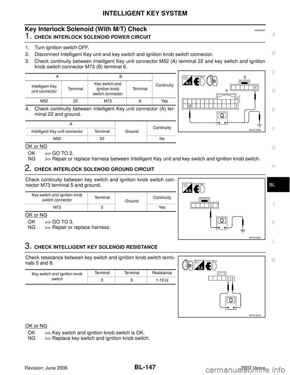
1. CHECK INTERLOCK SOLENOID POWER CIRCUIT
1. Turn ignition switch OFF.
2. Disconnect Intelligent Key unit and key switch and ignition knob switch connector.
3. Check continuity between Intelligent Key unit connector M52 (A) terminal 22 and key switch and ignition
knob switch connector M73 (B) terminal 6.
4. Check continuity between Intelligent Key unit connector (A) ter-
minal 22 and ground.
OK or NG
OK >> GO TO 2.
NG >> Repair or replace harness between Intelligent Key unit and key switch and ignition knob switch.
2. CHECK INTERLOCK SOLENOID GROUND CIRCUIT
Check continuity between key switch and ignition knob switch con-
nector M73 terminal 5 and ground.
OK or NG
OK >> GO TO 3.
NG >> Repair or replace harness.
3. CHECK INTELLIGENT KEY SOLENOID RESISTANCE
Check resistance between key switch and ignition knob switch termi-
nals 5 and 6.
OK or NG
OK >> Key switch and ignition knob switch is OK.
NG >> Replace key switch and ignition knob switch.
AB
Continuity
Intelligent Key
unit connectorTe r m i n a lKey switch and
ignition knob
switch connectorTe r m i n a l
M52 22 M73 6 Yes
A
GroundContinuity
Intelligent Key unit connector Terminal
M52 22 No
WIIA1268E
Key switch and ignition knob
switch connectorTe r m i n a l
GroundContinuity
M73 5 Yes
WIIA1266E
Key switch and ignition knob
switchTerminal Terminal Resistance
5 6 1-10 Ω
WIIA1301E
Page 637 of 2896

BL-148
INTELLIGENT KEY SYSTEM
Revision: June 20062007 Versa
Ignition Switch Position CheckEIS0092P
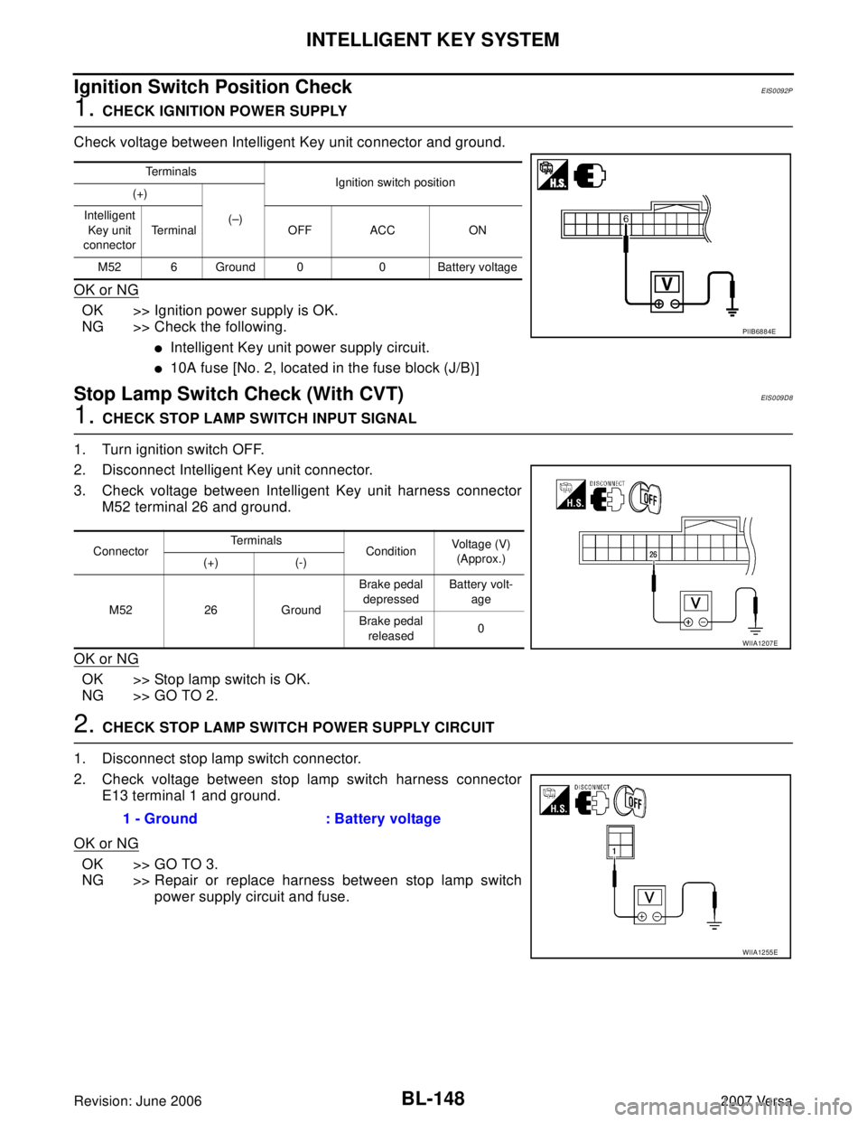
1. CHECK IGNITION POWER SUPPLY
Check voltage between Intelligent Key unit connector and ground.
OK or NG
OK >> Ignition power supply is OK.
NG >> Check the following.
�Intelligent Key unit power supply circuit.
�10A fuse [No. 2, located in the fuse block (J/B)]
Stop Lamp Switch Check (With CVT)EIS0 09 D8
1. CHECK STOP LAMP SWITCH INPUT SIGNAL
1. Turn ignition switch OFF.
2. Disconnect Intelligent Key unit connector.
3. Check voltage between Intelligent Key unit harness connector
M52 terminal 26 and ground.
OK or NG
OK >> Stop lamp switch is OK.
NG >> GO TO 2.
2. CHECK STOP LAMP SWITCH POWER SUPPLY CIRCUIT
1. Disconnect stop lamp switch connector.
2. Check voltage between stop lamp switch harness connector
E13 terminal 1 and ground.
OK or NG
OK >> GO TO 3.
NG >> Repair or replace harness between stop lamp switch
power supply circuit and fuse.
Te r m i n a l s
Ignition switch position
(+)
(–) Intelligent
Key unit
connectorTe r m i n a l O F F A C C O N
M52 6 Ground 0 0 Battery voltage
PIIB6884E
ConnectorTe r m i n a l s
ConditionVoltage (V)
(Approx.)
(+) (-)
M52 26 GroundBrake pedal
depressedBattery volt-
age
Brake pedal
released0
WIIA1207E
1 - Ground : Battery voltage
WIIA1255E