Page 983 of 1226
![NISSAN PATROL 2006 Service Manual Chassis and Body Services
Annual driving distance below 30,000 km (18,000 miles)
Abbreviations: R = Replace, I = Inspect, and correct or replace as necessary, L = Lubricate,T=Tighten.
[ ]: At the spec NISSAN PATROL 2006 Service Manual Chassis and Body Services
Annual driving distance below 30,000 km (18,000 miles)
Abbreviations: R = Replace, I = Inspect, and correct or replace as necessary, L = Lubricate,T=Tighten.
[ ]: At the spec](/manual-img/5/57368/w960_57368-982.png)
Chassis and Body Services
Annual driving distance below 30,000 km (18,000 miles)
Abbreviations: R = Replace, I = Inspect, and correct or replace as necessary, L = Lubricate,T=Tighten.
[ ]: At the speci®ed mileage only
MAINTENANCE OPERATIONMAINTENANCE INTERVAL
Reference
page Perform either at number of kilometers (miles) or months,
whichever comes ®rst.km x 1,000 10 20 30 40 50 60 70 80 90
(Miles x 1,000) (6) (12) (18) (24) (30) (36) (42) (48) (54)
Months 6 12 18 24 30 36 42 48 54
CHASSIS AND BODY Underhood and under vehicle
Brake & clutch ¯uid (For level & leaks).I I I I MA-23, 20
Brake ¯uid.R R MA-24
Brake booster vacuum hoses, connections & check valve I I MA-24
Power steering ¯uid & lines (For level & leaks) I I I I MA-26
Brake & clutch systemsI I I I MA-24, 20
Manual transmission oil (For leaks) I I I I MA-20
Manual transmission oil[R] MA-20
Transfer ¯uidI I R I MA-21
Limited slip differential (LSD) gear oil (For level & leaks).*1 I I R I MA-22
Steering gear & linkage, axle & suspension parts, propeller shaft & exhaust system.I I I I MA-26, 20 *2
Greasing points of propeller shaftLLLLMA-21
Drive shafts & steering damper.IIII *3
Body mounting bolts & nutsTTTT *4
Outside and Inside
Wheel alignment (If necessary, rotate & balance wheels) I I I I MA-25, *5
Brake pads, discs & other brake components.I I I I MA-24
Front wheel bearing grease I R I R MA-22
Axle joint in knuckle ¯angeL L MA-23
Free running hub greaseI I I I MA-23
Headlamp aimingIIII *6
Foot brake, parking brake & clutch (For free play, stroke & operation) I I I I *7
Ventilation air ®lterRRR*8
Body corrosionAnnually MA-28
Air bag systemSee NOTE (1) *9
NOTE: (1) Inspect after 10 years, then every 2 years.
(2) Maintenance items with ``.'' should be performed more frequently according to ``Maintenance Under Severe Driv-
ing Conditions''.
*1: Including differential gear with differential lock
*2: ``Front Axle and Front Suspension Parts'' in FA section, ``Rear Axle and Rear Suspension Parts'' in RA section
*3: ``FRONT AXLE Ð Drive Shaft'' in FA section
*4: ``CAB BODY'' in BT section
*5: ``Front Wheel Alignment'' in FA section
*6: ``Aiming Adjustment'' in EL section
*7: ``Brake Pedal and Bracket'' in BR section, ``Adjusting Clutch Pedal'' in CL section
*8: ``Ventilation air ®lter'' in HA section
*9: ``Maintenance Items'' in RS section
PERIODIC MAINTENANCE
MA-6
Page 984 of 1226

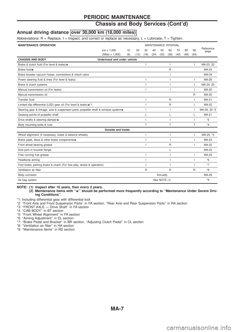
Annual driving distance over 30,000 km (18,000 miles)
Abbreviations: R = Replace. I = Inspect, and correct or replace as necessary, L = Lubricate,T=Tighten.
MAINTENANCE OPERATIONMAINTENANCE INTERVAL
Reference
page km x 1,000 10 20 30 40 50 60 70 80 90
(Miles x 1,000) (6) (12) (18) (24) (30) (36) (42) (48) (54)
CHASSIS AND BODY Underhood and under vehicle
Brake & clutch ¯uid (For level & leaks).I I I MA-23, 20
Brake ¯uid.R MA-24
Brake booster vacuum hoses, connections & check valve I MA-24
Power steering ¯uid & lines (For level & leaks) I I I MA-26
Brake & clutch systemsI I I MA-24, 20
Manual transmission oil (For leaks) I I I MA-20
Manual transmission oilR MA-20
Transfer ¯uidI R I MA-21
Limited slip differential (LSD) gear oil (For level & leaks).*1 I R I MA-22
Steering gear & linkage, axle & suspension parts, propeller shaft & exhaust system.I I I MA-26, 20 *2
Geasing points of propeller shaft L L L MA-21
Drive shafts & steering damper.III*3
Body mounting bolts & nutsTTT*4
Outside and Inside
Wheel alignment (If necessary, rotate & balance wheels) I I I MA-25, *5
Brake pads, discs & other brake components.I I I MA-24
Front wheel bearing greaseI R I MA-22
Axle joint in knuckle ¯angeL MA-23
Free running hub greaseI I I MA-23
Headlamp aimingIII*6
Foot brake, parking brake & clutch (For free play, stroke & operation) I I I *7
Ventilation air ®lterRRR*8
Body corrosionAnnually MA-28
Air bag systemSee NOTE (1) *9
NOTE: (1) Inspect after 10 years, then every 2 years.
(2) Maintenance items with ``.'' should be performed more frequently according to ``Maintenance Under Severe Driv-
ing Conditions''.
*1: Including differential gear with differential lock
*2: ``Front Axle and Front Suspension Parts'' in FA section, ``Rear Axle and Rear Suspension Parts'' in RA section
*3: ``FRONT AXLE Ð Drive Shaft'' in FA section
*4: ``CAB BODY'' in BT section
*5: ``Front Wheel Alignment'' in FA section
*6: ``Aiming Adjustment'' in EL section
*7: ``Brake Pedal and Bracket'' in BR section, ``Adjusting Clutch Pedal'' in CL section
*8: ``Ventilation air ®lter'' in HA section
*9: ``Maintenance Items'' in RS section
PERIODIC MAINTENANCE
Chassis and Body Services (Cont'd)
MA-7
Page 996 of 1226
6. Install all injection nozzles with Tool and securely connect fuel
spill tube and delivery tubes.
7. Bleed air from fuel system and check for fuel leakage with
engine running.
Injection nozzle to cylinder head:
:59-69Nzm (6.0 - 7.0 kg-m, 43 - 51 ft-lb)
Spill tube nut:
:39-49Nzm (4.0 - 5.0 kg-m, 29 - 36 ft-lb)
Injection tube:
:20-25Nzm (2.2 - 2.5 kg-m, 16 - 18 ft-lb)
Checking Idle Speed
Inspection should be carried out with gears in ``Neutral'' and
with air conditioner and other electrical loads off.
1. Warm up engine until engine coolant temperature indicator
points to the middle of gauge.
2. Attach a diesel tachotester's pick-up to No. 1 fuel injection tube.
3. Race engine two or three times and check idle speed.
Idle speed:
Unit: rpm
MT 750+50
þ0
Timing Belt Replacement
Refer to EM section.
ENGINE MAINTENANCE
Checking Injection Nozzle (Cont'd)
MA-19
Page 1038 of 1226
13. Tighten control housing bolts.
Bolt head size:
A bolts 12 mm (0.47 in)
B bolts 13 mm (0.51 in)
SMT446BA
ASSEMBLY
Case Components (Cont'd)
MT-31
Page 1069 of 1226
To avoid confusion while calculating bearing shims, it is absolutely
necessary to stay with the metric system. If you measure anything
in inches,the results must be converted to the metric system.
Drive Pinion Height
1. First prepare Tools for pinion height adjustment.
:
V1Heightgauge(ST31251000)*
V2Dummyshaft(ST31181001)*
V3SpacerKV38108700 [thickness: 2.00mm (0.0787 in)]*
V4Feelergauge (commercial servcie tool)
2. To simplify the job, make a chart, like the one below, to orga- nize your calculations.
LETTERS HUNDREDTHS OF
A MILLIMETER
H: Head number
D ¢: Figure marked on dummy shaft
S: Figure marked on height gauge
N:Measuringclearance
* Set tools are available: ST3125S000 (tools 1 and 2) ST3125S001 (tools 1, 2 and 3)
3. Write the following numbers down the chart.H: Head number
D¢: Figure marked on dummy shaft.
SPD758
SPD542
SPD759
ADJUSTMENT
PD-27
Page 1073 of 1226
Differential Case Ð 4-pinion type Ð
1. Measure clearance between side gear thrust washer and dif-
ferential case.
Clearance between side gear thrust washer
and differential case (A Ð B):
0.15 - 0.20 mm (0.0059 - 0.0079 in)
The clearance can be adjusted with side gear thrust washer.
Refer to SDS.
2. Apply oil to gear tooth surfaces and thrust surfaces and check
that they turn properly.
3. Install differential case LH and RH.
4. Place differential case on ring gear.
5. Apply locking sealer to ring gear bolts, and install them.
Tighten bolts in a criss-cross fashion, lightly tapping bolt head
with a hammer.
6. Press-®t side bearing inner races on differential case with Tool.
Tool number:
j
AST33190000
j
BST02371000
SPD656
SPD643
SPD746
PD353
ASSEMBLY
PD-31
Page 1074 of 1226
Differential Case Ð 2-pinion type Ð
1. Install side gears, pinion mate gears and thrust washers into
differential case.
2. Fit pinion mate shaft to differential case so that it meets lock pin
holes.
3. Adjust backlash between side gear and pinion mate gear by
selecting side gear thrust washer. Refer to SDS.
Backlash between side gear and pinion mate gear
(Clearance between side gear thrust washer and dif-
ferential case):
0.15 - 0.20 mm (0.0059 - 0.0079 in)
4. Install pinion mate shaft lock pin with a punch.
Make sure lock pin is ¯ush with case.
5. Apply gear oil to gear tooth surfaces and thrust surfaces and
make sure they turn properly.
6. Install differential case assembly on ring gear.
Tighten bolts in a criss-cross pattern, lightly tapping bolt head
with a hammer.
7. Press-®t side bearing inner cones on differential case with Tool.
Tool number:
j
AST33190000
j
BST02371000
SPD552
SPD258
SPD030
SPD322
PD353
ASSEMBLY
PD-32
Page 1138 of 1226

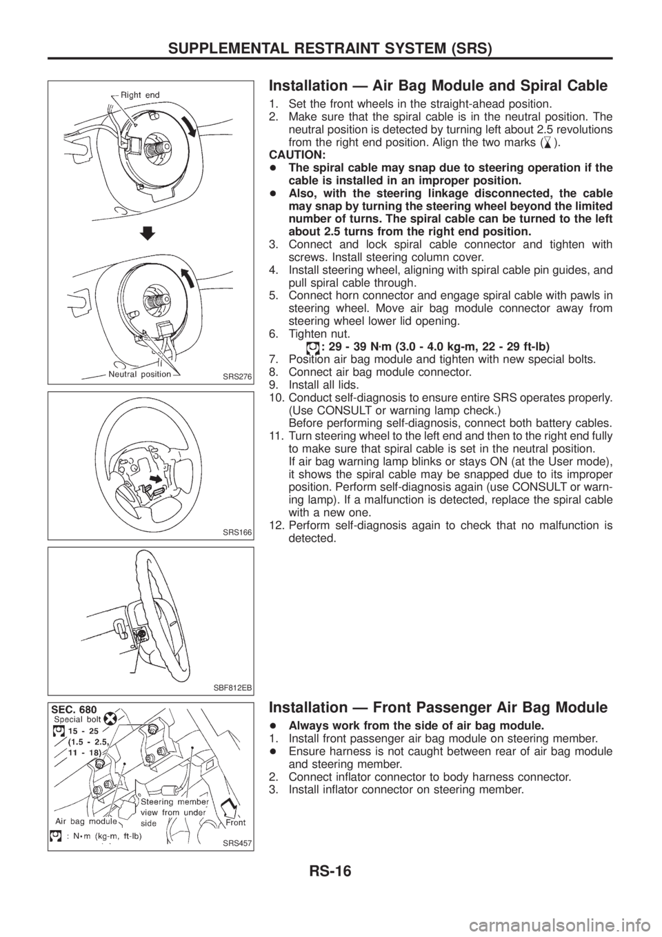
Installation Ð Air Bag Module and Spiral Cable
1. Set the front wheels in the straight-ahead position.
2. Make sure that the spiral cable is in the neutral position. The
neutral position is detected by turning left about 2.5 revolutions
from the right end position. Align the two marks (
,
m).
CAUTION:
+The spiral cable may snap due to steering operation if the
cable is installed in an improper position.
+Also, with the steering linkage disconnected, the cable
may snap by turning the steering wheel beyond the limited
number of turns. The spiral cable can be turned to the left
about 2.5 turns from the right end position.
3. Connect and lock spiral cable connector and tighten with
screws. Install steering column cover.
4. Install steering wheel, aligning with spiral cable pin guides, and
pull spiral cable through.
5. Connect horn connector and engage spiral cable with pawls in
steering wheel. Move air bag module connector away from
steering wheel lower lid opening.
6. Tighten nut.
:29-39Nzm (3.0 - 4.0 kg-m, 22 - 29 ft-lb)
7. Position air bag module and tighten with new special bolts.
8. Connect air bag module connector.
9. Install all lids.
10. Conduct self-diagnosis to ensure entire SRS operates properly.
(Use CONSULT or warning lamp check.)
Before performing self-diagnosis, connect both battery cables.
11. Turn steering wheel to the left end and then to the right end fully
to make sure that spiral cable is set in the neutral position.
If air bag warning lamp blinks or stays ON (at the User mode),
it shows the spiral cable may be snapped due to its improper
position. Perform self-diagnosis again (use CONSULT or warn-
ing lamp). If a malfunction is detected, replace the spiral cable
with a new one.
12. Perform self-diagnosis again to check that no malfunction is
detected.
Installation Ð Front Passenger Air Bag Module
+Always work from the side of air bag module.
1. Install front passenger air bag module on steering member.
+Ensure harness is not caught between rear of air bag module
and steering member.
2. Connect in¯ator connector to body harness connector.
3. Install in¯ator connector on steering member.
SRS276
SRS166
SBF812EB
SRS457
SUPPLEMENTAL RESTRAINT SYSTEM (SRS)
RS-16