Page 680 of 1226

6. Fit compression gauge adapter to cylinder head.
7. Crank engine and read gauge indication.
Crank speed: 200 rpm
Compression pressure:
Standard
3,040 kPa (30.4 bar, 31 kg/cm
2, 441 psi)
Limit
2,452 kPa (24.5 bar, 25 kg/cm
2, 356 psi)
Differential limit between cylinders
490 kPa (4.9 bar, 5 kg/cm
2, 71 psi)
8. If the pressure appears low, pour about 3 m!(0.11 Imp ¯ oz)
of engine oil through nozzle holes and repeat test.
For indications of test, refer to the following table.
Gauge indication during tests Trouble diagnosis
SEM857
+Piston rings are worn or
damaged.
SEM858
+If two adjacent cylinders
are low, gasket is dam-
aged.
+Valve is sticking.
+Valve seat or valve con-
tact surface is incorrected.
9. Replace nozzle gaskets and install injection nozzles.
New nozzle gasket installation direction is as shown.
Nozzle to cylinder head:
:59-69Nzm
(6.0 - 7.0 kg-m, 43 - 51 ft-lb)
SEM706B
SEM708B
COMPRESSION PRESSURE
Measurement of Compression Pressure
(Cont'd)
EM-12
First readingSecond
reading
Increased
reading
Same reading
maintained
Page 684 of 1226
CAUTION:
+Do not bend or twist timing belt.
+After removing timing belt, do not turn crankshaft and
camshaft separately because valves will strike piston
heads.
+Make sure that timing belt, camshaft sprocket, crankshaft
sprocket, idler pulley, injection pump pulley and belt ten-
sioner are clean and free from oil and water.
+Align white lines on timing belt with punch mark on cam-
shaft sprocket, crankshaft sprocket and injection pump
pulley.
+Installation should be carried out when engine is cold.
Removal
1. Remove radiator shroud.
2. Remove the following belts.
+Power steering drive belt
+A/C compressor drive belt
+Alternator drive belt
3. Remove cooling fan coupling and water pump pulley.
SMA767BA
TIMING BELT
EM-16
Page 685 of 1226
4. Set No. 1 cylinder at bottom dead center (BDC) on its expan-
sion stroke, as shown.
5. Remove the starter motor and wipe off the liquid gasket remain-
ing on the connecting part.
6. Install the ring gear stopper using the bolt holes for ®xing the
starter motor.
7. Remove crankshaft pulley using puller.
Be sure to securely attach puller jaws. Attach jaws only to the
rear side of pulley.
8. Remove front cover.
9. Remove tensioner spring and loosen belt tensioner lock nut.
10. Remove timing belt.
After removing timing belt, do not turn crankshaft and cam-
shaft separately, because valves will strike piston heads.
SMA768B
SMA769B
SMA770B
TIMING BELT
Removal (Cont'd)
EM-17
Page 689 of 1226

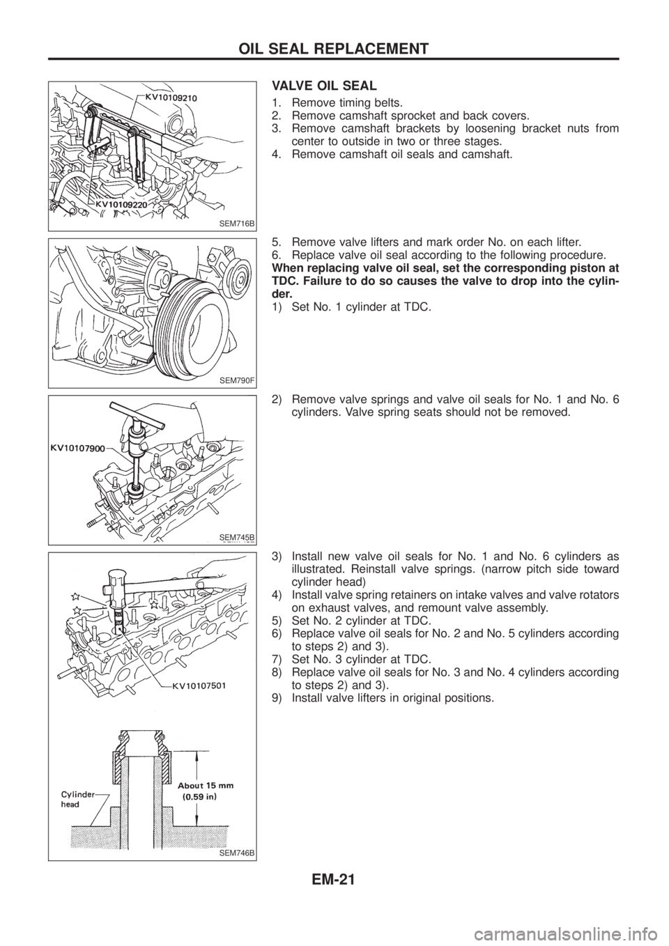
VALVE OIL SEAL
1. Remove timing belts.
2. Remove camshaft sprocket and back covers.
3. Remove camshaft brackets by loosening bracket nuts from
center to outside in two or three stages.
4. Remove camshaft oil seals and camshaft.
5. Remove valve lifters and mark order No. on each lifter.
6. Replace valve oil seal according to the following procedure.
When replacing valve oil seal, set the corresponding piston at
TDC. Failure to do so causes the valve to drop into the cylin-
der.
1) Set No. 1 cylinder at TDC.
2) Remove valve springs and valve oil seals for No. 1 and No. 6
cylinders. Valve spring seats should not be removed.
3) Install new valve oil seals for No. 1 and No. 6 cylinders as
illustrated. Reinstall valve springs. (narrow pitch side toward
cylinder head)
4) Install valve spring retainers on intake valves and valve rotators
on exhaust valves, and remount valve assembly.
5) Set No. 2 cylinder at TDC.
6) Replace valve oil seals for No. 2 and No. 5 cylinders according
to steps 2) and 3).
7) Set No. 3 cylinder at TDC.
8) Replace valve oil seals for No. 3 and No. 4 cylinders according
to steps 2) and 3).
9) Install valve lifters in original positions.
SEM716B
SEM790F
SEM745B
SEM746B
OIL SEAL REPLACEMENT
EM-21
Page 692 of 1226
Removal and Installation
1. Drain engine coolant.
2. Remove the following:
+Air duct and hoses
+Air intake pipe
+EGR pipe
+Heat shield plates
+Intake manifold
+Front (exhaust) tube
+Oil tube and water tube
3. Remove exhaust manifold with turbocharger from cylinder
head.
4. When installing turbocharger to exhaust manifold, securely
tighten nuts and lock the nuts.
+Turbocharger should not be disassembled.
SEM784F
TURBOCHARGER
EM-24
Page 697 of 1226
SEM785F
CYLINDER HEAD
EM-29
Page 698 of 1226
CAUTION:
+When installing sliding parts such as camshaft and oil
seal, be sure to apply new engine oil on their sliding sur-
faces.
+When tightening cylinder head bolts, apply new engine oil
to thread portions and seat surfaces of bolts.
Removal
1. Remove charge air cooler assembly.
2. Set No. 1 cylinder at BDC on its expansion stroke.
3. Drain engine coolant from drain plugs on cylinder block and
radiator.
4. Remove air cleaner and/or air duct.
5. Remove timing belt.
6. Remove rocker cover securing bolts/nuts in numerical order
shown in ®gure.
To install rocker cover, tighten bolts/nuts in reverse order of
removal. Tighten in two or three stages.
7. Remove camshaft sprocket, injection pump drive sprocket and
back cover.
8. Disconnect exhaust manifold from exhaust tube.
9. Remove intake and exhaust manifold.
To install manifolds, tighten bolts/nuts in reverse order of
removal. Tighten in two or three stages.
SEM786F
SEM711B
SEM431C
CYLINDER HEAD
EM-30
Page 699 of 1226
10. Remove fuel injection tube assembly and spill tube.
11. Remove cylinder head bolts in numerical order and remove
cylinder head.
Disassembly
1. Remove following parts:
a. Thermostat housing
b. Engine slinger
c. Glow plate and glow plugs
2. Remove camshaft bracket securing nuts in numerical order
shown in ®gure in two or three stages.
To install camshaft bracket caps, tighten nuts in reverse order
of removal. Tighten in two or three stages.
3. Remove camshaft and oil seal.
4. Remove valve lifters.
5. Remove valve component parts with tool.
SEM703B
SEM714B
SEM716B
CYLINDER HEAD
Removal (Cont'd)
EM-31