Page 997 of 1226
Checking Exhaust System
Check exhaust pipes, muffler and mounting for improper
attachment, leaks, cracks, damage, loose connections, cha®ng and
deterioration.
Checking Clutch Fluid Level and Leaks
If ¯uid level is extremely low, check clutch system for leaks.
Checking Clutch System
Check ¯uid lines and operating cylinder for improper attachment,
cracks, damage, loose connections, cha®ng and deterioration.
Checking M/T Oil Level and Leaks
Never start engine while checking oil level.
1. Check manual transmission for leakage.
2. Check oil level.
Filler plug:
:25-34Nzm (2.5 - 3.5 kg-m, 18 - 25 ft-lb)
Changing M/T Oil
Oil grade:
API GL-4. Refer to ``RECOMMENDED FLUIDS AND
LUBRICANTS'', MA-9.
Oil capacity:
FS5R50B 3.8 liters (6-3/4 Imp pt)
Re®ll 2.9 liters (5-1/8 Imp pt)
FS5R30A 5.1 liters (9 Imp pt)
Drain plug:
:25-34Nzm (2.5 - 3.5 kg-m, 18 - 25 ft-lb)
SMA211A
SMA991C
SMA992C
SMA103
SMA255A
CHASSIS AND BODY MAINTENANCE
MA-20
Page 998 of 1226
Checking Water Entry
Check water entry in the clutch housing by removing the seal-
ing grommet, whenever driving in deep water or mud.
Checking Transfer Fluid Level
Never start engine while checking ¯uid level.
1. Check transfer for leakage.
2. Check ¯uid level.
Filler plug:
:25-34Nzm (2.5 - 3.5 kg-m, 18 - 25 ft-lb)
Changing Transfer Fluid
Fluid grade:
Genuine Nissan ATF or equivalent or API GL-4.
Refer to ``RECOMMENDED FLUIDS AND
LUBRICANTS'', MA-9.
Fluid capacity:
1.9 liters (1-5/8 Imp qt)
Drain plug:
:25-34Nzm (2.5 - 3.5 kg-m, 18 - 25 ft-lb)
Checking Propeller Shaft
Check propeller shaft for damage, looseness or grease leakage.
Tightening torque: Refer to PD section.
Greasing Nipples of Propeller Shafts
Apply multi-purpose grease to nipples of propeller shafts.
SMA369B
SMA936B
SMA993C
SMA945B
SMA043C
Front
Grease nipples
CHASSIS AND BODY MAINTENANCE
MA-21
Page 1012 of 1226
Removal
1. Remove front and rear propeller shafts. Refer to PD section
(``Removal and Installation'', ``PROPELLER SHAFT'').
2. Remove clutch operating cylinder.
3. Remove exhaust front and rear tubes. Refer to FE section
(``EXHAUST SYSTEM'').
4. Disconnect vehicle speed sensor, back-up lamp switch, 4WD
switch and neutral position switch harness connector.
5. Remove center brake cable. Refer to BR section.
6. Remove shift lever of transmission. Refer to MT-12 (RS5R30A).
7. Remove transfer control lever. Refer to TF section (``Removal'',
``REMOVAL AND INSTALLATION'').
8. Support engine by placing a jack under oil pan.
+Do not place jack under the oil pan drain plug.
9. Remove transmission with transfer from engine.
WARNING:
Support Manual Transmission with transfer, while removing it.
SMT321D
REMOVAL AND INSTALLATION
MT-5
Page 1064 of 1226
DISC AND PLATE
1. Clean the discs and plates in suitable solvent and blow dry with
compressed air.
2. Inspect discs and plates for wear, nicks and burrs.
3. To test if friction disc or plate is not distorted, place it on a sur-
face plate and rotate it by hand with indicating ®nger of dial
gauge resting against disc or plate surface.
Allowable warpage:
0.08 mm (0.0031 in)
If it exceeds limits, replace with a new plate to eliminate possi-
bility of clutch slippage or sticking.
4. Measure frictional surfaces and projected portions of friction
disc, friction plate, spring plate, and determine each part's dif-
ferences to see if the speci®ed wear limit has been exceeded.
If any part has worn beyond the wear limit, and deformed or
fatigued, replace it with a new one that is the same thickness
as the projected portion.
Wear limit:
0.1 mm (0.004 in) or less
SPD478
SPD279
SPD403
LIMITED SLIP DIFFERENTIAL
Inspection (Cont'd)
PD-22
Page 1066 of 1226

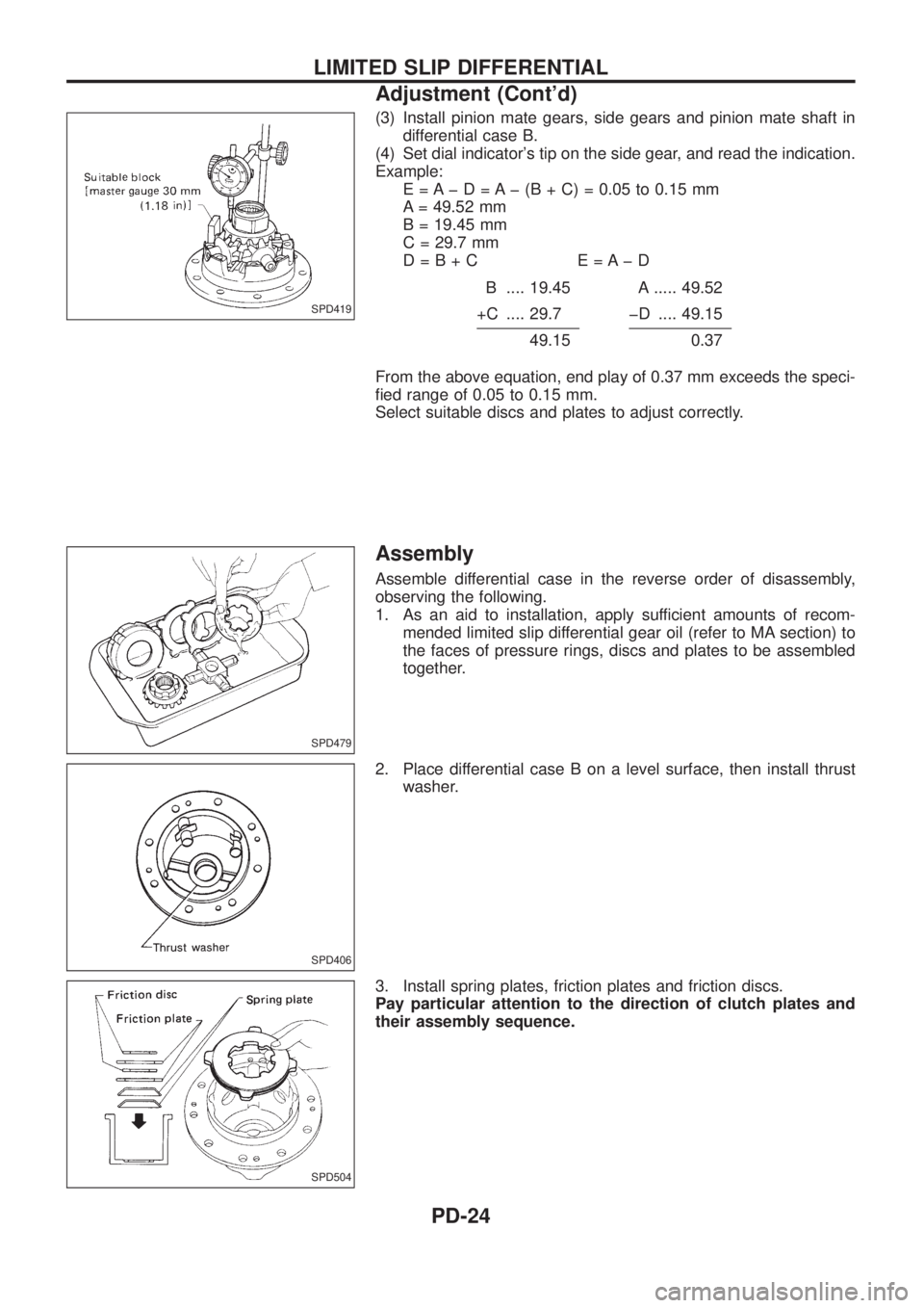
(3) Install pinion mate gears, side gears and pinion mate shaft in
differential case B.
(4) Set dial indicator's tip on the side gear, and read the indication.
Example:
E = A þ D = A þ (B + C) = 0.05 to 0.15 mm
A = 49.52 mm
B = 19.45 mm
C = 29.7 mm
D=B+C E=AþD
B .... 19.45 A ..... 49.52
+C .... 29.7 þD .... 49.15
49.150.37
From the above equation, end play of 0.37 mm exceeds the speci-
®ed range of 0.05 to 0.15 mm.
Select suitable discs and plates to adjust correctly.
Assembly
Assemble differential case in the reverse order of disassembly,
observing the following.
1. As an aid to installation, apply sufficient amounts of recom-
mended limited slip differential gear oil (refer to MA section) to
the faces of pressure rings, discs and plates to be assembled
together.
2. Place differential case B on a level surface, then install thrust
washer.
3. Install spring plates, friction plates and friction discs.
Pay particular attention to the direction of clutch plates and
their assembly sequence.
SPD419
SPD479
SPD406
SPD504
LIMITED SLIP DIFFERENTIAL
Adjustment (Cont'd)
PD-24
Page 1112 of 1226

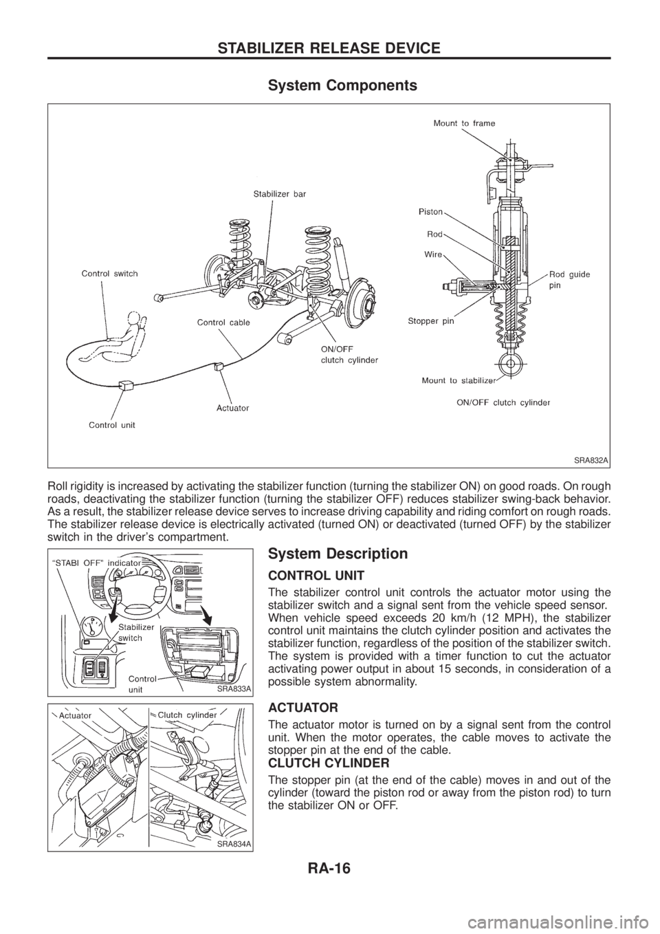
System Components
Roll rigidity is increased by activating the stabilizer function (turning the stabilizer ON) on good roads. On rough
roads, deactivating the stabilizer function (turning the stabilizer OFF) reduces stabilizer swing-back behavior.
As a result, the stabilizer release device serves to increase driving capability and riding comfort on rough roads.
The stabilizer release device is electrically activated (turned ON) or deactivated (turned OFF) by the stabilizer
switch in the driver's compartment.
System Description
CONTROL UNIT
The stabilizer control unit controls the actuator motor using the
stabilizer switch and a signal sent from the vehicle speed sensor.
When vehicle speed exceeds 20 km/h (12 MPH), the stabilizer
control unit maintains the clutch cylinder position and activates the
stabilizer function, regardless of the position of the stabilizer switch.
The system is provided with a timer function to cut the actuator
activating power output in about 15 seconds, in consideration of a
possible system abnormality.
ACTUATOR
The actuator motor is turned on by a signal sent from the control
unit. When the motor operates, the cable moves to activate the
stopper pin at the end of the cable.
CLUTCH CYLINDER
The stopper pin (at the end of the cable) moves in and out of the
cylinder (toward the piston rod or away from the piston rod) to turn
the stabilizer ON or OFF.
SRA832A
SRA833A
SRA834A
STABILIZER RELEASE DEVICE
RA-16
Page 1113 of 1226
Removal and Installation
1. Loosen the lock nut C, and loosen the A nut. Remove the cable
from the clutch cylinder.
CAUTION:
+Do not remove the B nut because this requires the inner
cable extension adjustment.
+Before installing the A and C nuts, use seal tape to wrap
the clutch cylinder thread area and cable thread area.
2. Remove the clamp and other fasteners which secure the cable.
3. Remove the stabilizer actuator connector.
4. Remove the stabilizer actuator.
5. Remove the clutch cylinder.
6. Before removing the stabilizer control unit, remove cluster lid C
and audio equipment. Refer to the BT section ``INSTRUMENT
PANEL''.
SRA835A
SRA836A
SRA837A
STABILIZER RELEASE DEVICE
RA-17
Page 1119 of 1226

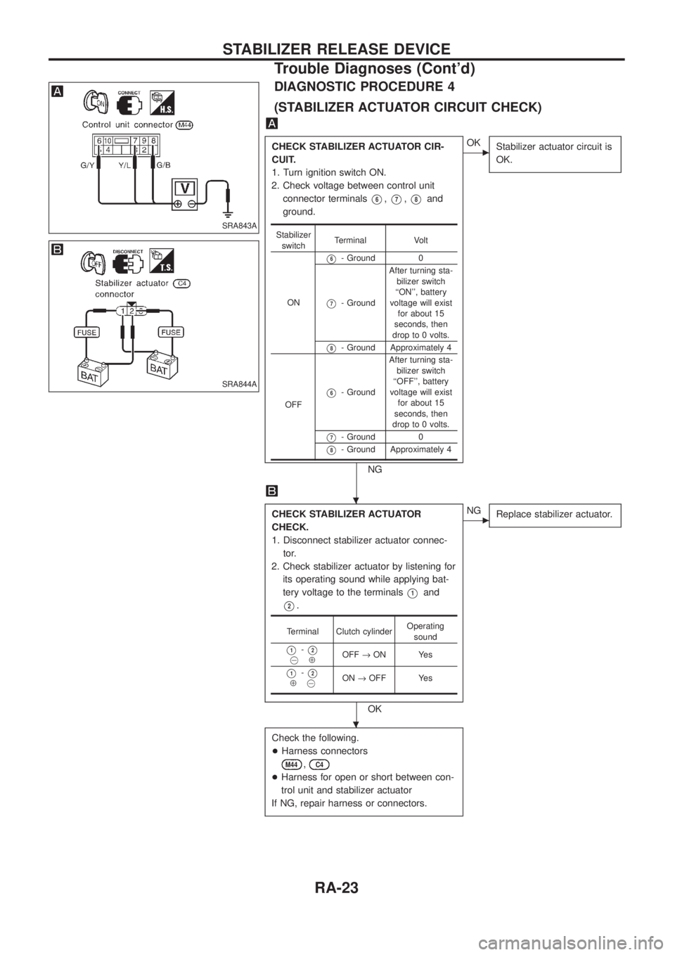
DIAGNOSTIC PROCEDURE 4
(STABILIZER ACTUATOR CIRCUIT CHECK)
CHECK STABILIZER ACTUATOR CIR-
CUIT.
1. Turn ignition switch ON.
2. Check voltage between control unit
connector terminals
V6,V7,V8and
ground.
NG
cOK
Stabilizer actuator circuit is
OK.
CHECK STABILIZER ACTUATOR
CHECK.
1. Disconnect stabilizer actuator connec-
tor.
2. Check stabilizer actuator by listening for
its operating sound while applying bat-
tery voltage to the terminals
V1and
V2.
OK
cNG
Replace stabilizer actuator.
Check the following.
+Harness connectors
M44,C4
+Harness for open or short between con-
trol unit and stabilizer actuator
If NG, repair harness or connectors.
Stabilizer
switchTerminal Volt
ON
V6- Ground 0
V7- GroundAfter turning sta-
bilizer switch
``ON'', battery
voltage will exist
for about 15
seconds, then
drop to 0 volts.
V8- Ground Approximately 4
OFF
V6- GroundAfter turning sta-
bilizer switch
``OFF'', battery
voltage will exist
for about 15
seconds, then
drop to 0 volts.
V7- Ground 0
V8- Ground Approximately 4
Terminal Clutch cylinderOperating
sound
V1-V2@ÅOFF®ON Yes
V1-V2Å@ON®OFF Yes
SRA843A
SRA844A
.
.
STABILIZER RELEASE DEVICE
Trouble Diagnoses (Cont'd)
RA-23