Page 316 of 1226
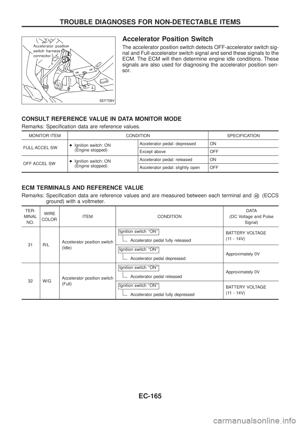
Accelerator Position Switch
The accelerator position switch detects OFF-accelerator switch sig-
nal and Full-accelerator switch signal and send these signals to the
ECM. The ECM will then determine engine idle conditions. These
signals are also used for diagnosing the accelerator position sen-
sor.
CONSULT REFERENCE VALUE IN DATA MONITOR MODE
Remarks: Speci®cation data are reference values.
MONITOR ITEM CONDITION SPECIFICATION
FULL ACCEL SW+Ignition switch: ON
(Engine stopped)Accelerator pedal: depressed ON
Except above OFF
OFF ACCEL SW+Ignition switch: ON
(Engine stopped)Accelerator pedal: released ON
Accelerator pedal: slightly open OFF
ECM TERMINALS AND REFERENCE VALUE
Remarks: Speci®cation data are reference values and are measured between each terminal andV43(ECCS
ground) with a voltmeter.
TER-
MINAL
NO.WIRE
COLORITEM CONDITIONDATA
(DC Voltage and Pulse
Signal)
31 R/LAccelerator position switch
(Idle)Ignition switch ``ON''
Accelerator pedal fully releasedBATTERY VOLTAGE
(11 - 14V)
Ignition switch ``ON''
Accelerator pedal depressedApproximately 0V
32 W/GAccelerator position switch
(Full)Ignition switch ``ON''
Accelerator pedal releasedApproximately 0V
Ignition switch ``ON''
Accelerator pedal fully depressedBATTERY VOLTAGE
(11 - 14V)
SEF708V
TROUBLE DIAGNOSES FOR NON-DETECTABLE ITEMS
EC-165
Page 318 of 1226
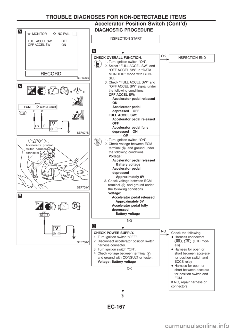
DIAGNOSTIC PROCEDURE
INSPECTION START
CHECK OVERALL FUNCTION.
1. Turn ignition switch ``ON''.
2. Select ``FULL ACCEL SW'' and
``OFF ACCEL SW'' in ``DATA
MONITOR'' mode with CON-
SULT.
3. Check ``FULL ACCEL SW'' and
``OFF ACCEL SW'' signal under
the following conditions.
OFF ACCEL SW:
Accelerator pedal released
ON
Accelerator pedal
depressed OFF
FULL ACCEL SW:
Accelerator pedal released
OFF
Accelerator pedal fully
depressed ON
--------------------------------------------------------------------------------------------------------------------------------------OR--------------------------------------------------------------------------------------------------------------------------------------
1. Turn ignition switch ``ON''.
2. Check voltage between ECM
terminal
V31and ground under
the following conditions.
Voltage:
Accelerator pedal released
Battery voltage
Accelerator pedal
depressed
Approximately 0V
3. Check voltage between ECM
terminal
V32and ground under
the following conditions.
Voltage:
Accelerator pedal released
Approximately 0V
Accelerator pedal fully
depressed
Battery voltage
NG
cOK
INSPECTION END
CHECK POWER SUPPLY.
1. Turn ignition switch ``OFF''.
2. Disconnect accelerator position switch
harness connector.
3. Turn ignition switch ``ON''.
4. Check voltage between terminal
V5
and ground with CONSULT or tester.
Voltage: Battery voltage
OK
cNG
Check the following.
+Harness connectors
M52,F7(LHD mod-
els)
+Harness for open or
short between accelera-
tor position switch and
ECCS relay
+Harness for open or
short between accelera-
tor position switch and
ECM
If NG, repair harness or
connectors.
jA
SEF626S
SEF627S
SEF708V
SEF786V
.
.
.
TROUBLE DIAGNOSES FOR NON-DETECTABLE ITEMS
Accelerator Position Switch (Cont'd)
EC-167
Page 322 of 1226
When the gear position is in ``N'', neutral position switch is ``ON''.
The ECM detects the position because the continuity of the line (the
``ON'' signal) exists.
CONSULT REFERENCE VALUE IN DATA MONITOR MODE
Remarks: Speci®cation data are reference values.
MONITOR ITEM CONDITION SPECIFICATION
P/N POSI SW+Ignition switch: ONShift lever: Neutral/Park ON
Except above OFF
ECM TERMINALS AND REFERENCE VALUE
Remarks: Speci®cation data are reference values and are measured between each terminal andV43(ECCS
ground) with a voltmeter.
TER-
MINAL
NO.WIRE
COLORITEM CONDITIONDATA
(DC Voltage and Pulse
Signal)
22 P/BInhibitor switch/
Neutral position switchIgnition switch ``ON''
Gear position is ``N'' or ``P'' (A/T models).Gear position is ``Neutral'' (M/T models).Approximately 0V
Ignition switch ``ON''
Except the above gear positionBATTERY VOLTAGE
(11 - 14V)
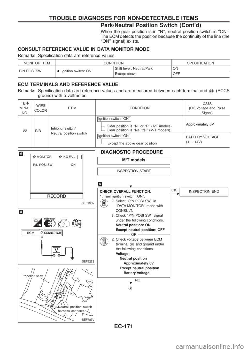
DIAGNOSTIC PROCEDURE
M/T models
INSPECTION START
CHECK OVERALL FUNCTION.
1. Turn ignition switch ``ON''.
2. Select ``P/N POSI SW'' in
``DATA MONITOR'' mode with
CONSULT.
3. Check ``P/N POSI SW'' signal
under the following conditions.
Neutral position: ON
Except neutral position: OFF
--------------------------------------------------------------------------------------------------------------------------------------OR--------------------------------------------------------------------------------------------------------------------------------------
2. Check voltage between ECM
terminal
V22and ground under
the following conditions.
Voltage:
Neutral position
Approximately 0V
Except neutral position
Battery voltage
NG
cOK
INSPECTION END
jA
SEF963N
SEF622S
SEF789V
.
.
TROUBLE DIAGNOSES FOR NON-DETECTABLE ITEMS
Park/Neutral Position Switch (Cont'd)
EC-171
Page 324 of 1226
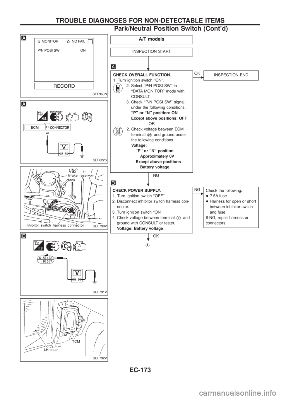
A/T models
INSPECTION START
CHECK OVERALL FUNCTION.
1. Turn ignition switch ``ON''.
2. Select ``P/N POSI SW'' in
``DATA MONITOR'' mode with
CONSULT.
3. Check ``P/N POSI SW'' signal
under the following conditions.
``P'' or ``N'' position: ON
Except above positions: OFF
--------------------------------------------------------------------------------------------------------------------------------------OR--------------------------------------------------------------------------------------------------------------------------------------
2. Check voltage between ECM
terminal
V22and ground under
the following conditions.
Voltage:
``P'' or ``N'' position
Approximately 0V
Except above positions
Battery voltage
NG
cOK
INSPECTION END
CHECK POWER SUPPLY.
1. Turn ignition switch ``OFF''.
2. Disconnect inhibitor switch harness con-
nector.
3. Turn ignition switch ``ON''.
4. Check voltage between terminal
V3and
ground with CONSULT or tester.
Voltage: Battery voltage
OK
cNG
Check the following.
+7.5A fuse
+Harness for open or short
between inhibitor switch
and fuse
If NG, repair harness or
connectors.
jA
SEF963N
SEF622S
SEF790V
SEF791V
SEF792V
.
.
.
TROUBLE DIAGNOSES FOR NON-DETECTABLE ITEMS
Park/Neutral Position Switch (Cont'd)
EC-173
Page 329 of 1226
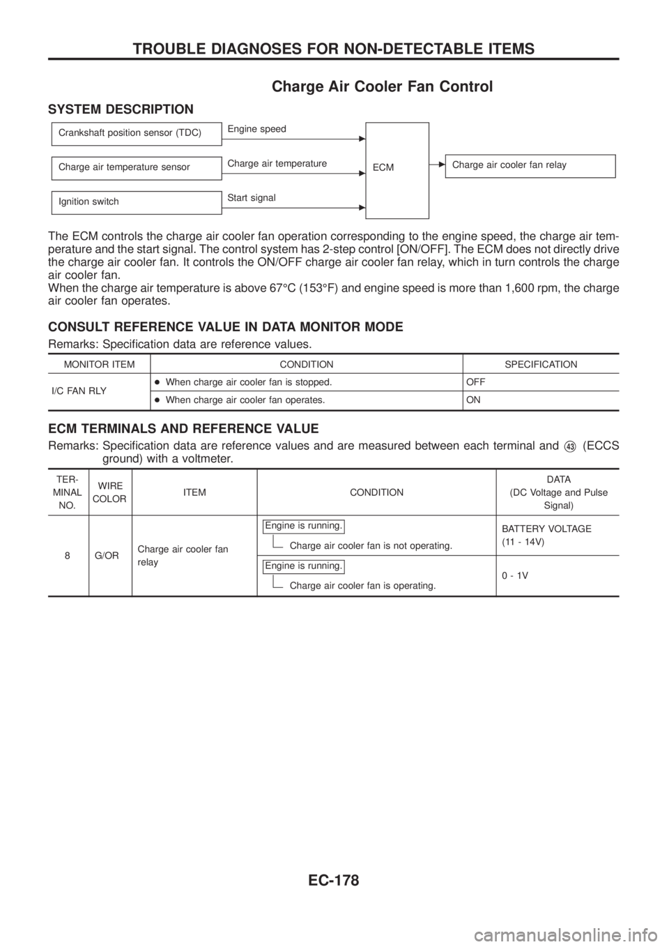
Charge Air Cooler Fan Control
SYSTEM DESCRIPTION
Crankshaft position sensor (TDC)cEngine speed
ECM
cCharge air cooler fan relayCharge air temperature sensorcCharge air temperature
Ignition switch
cStart signal
The ECM controls the charge air cooler fan operation corresponding to the engine speed, the charge air tem-
perature and the start signal. The control system has 2-step control [ON/OFF]. The ECM does not directly drive
the charge air cooler fan. It controls the ON/OFF charge air cooler fan relay, which in turn controls the charge
air cooler fan.
When the charge air temperature is above 67ÉC (153ÉF) and engine speed is more than 1,600 rpm, the charge
air cooler fan operates.
CONSULT REFERENCE VALUE IN DATA MONITOR MODE
Remarks: Speci®cation data are reference values.
MONITOR ITEM CONDITION SPECIFICATION
I/C FAN RLY+When charge air cooler fan is stopped. OFF
+When charge air cooler fan operates. ON
ECM TERMINALS AND REFERENCE VALUE
Remarks: Speci®cation data are reference values and are measured between each terminal andV43(ECCS
ground) with a voltmeter.
TER-
MINAL
NO.WIRE
COLORITEM CONDITIONDATA
(DC Voltage and Pulse
Signal)
8 G/ORCharge air cooler fan
relayEngine is running.
Charge air cooler fan is not operating.BATTERY VOLTAGE
(11 - 14V)
Engine is running.
Charge air cooler fan is operating.0-1V
TROUBLE DIAGNOSES FOR NON-DETECTABLE ITEMS
EC-178
Page 331 of 1226
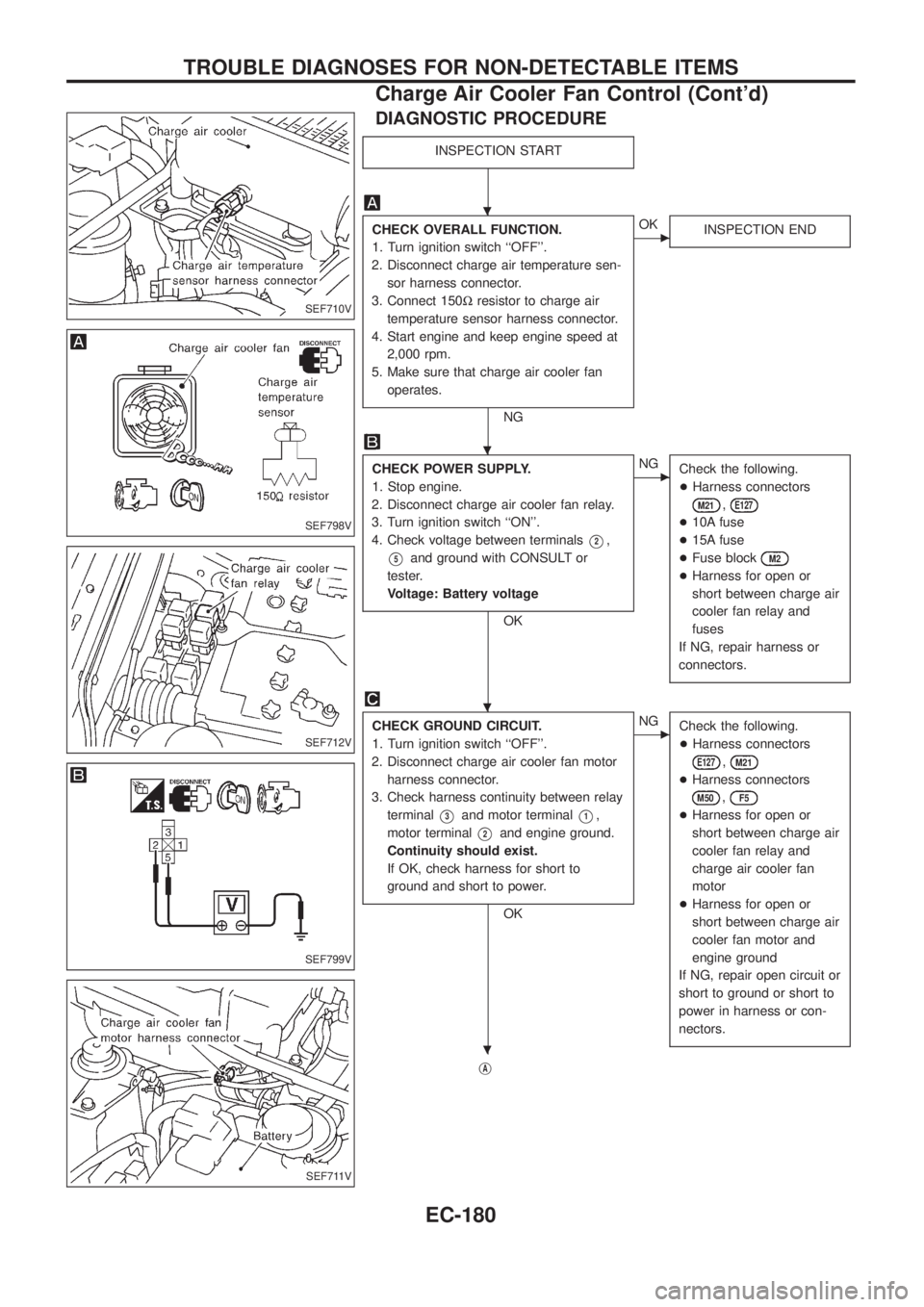
DIAGNOSTIC PROCEDURE
INSPECTION START
CHECK OVERALL FUNCTION.
1. Turn ignition switch ``OFF''.
2. Disconnect charge air temperature sen-
sor harness connector.
3. Connect 150Wresistor to charge air
temperature sensor harness connector.
4. Start engine and keep engine speed at
2,000 rpm.
5. Make sure that charge air cooler fan
operates.
NG
cOK
INSPECTION END
CHECK POWER SUPPLY.
1. Stop engine.
2. Disconnect charge air cooler fan relay.
3. Turn ignition switch ``ON''.
4. Check voltage between terminals
V2,
V5and ground with CONSULT or
tester.
Voltage: Battery voltage
OK
cNG
Check the following.
+Harness connectors
M21,E127
+10A fuse
+15A fuse
+Fuse block
M2
+Harness for open or
short between charge air
cooler fan relay and
fuses
If NG, repair harness or
connectors.
CHECK GROUND CIRCUIT.
1. Turn ignition switch ``OFF''.
2. Disconnect charge air cooler fan motor
harness connector.
3. Check harness continuity between relay
terminal
V3and motor terminalV1,
motor terminal
V2and engine ground.
Continuity should exist.
If OK, check harness for short to
ground and short to power.
OK
cNG
Check the following.
+Harness connectors
E127,M21
+Harness connectors
M50,F5
+Harness for open or
short between charge air
cooler fan relay and
charge air cooler fan
motor
+Harness for open or
short between charge air
cooler fan motor and
engine ground
If NG, repair open circuit or
short to ground or short to
power in harness or con-
nectors.
jA
SEF710V
SEF798V
SEF712V
SEF799V
SEF711V
.
.
.
.
TROUBLE DIAGNOSES FOR NON-DETECTABLE ITEMS
Charge Air Cooler Fan Control (Cont'd)
EC-180
Page 333 of 1226
COMPONENT INSPECTION
Charge air cooler fan relay
Check continuity between terminalsV3andV5.
Conditions Continuity
12V direct current supply between
terminals
V1andV2Ye s
No current supply No
If NG, replace relay.
Charge air cooler fan motor
1. Disconnect charge air cooler fan motor harness connector.
2. Supply charge air cooler fan motor terminals with battery volt-
age and check operation.
Charge air cooler fan motor should operate.
If NG, replace charge air cooler fan motor.
SEF511P
SEF802V
TROUBLE DIAGNOSES FOR NON-DETECTABLE ITEMS
Charge Air Cooler Fan Control (Cont'd)
EC-182
Page 334 of 1226
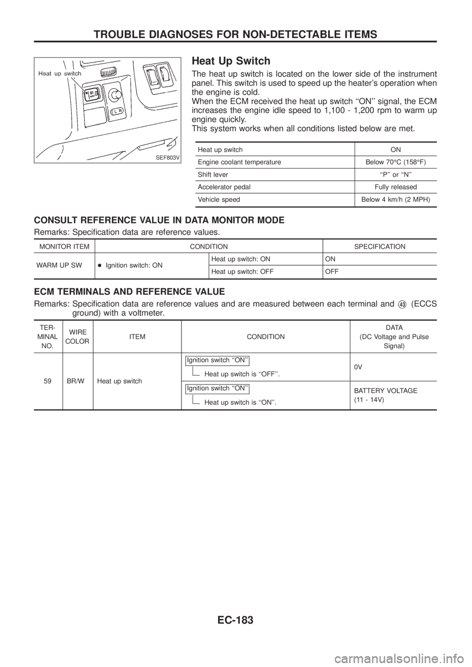
Heat Up Switch
The heat up switch is located on the lower side of the instrument
panel. This switch is used to speed up the heater's operation when
the engine is cold.
When the ECM received the heat up switch ``ON'' signal, the ECM
increases the engine idle speed to 1,100 - 1,200 rpm to warm up
engine quickly.
This system works when all conditions listed below are met.
Heat up switch ON
Engine coolant temperature Below 70ÉC (158ÉF)
Shift lever ``P'' or ``N''
Accelerator pedal Fully released
Vehicle speed Below 4 km/h (2 MPH)
CONSULT REFERENCE VALUE IN DATA MONITOR MODE
Remarks: Speci®cation data are reference values.
MONITOR ITEM CONDITION SPECIFICATION
WARM UP SW+Ignition switch: ONHeat up switch: ON ON
Heat up switch: OFF OFF
ECM TERMINALS AND REFERENCE VALUE
Remarks: Speci®cation data are reference values and are measured between each terminal andV43(ECCS
ground) with a voltmeter.
TER-
MINAL
NO.WIRE
COLORITEM CONDITIONDATA
(DC Voltage and Pulse
Signal)
59 BR/W Heat up switchIgnition switch ``ON''
Heat up switch is ``OFF''.0V
Ignition switch ``ON''
Heat up switch is ``ON''.BATTERY VOLTAGE
(11 - 14V)
SEF803V
TROUBLE DIAGNOSES FOR NON-DETECTABLE ITEMS
EC-183