2006 NISSAN PATROL battery
[x] Cancel search: batteryPage 302 of 1226
Glow Control System
SYSTEM DESCRIPTION
Crankshaft position sensor (TDC)cEngine speed
ECMcGlow relaycGlow plugs
Engine coolant temperature sensorcEngine coolant temperaturecGlow lamp
When engine coolant temperature is more than 90ÉC (194ÉF), the glow relay turns off, inactivating the quick-
glow control until coolant temperature drops below 70ÉC (158ÉF).
When coolant temperature is lower than 90ÉC (194ÉF):
+Ignition switch ON
After ignition switch has turned to ON, the glow relay turns ON for a certain period of time in relation to
engine coolant temperature, allowing current to ¯ow through glow plug.
+Cranking
The glow relay turns ON, allowing current to ¯ow through glow plug.
+Starting
After engine has started, current continues to ¯ow through glow plug (after-glow mode) for a certain period
in relation to engine coolant temperature.
When engine speed exceeds 2,400 rpm, current ¯ow through glow plug is interrupted.
The glow lamp turns ON for a certain period of time in relation to engine coolant temperature at the time glow
relay is turned ON.
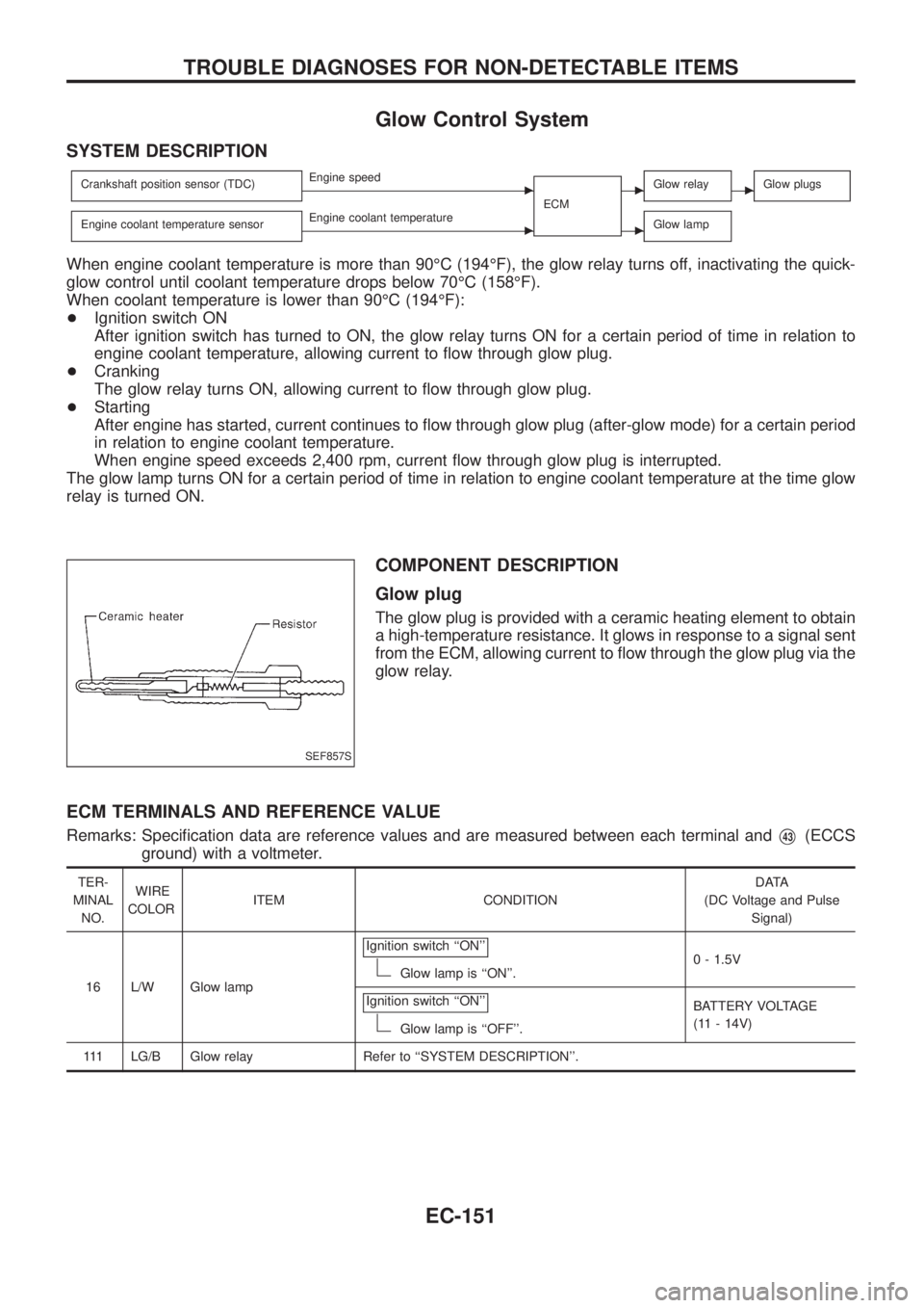
COMPONENT DESCRIPTION
Glow plug
The glow plug is provided with a ceramic heating element to obtain
a high-temperature resistance. It glows in response to a signal sent
from the ECM, allowing current to ¯ow through the glow plug via the
glow relay.
ECM TERMINALS AND REFERENCE VALUE
Remarks: Speci®cation data are reference values and are measured between each terminal andV43(ECCS
ground) with a voltmeter.
TER-
MINAL
NO.WIRE
COLORITEM CONDITIONDATA
(DC Voltage and Pulse
Signal)
16 L/W Glow lampIgnition switch ``ON''
Glow lamp is ``ON''.0 - 1.5V
Ignition switch ``ON''
Glow lamp is ``OFF''.BATTERY VOLTAGE
(11 - 14V)
111 LG/B Glow relay Refer to ``SYSTEM DESCRIPTION''.
SEF857S
TROUBLE DIAGNOSES FOR NON-DETECTABLE ITEMS
EC-151
Page 304 of 1226
DIAGNOSTIC PROCEDURE
INSPECTION START
Check fuel level, fuel supplying system,
starter motor, etc.
OK
cNG
Correct.
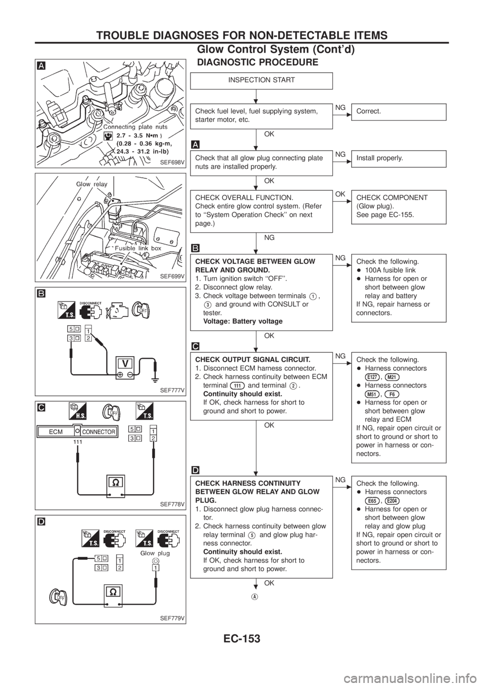
Check that all glow plug connecting plate
nuts are installed properly.
OK
cNG
Install properly.
CHECK OVERALL FUNCTION.
Check entire glow control system. (Refer
to ``System Operation Check'' on next
page.)
NG
cOK
CHECK COMPONENT
(Glow plug).
See page EC-155.
CHECK VOLTAGE BETWEEN GLOW
RELAY AND GROUND.
1. Turn ignition switch ``OFF''.
2. Disconnect glow relay.
3. Check voltage between terminals
V1,
V3and ground with CONSULT or
tester.
Voltage: Battery voltage
OK
cNG
Check the following.
+100A fusible link
+Harness for open or
short between glow
relay and battery
If NG, repair harness or
connectors.
CHECK OUTPUT SIGNAL CIRCUIT.
1. Disconnect ECM harness connector.
2. Check harness continuity between ECM
terminal
111and terminalV2.
Continuity should exist.
If OK, check harness for short to
ground and short to power.
OK
cNG
Check the following.
+Harness connectors
E127,M21
+Harness connectors
M51,F6
+Harness for open or
short between glow
relay and ECM
If NG, repair open circuit or
short to ground or short to
power in harness or con-
nectors.
CHECK HARNESS CONTINUITY
BETWEEN GLOW RELAY AND GLOW
PLUG.
1. Disconnect glow plug harness connec-
tor.
2. Check harness continuity between glow
relay terminal
V5and glow plug har-
ness connector.
Continuity should exist.
If OK, check harness for short to
ground and short to power.
OK
cNG
Check the following.
+Harness connectors
E65,E204
+Harness for open or
short between glow
relay and glow plug
If NG, repair open circuit or
short to ground or short to
power in harness or con-
nectors.
jA
SEF698V
SEF699V
SEF777V
SEF778V
SEF779V
.
.
.
.
.
.
.
TROUBLE DIAGNOSES FOR NON-DETECTABLE ITEMS
Glow Control System (Cont'd)
EC-153
Page 305 of 1226
jA
CHECK COMPONENTS
(Glow relay, Glow plug).
Refer to ``COMPONENT INSPECTION'',
EC-155.
OK
cNG
Replace malfunctioning
component(s).
Disconnect and reconnect harness connec-
tors in the circuit. Then retest.
Trouble is not ®xed.
Check ECM pin terminals for damage and
check the connection of ECM harness con-
nector. Reconnect ECM harness connector
and retest.
INSPECTION END
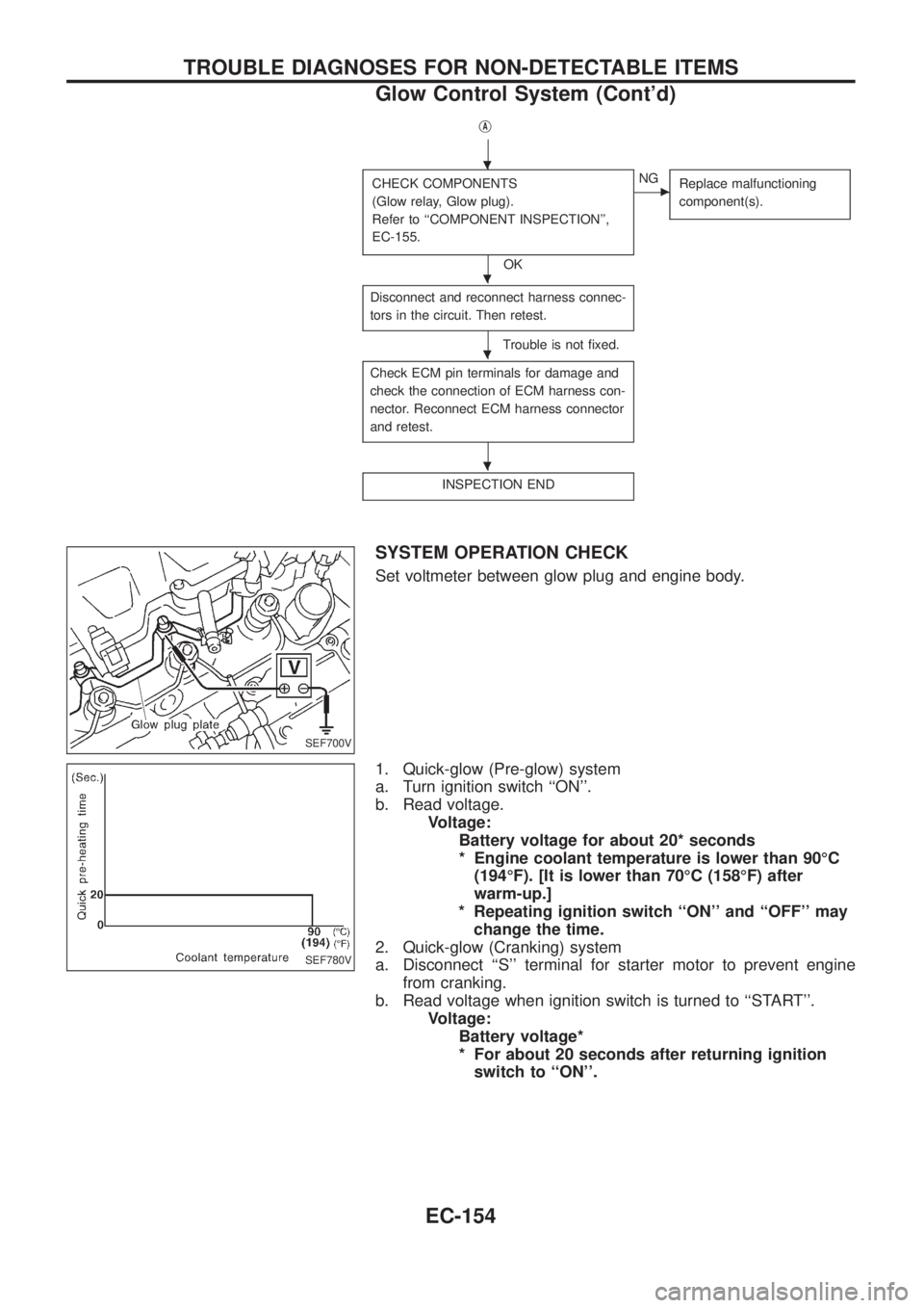
SYSTEM OPERATION CHECK
Set voltmeter between glow plug and engine body.
1. Quick-glow (Pre-glow) system
a. Turn ignition switch ``ON''.
b. Read voltage.
Voltage:
Battery voltage for about 20* seconds
* Engine coolant temperature is lower than 90ÉC
(194ÉF). [It is lower than 70ÉC (158ÉF) after
warm-up.]
* Repeating ignition switch ``ON'' and ``OFF'' may
change the time.
2. Quick-glow (Cranking) system
a. Disconnect ``S'' terminal for starter motor to prevent engine
from cranking.
b. Read voltage when ignition switch is turned to ``START''.
Voltage:
Battery voltage*
* For about 20 seconds after returning ignition
switch to ``ON''.
SEF700V
SEF780V
.
.
.
.
TROUBLE DIAGNOSES FOR NON-DETECTABLE ITEMS
Glow Control System (Cont'd)
EC-154
Page 306 of 1226
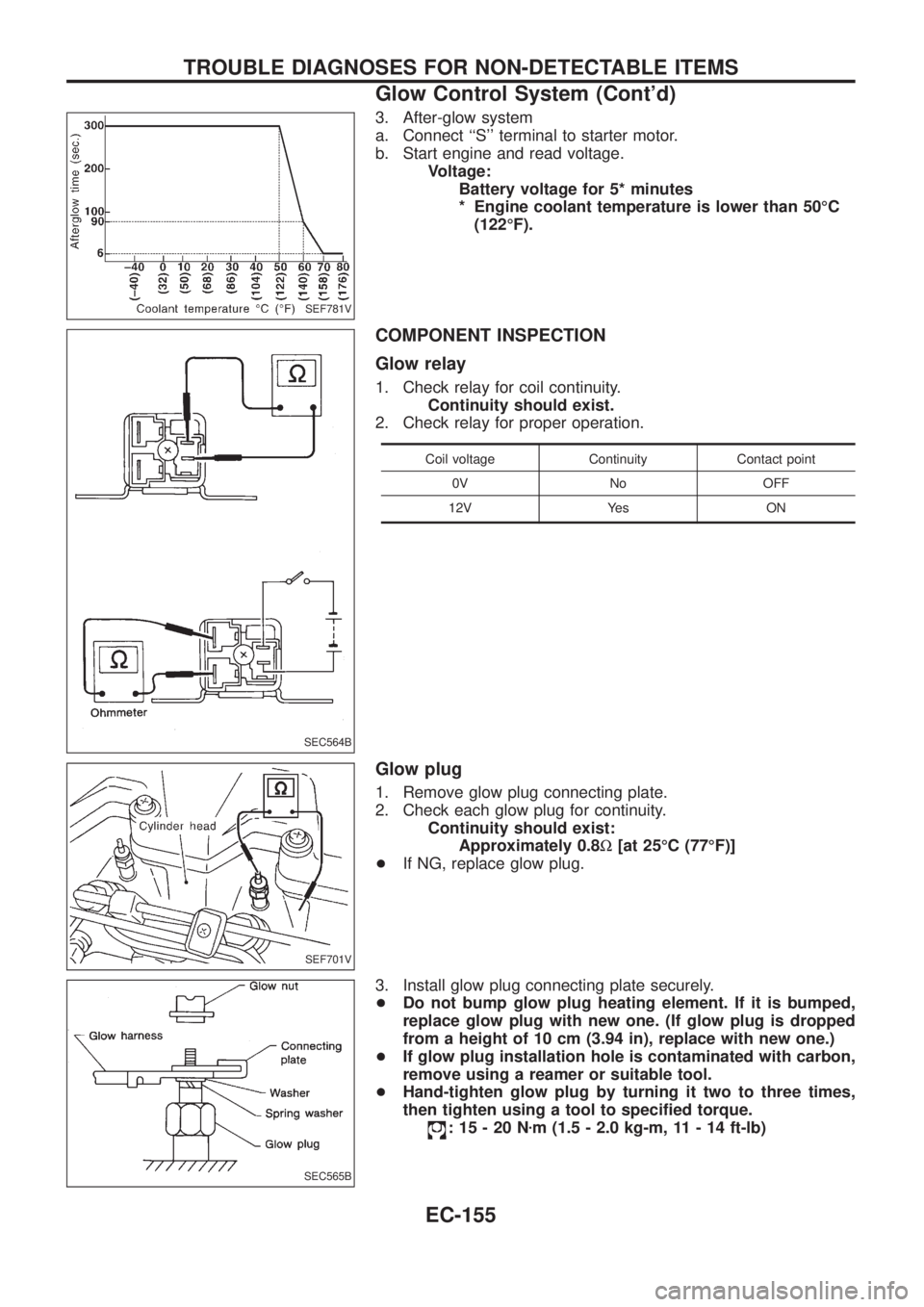
3. After-glow system
a. Connect ``S'' terminal to starter motor.
b. Start engine and read voltage.
Voltage:
Battery voltage for 5* minutes
* Engine coolant temperature is lower than 50ÉC
(122ÉF).
COMPONENT INSPECTION
Glow relay
1. Check relay for coil continuity.
Continuity should exist.
2. Check relay for proper operation.
Coil voltage Continuity Contact point
0V No OFF
12V Yes ON
Glow plug
1. Remove glow plug connecting plate.
2. Check each glow plug for continuity.
Continuity should exist:
Approximately 0.8W[at 25ÉC (77ÉF)]
+If NG, replace glow plug.
3. Install glow plug connecting plate securely.
+Do not bump glow plug heating element. If it is bumped,
replace glow plug with new one. (If glow plug is dropped
from a height of 10 cm (3.94 in), replace with new one.)
+If glow plug installation hole is contaminated with carbon,
remove using a reamer or suitable tool.
+Hand-tighten glow plug by turning it two to three times,
then tighten using a tool to speci®ed torque.
:15-20Nzm (1.5 - 2.0 kg-m, 11 - 14 ft-lb)
SEF781V
SEC564B
SEF701V
SEC565B
TROUBLE DIAGNOSES FOR NON-DETECTABLE ITEMS
Glow Control System (Cont'd)
EC-155
Page 308 of 1226
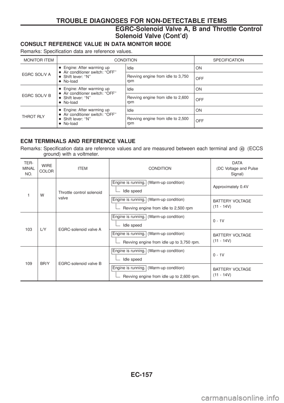
CONSULT REFERENCE VALUE IN DATA MONITOR MODE
Remarks: Speci®cation data are reference values.
MONITOR ITEM CONDITION SPECIFICATION
EGRC SOL/V A+Engine: After warming up
+Air conditioner switch: ``OFF''
+Shift lever: ``N''
+No-loadIdle ON
Revving engine from idle to 3,750
rpmOFF
EGRC SOL/V B+Engine: After warming up
+Air conditioner switch: ``OFF''
+Shift lever: ``N''
+No-loadIdle ON
Revving engine from idle to 2,600
rpmOFF
THROT RLY+Engine: After warming up
+Air conditioner switch: ``OFF''
+Shift lever: ``N''
+No-loadIdle ON
Revving engine from idle to 2,500
rpmOFF
ECM TERMINALS AND REFERENCE VALUE
Remarks: Speci®cation data are reference values and are measured between each terminal andV43(ECCS
ground) with a voltmeter.
TER-
MINAL
NO.WIRE
COLORITEM CONDITIONDATA
(DC Voltage and Pulse
Signal)
1WThrottle control solenoid
valveEngine is running.
(Warm-up condition)
Idle speedApproximately 0.4V
Engine is running.
(Warm-up condition)
Revving engine from idle to 2,500 rpmBATTERY VOLTAGE
(11 - 14V)
103 L/Y EGRC-solenoid valve AEngine is running.
(Warm-up condition)
Idle speed0-1V
Engine is running.
(Warm-up condition)
Revving engine from idle up to 3,750 rpm.BATTERY VOLTAGE
(11 - 14V)
109 BR/Y EGRC-solenoid valve BEngine is running.
(Warm-up condition)
Idle speed0-1V
Engine is running.
(Warm-up condition)
Revving engine from idle up to 2,600 rpm.BATTERY VOLTAGE
(11 - 14V)
TROUBLE DIAGNOSES FOR NON-DETECTABLE ITEMS
EGRC-Solenoid Valve A, B and Throttle Control
Solenoid Valve (Cont'd)
EC-157
Page 311 of 1226
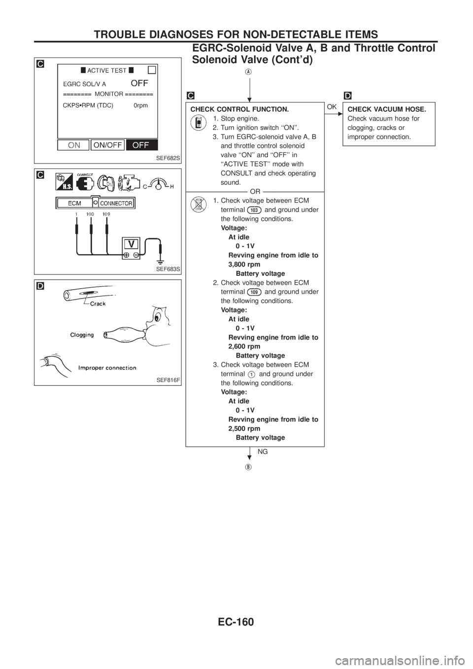
jA
CHECK CONTROL FUNCTION.
1. Stop engine.
2. Turn ignition switch ``ON''.
3. Turn EGRC-solenoid valve A, B
and throttle control solenoid
valve ``ON'' and ``OFF'' in
``ACTIVE TEST'' mode with
CONSULT and check operating
sound.
--------------------------------------------------------------------------------------------------------------------------------------OR--------------------------------------------------------------------------------------------------------------------------------------
1. Check voltage between ECM
terminal
103and ground under
the following conditions.
Voltage:
At idle
0-1V
Revving engine from idle to
3,800 rpm
Battery voltage
2. Check voltage between ECM
terminal
109and ground under
the following conditions.
Voltage:
At idle
0-1V
Revving engine from idle to
2,600 rpm
Battery voltage
3. Check voltage between ECM
terminal
V1and ground under
the following conditions.
Voltage:
At idle
0-1V
Revving engine from idle to
2,500 rpm
Battery voltage
NG
cOK
CHECK VACUUM HOSE.
Check vacuum hose for
clogging, cracks or
improper connection.
jB
SEF682S
SEF683S
SEF816F
.
.
TROUBLE DIAGNOSES FOR NON-DETECTABLE ITEMS
EGRC-Solenoid Valve A, B and Throttle Control
Solenoid Valve (Cont'd)
EC-160
Page 312 of 1226
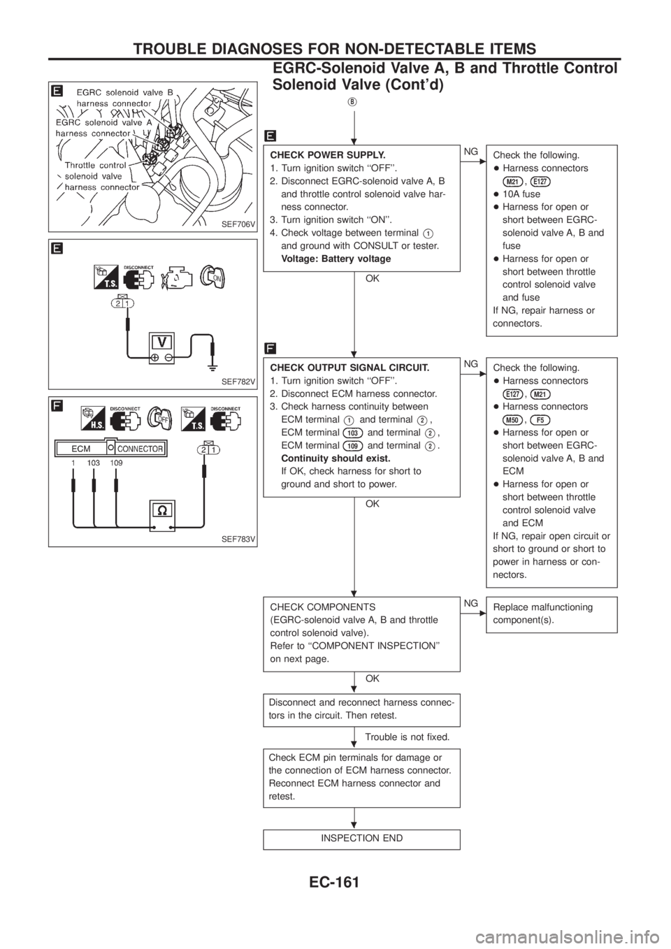
jB
CHECK POWER SUPPLY.
1. Turn ignition switch ``OFF''.
2. Disconnect EGRC-solenoid valve A, B
and throttle control solenoid valve har-
ness connector.
3. Turn ignition switch ``ON''.
4. Check voltage between terminal
V1
and ground with CONSULT or tester.
Voltage: Battery voltage
OK
cNG
Check the following.
+Harness connectors
M21,E127
+10A fuse
+Harness for open or
short between EGRC-
solenoid valve A, B and
fuse
+Harness for open or
short between throttle
control solenoid valve
and fuse
If NG, repair harness or
connectors.
CHECK OUTPUT SIGNAL CIRCUIT.
1. Turn ignition switch ``OFF''.
2. Disconnect ECM harness connector.
3. Check harness continuity between
ECM terminal
V1and terminalV2,
ECM terminal
103and terminalV2,
ECM terminal
109and terminalV2.
Continuity should exist.
If OK, check harness for short to
ground and short to power.
OK
cNG
Check the following.
+Harness connectors
E127,M21
+Harness connectors
M50,F5
+Harness for open or
short between EGRC-
solenoid valve A, B and
ECM
+Harness for open or
short between throttle
control solenoid valve
and ECM
If NG, repair open circuit or
short to ground or short to
power in harness or con-
nectors.
CHECK COMPONENTS
(EGRC-solenoid valve A, B and throttle
control solenoid valve).
Refer to ``COMPONENT INSPECTION''
on next page.
OK
cNG
Replace malfunctioning
component(s).
Disconnect and reconnect harness connec-
tors in the circuit. Then retest.
Trouble is not ®xed.
Check ECM pin terminals for damage or
the connection of ECM harness connector.
Reconnect ECM harness connector and
retest.
INSPECTION END
SEF706V
SEF782V
SEF783V
.
.
.
.
.
.
TROUBLE DIAGNOSES FOR NON-DETECTABLE ITEMS
EGRC-Solenoid Valve A, B and Throttle Control
Solenoid Valve (Cont'd)
EC-161
Page 315 of 1226
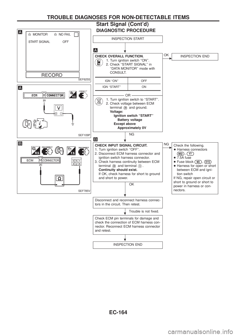
DIAGNOSTIC PROCEDURE
INSPECTION START
CHECK OVERALL FUNCTION.
1. Turn ignition switch ``ON''.
2. Check ``START SIGNAL'' in
``DATA MONITOR'' mode with
CONSULT.
--------------------------------------------------------------------------------------------------------------------------------------OR--------------------------------------------------------------------------------------------------------------------------------------
1. Turn ignition switch to ``START''.
2. Check voltage between ECM
terminal
V20and ground.
Voltage:
Ignition switch ``START''
Battery voltage
Except above
Approximately 0V
NG
cOK
INSPECTION END
CHECK INPUT SIGNAL CIRCUIT.
1. Turn ignition switch ``OFF''.
2. Disconnect ECM harness connector and
ignition switch harness connector.
3. Check harness continuity between ECM
terminal
V20and terminalV6.
Continuity should exist.
If OK, check harness for short to ground
and short to power.
OK
cNG
Check the following.
+Harness connectors
M52,F7
+7.5A fuse
+Fuse block
M3,E112
+Harness for open or short
between ECM and igni-
tion switch
If NG, repair open circuit or
short to ground or short to
power in harness or con-
nectors.
Disconnect and reconnect harness connec-
tors in the circuit. Then retest.
Trouble is not ®xed.
Check ECM pin terminals for damage and
check the connection of ECM harness con-
nector. Reconnect ECM harness connector
and retest.
INSPECTION END
IGN ``ON'' OFF
IGN ``START'' ONSEF625S
SEF109P
SEF785V
.
.
.
.
.
TROUBLE DIAGNOSES FOR NON-DETECTABLE ITEMS
Start Signal (Cont'd)
EC-164