2006 NISSAN PATROL battery
[x] Cancel search: batteryPage 255 of 1226
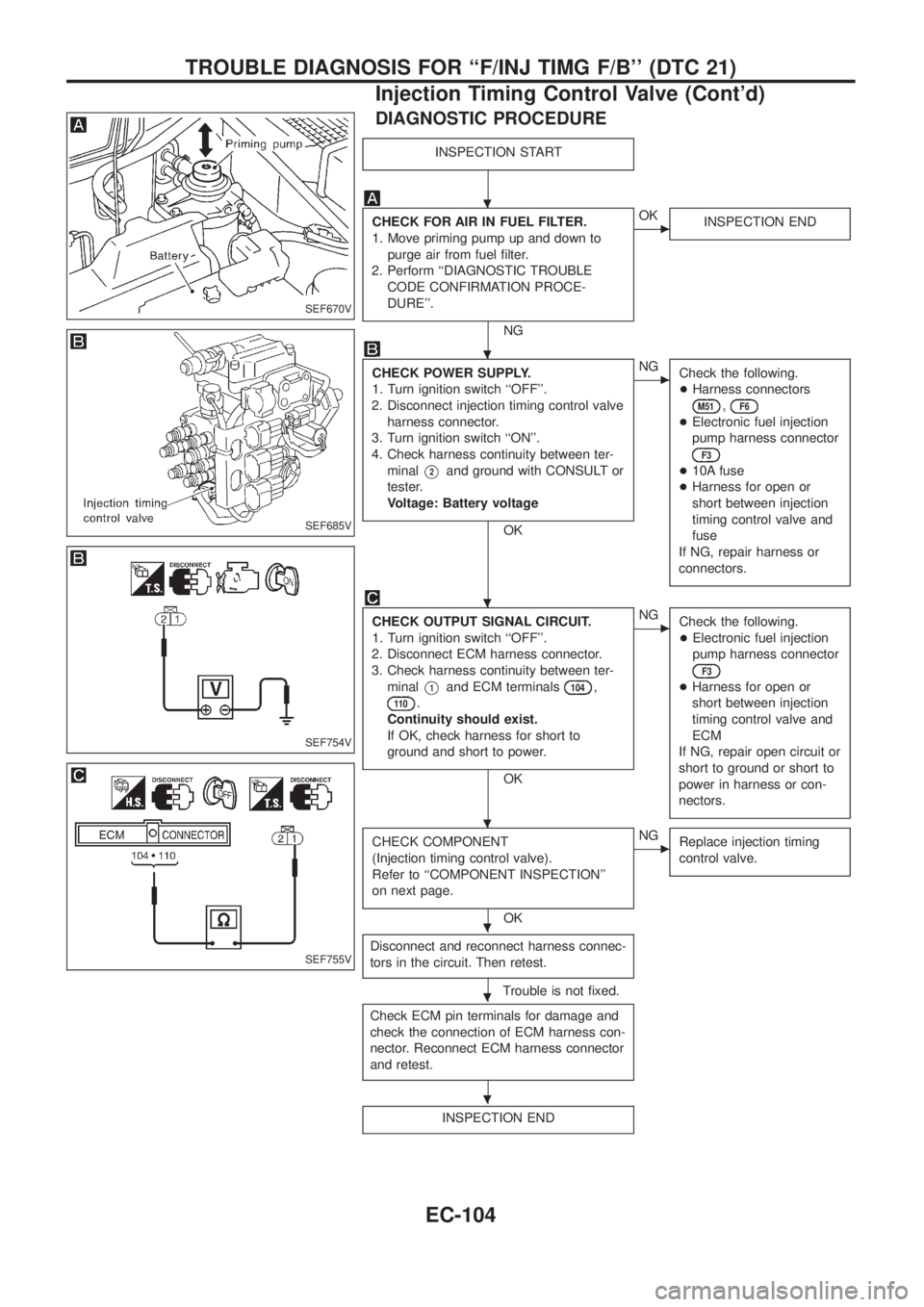
DIAGNOSTIC PROCEDURE
INSPECTION START
CHECK FOR AIR IN FUEL FILTER.
1. Move priming pump up and down to
purge air from fuel ®lter.
2. Perform ``DIAGNOSTIC TROUBLE
CODE CONFIRMATION PROCE-
DURE''.
NG
cOK
INSPECTION END
CHECK POWER SUPPLY.
1. Turn ignition switch ``OFF''.
2. Disconnect injection timing control valve
harness connector.
3. Turn ignition switch ``ON''.
4. Check harness continuity between ter-
minal
V2and ground with CONSULT or
tester.
Voltage: Battery voltage
OK
cNG
Check the following.
+Harness connectors
M51,F6
+Electronic fuel injection
pump harness connector
F3
+10A fuse
+Harness for open or
short between injection
timing control valve and
fuse
If NG, repair harness or
connectors.
CHECK OUTPUT SIGNAL CIRCUIT.
1. Turn ignition switch ``OFF''.
2. Disconnect ECM harness connector.
3. Check harness continuity between ter-
minal
V1and ECM terminals104,
11 0.
Continuity should exist.
If OK, check harness for short to
ground and short to power.
OK
cNG
Check the following.
+Electronic fuel injection
pump harness connector
F3
+Harness for open or
short between injection
timing control valve and
ECM
If NG, repair open circuit or
short to ground or short to
power in harness or con-
nectors.
CHECK COMPONENT
(Injection timing control valve).
Refer to ``COMPONENT INSPECTION''
on next page.
OK
cNG
Replace injection timing
control valve.
Disconnect and reconnect harness connec-
tors in the circuit. Then retest.
Trouble is not ®xed.
Check ECM pin terminals for damage and
check the connection of ECM harness con-
nector. Reconnect ECM harness connector
and retest.
INSPECTION END
SEF670V
SEF685V
SEF754V
SEF755V
.
.
.
.
.
.
.
TROUBLE DIAGNOSIS FOR ``F/INJ TIMG F/B'' (DTC 21)
Injection Timing Control Valve (Cont'd)
EC-104
Page 257 of 1226
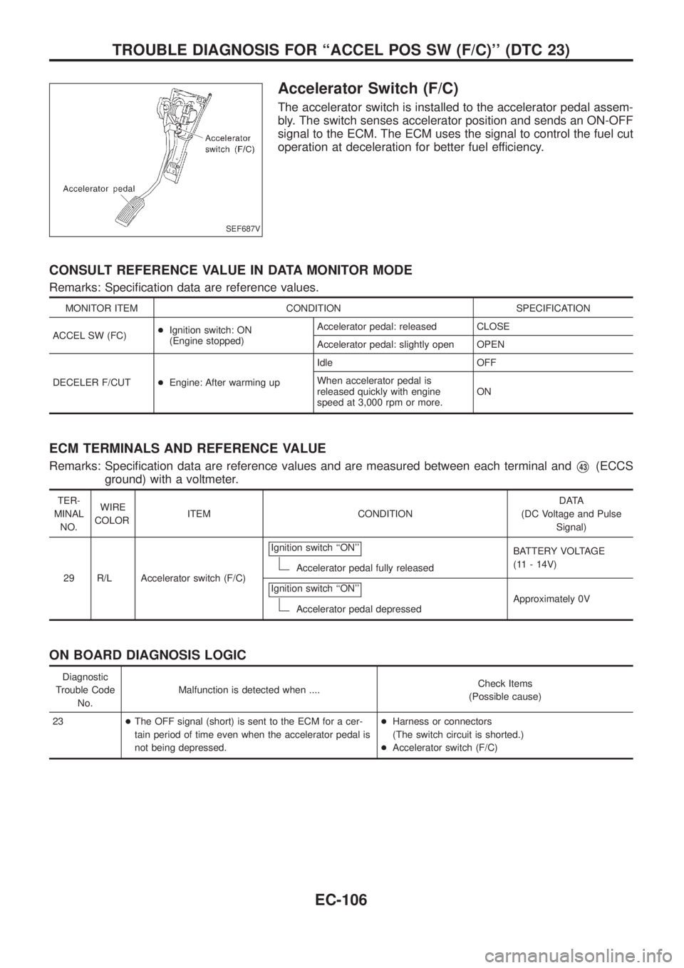
Accelerator Switch (F/C)
The accelerator switch is installed to the accelerator pedal assem-
bly. The switch senses accelerator position and sends an ON-OFF
signal to the ECM. The ECM uses the signal to control the fuel cut
operation at deceleration for better fuel efficiency.
CONSULT REFERENCE VALUE IN DATA MONITOR MODE
Remarks: Speci®cation data are reference values.
MONITOR ITEM CONDITION SPECIFICATION
ACCEL SW (FC)+Ignition switch: ON
(Engine stopped)Accelerator pedal: released CLOSE
Accelerator pedal: slightly open OPEN
DECELER F/CUT+Engine: After warming upIdle OFF
When accelerator pedal is
released quickly with engine
speed at 3,000 rpm or more.ON
ECM TERMINALS AND REFERENCE VALUE
Remarks: Speci®cation data are reference values and are measured between each terminal andV43(ECCS
ground) with a voltmeter.
TER-
MINAL
NO.WIRE
COLORITEM CONDITIONDATA
(DC Voltage and Pulse
Signal)
29 R/L Accelerator switch (F/C)Ignition switch ``ON''
Accelerator pedal fully releasedBATTERY VOLTAGE
(11 - 14V)
Ignition switch ``ON''
Accelerator pedal depressedApproximately 0V
ON BOARD DIAGNOSIS LOGIC
Diagnostic
Trouble Code
No.Malfunction is detected when ....Check Items
(Possible cause)
23+The OFF signal (short) is sent to the ECM for a cer-
tain period of time even when the accelerator pedal is
not being depressed.+Harness or connectors
(The switch circuit is shorted.)
+Accelerator switch (F/C)
SEF687V
TROUBLE DIAGNOSIS FOR ``ACCEL POS SW (F/C)'' (DTC 23)
EC-106
Page 260 of 1226
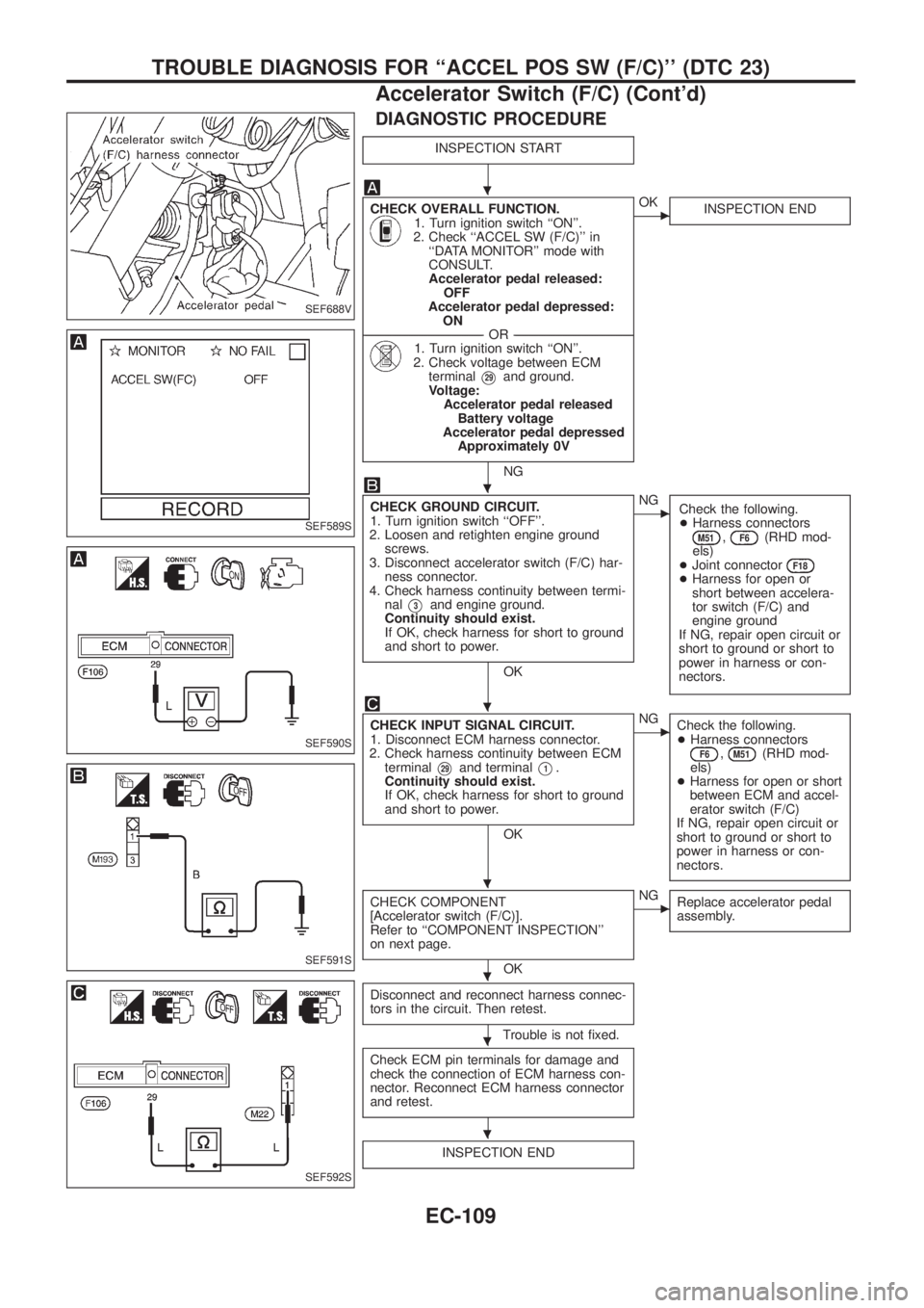
DIAGNOSTIC PROCEDURE
INSPECTION START
CHECK OVERALL FUNCTION.1. Turn ignition switch ``ON''.
2. Check ``ACCEL SW (F/C)'' in
``DATA MONITOR'' mode with
CONSULT.
Accelerator pedal released:
OFF
Accelerator pedal depressed:
ON
--------------------------------------------------------------------------------------------------------------------------------------OR--------------------------------------------------------------------------------------------------------------------------------------
1. Turn ignition switch ``ON''.
2. Check voltage between ECM
terminal
V29and ground.
Voltage:
Accelerator pedal released
Battery voltage
Accelerator pedal depressed
Approximately 0V
NG
cOK
INSPECTION END
CHECK GROUND CIRCUIT.
1. Turn ignition switch ``OFF''.
2. Loosen and retighten engine ground
screws.
3. Disconnect accelerator switch (F/C) har-
ness connector.
4. Check harness continuity between termi-
nal
V3and engine ground.
Continuity should exist.
If OK, check harness for short to ground
and short to power.
OK
cNG
Check the following.
+Harness connectors
M51,F6(RHD mod-
els)
+Joint connector
F18+Harness for open or
short between accelera-
tor switch (F/C) and
engine ground
If NG, repair open circuit or
short to ground or short to
power in harness or con-
nectors.
CHECK INPUT SIGNAL CIRCUIT.
1. Disconnect ECM harness connector.
2. Check harness continuity between ECM
terminal
V29and terminalV1.
Continuity should exist.
If OK, check harness for short to ground
and short to power.
OK
cNG
Check the following.
+Harness connectors
F6,M51(RHD mod-
els)
+Harness for open or short
between ECM and accel-
erator switch (F/C)
If NG, repair open circuit or
short to ground or short to
power in harness or con-
nectors.
CHECK COMPONENT
[Accelerator switch (F/C)].
Refer to ``COMPONENT INSPECTION''
on next page.
OK
cNG
Replace accelerator pedal
assembly.
Disconnect and reconnect harness connec-
tors in the circuit. Then retest.
Trouble is not ®xed.
Check ECM pin terminals for damage and
check the connection of ECM harness con-
nector. Reconnect ECM harness connector
and retest.
INSPECTION END
SEF688V
SEF589S
SEF590S
SEF591S
SEF592S
.
.
.
.
.
.
.
TROUBLE DIAGNOSIS FOR ``ACCEL POS SW (F/C)'' (DTC 23)
Accelerator Switch (F/C) (Cont'd)
EC-109
Page 264 of 1226
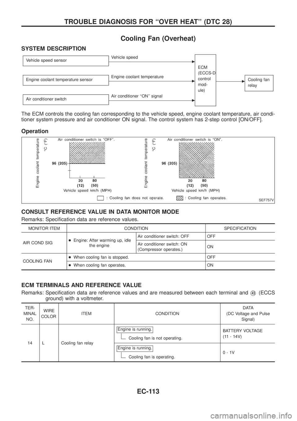
Cooling Fan (Overheat)
SYSTEM DESCRIPTION
Vehicle speed sensorcVehicle speed
ECM
(ECCS-D
control
mod-
ule)
cCooling fan
relayEngine coolant temperature sensorcEngine coolant temperature
Air conditioner switch
cAir conditioner ``ON'' signal
The ECM controls the cooling fan corresponding to the vehicle speed, engine coolant temperature, air condi-
tioner system pressure and air conditioner ON signal. The control system has 2-step control [ON/OFF].
Operation
CONSULT REFERENCE VALUE IN DATA MONITOR MODE
Remarks: Speci®cation data are reference values.
MONITOR ITEM CONDITION SPECIFICATION
AIR COND SIG+Engine: After warming up, idle
the engineAir conditioner switch: OFF OFF
Air conditioner switch: ON
(Compressor operates.)ON
COOLING FAN+When cooling fan is stopped. OFF
+When cooling fan operates. ON
ECM TERMINALS AND REFERENCE VALUE
Remarks: Speci®cation data are reference values and are measured between each terminal andV43(ECCS
ground) with a voltmeter.
TER-
MINAL
NO.WIRE
COLORITEM CONDITIONDATA
(DC Voltage and Pulse
Signal)
14 L Cooling fan relayEngine is running.
Cooling fan is not operating.BATTERY VOLTAGE
(11 - 14V)
Engine is running.
Cooling fan is operating.0-1V
SEF757V
TROUBLE DIAGNOSIS FOR ``OVER HEAT'' (DTC 28)
EC-113
Page 265 of 1226

TER-
MINAL
NO.WIRE
COLORITEM CONDITIONDATA
(DC Voltage and Pulse
Signal)
15 Y/L Air conditioner relayEngine is running.
Air conditioner switch is ``OFF''.BATTERY VOLTAGE
(11 - 14V)
Engine is running.
Both air conditioner switch and blower fan
switch are ``ON''.
(Compressor is operating.)0-1V
ON BOARD DIAGNOSIS LOGIC
This diagnosis continuously monitors the engine coolant temperature.
If the cooling fan or another component in the cooling system malfunctions, engine coolant temperature will
rise.
When the engine coolant temperature reaches an abnormally high temperature condition, a malfunction is
indicated.
Diagnostic Trouble
Code No.Malfunction is detected when ...Check Items
(Possible Cause)
28+Cooling fan does not operate properly (Overheat).
+Cooling fan system does not operate properly (Over-
heat).
+Engine coolant was not added to the system using
the proper ®lling method.+Harness or connectors
(The cooling fan circuit is open or shorted.)
+Cooling fan
+Radiator hose
+Radiator
+Radiator cap
+Water pump
+Thermostat
+Fan belt
+Engine coolant temperature sensor
For more information, refer to ``MAIN 12
CAUSES OF OVERHEATING'', EC-120.
CAUTION:
When a malfunction is indicated, be sure to replace the coolant following the procedure in the MA
section (``Changing Engine Coolant'', ``ENGINE MAINTENANCE''). Also, replace the engine oil.
a. Fill radiator with coolant up to speci®ed level with a ®lling speed of 2 liters per minute. Be sure to
use coolant with the proper mixture ratio. Refer to MA section (``Anti-freeze Coolant Mixture Ratio'',
``RECOMMENDED FLUIDS AND LUBRICANTS'').
b. After re®lling coolant, run engine to ensure that no water-¯ow noise is emitted.
TROUBLE DIAGNOSIS FOR ``OVER HEAT'' (DTC 28)
Cooling Fan (Overheat) (Cont'd)
EC-114
Page 268 of 1226
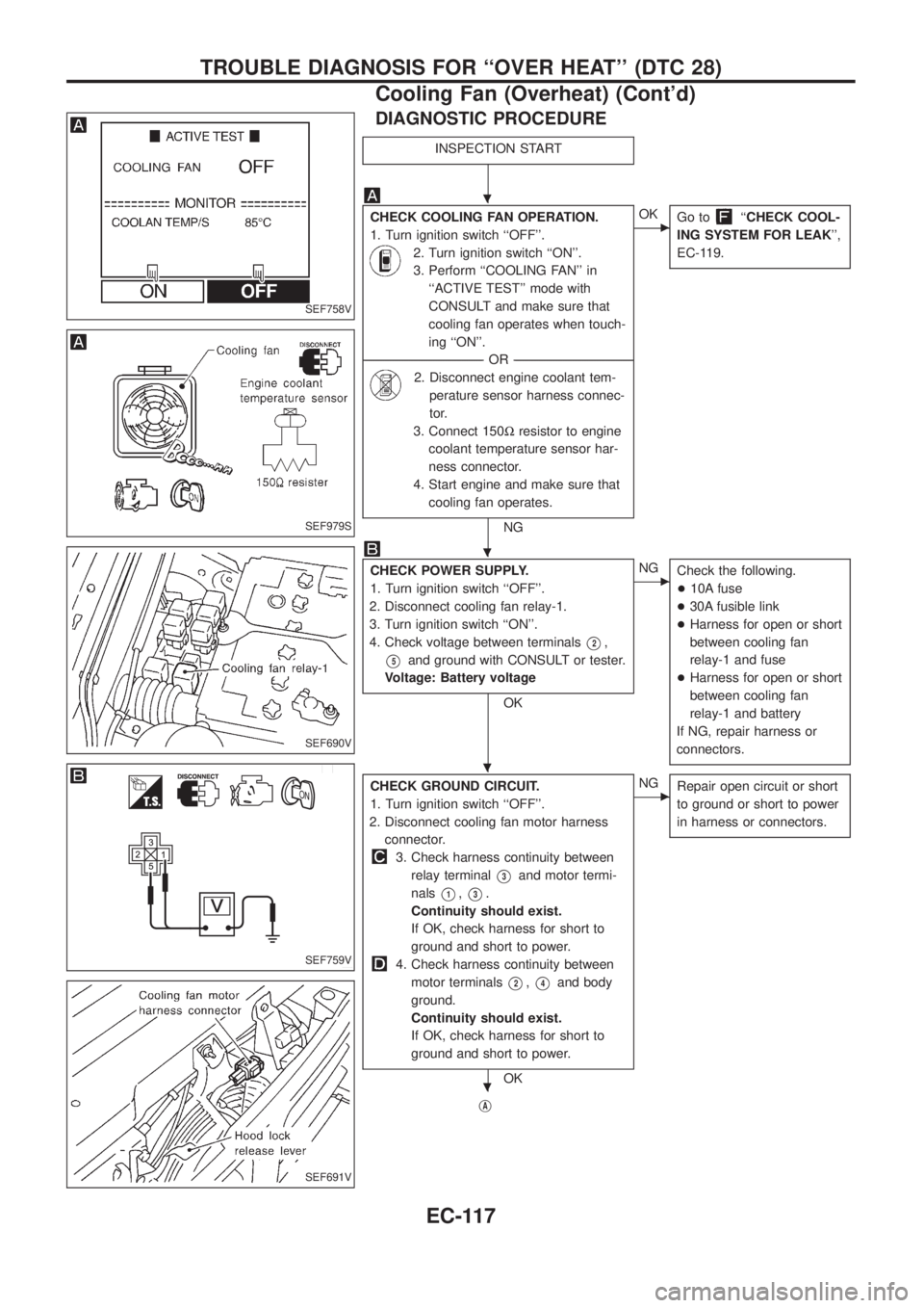
DIAGNOSTIC PROCEDURE
INSPECTION START
CHECK COOLING FAN OPERATION.
1. Turn ignition switch ``OFF''.
2. Turn ignition switch ``ON''.
3. Perform ``COOLING FAN'' in
``ACTIVE TEST'' mode with
CONSULT and make sure that
cooling fan operates when touch-
ing ``ON''.
--------------------------------------------------------------------------------------------------------------------------------------OR--------------------------------------------------------------------------------------------------------------------------------------
2. Disconnect engine coolant tem-
perature sensor harness connec-
tor.
3. Connect 150Wresistor to engine
coolant temperature sensor har-
ness connector.
4. Start engine and make sure that
cooling fan operates.
NG
cOK
Go to``CHECK COOL-
ING SYSTEM FOR LEAK'',
EC-119.
CHECK POWER SUPPLY.
1. Turn ignition switch ``OFF''.
2. Disconnect cooling fan relay-1.
3. Turn ignition switch ``ON''.
4. Check voltage between terminals
V2,
V5and ground with CONSULT or tester.
Voltage: Battery voltage
OK
cNG
Check the following.
+10A fuse
+30A fusible link
+Harness for open or short
between cooling fan
relay-1 and fuse
+Harness for open or short
between cooling fan
relay-1 and battery
If NG, repair harness or
connectors.
CHECK GROUND CIRCUIT.
1. Turn ignition switch ``OFF''.
2. Disconnect cooling fan motor harness
connector.
3. Check harness continuity between
relay terminal
V3and motor termi-
nals
V1,V3.
Continuity should exist.
If OK, check harness for short to
ground and short to power.
4. Check harness continuity between
motor terminals
V2,V4and body
ground.
Continuity should exist.
If OK, check harness for short to
ground and short to power.
OK
cNG
Repair open circuit or short
to ground or short to power
in harness or connectors.
jA
SEF758V
SEF979S
SEF690V
SEF759V
SEF691V
.
.
.
.
TROUBLE DIAGNOSIS FOR ``OVER HEAT'' (DTC 28)
Cooling Fan (Overheat) (Cont'd)
EC-117
Page 272 of 1226
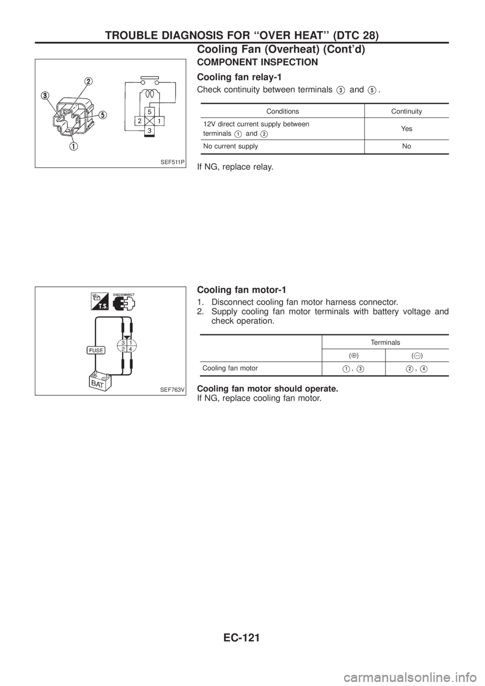
COMPONENT INSPECTION
Cooling fan relay-1
Check continuity between terminalsV3andV5.
Conditions Continuity
12V direct current supply between
terminals
V1andV2Ye s
No current supply No
If NG, replace relay.
Cooling fan motor-1
1. Disconnect cooling fan motor harness connector.
2. Supply cooling fan motor terminals with battery voltage and
check operation.
Terminals
(Å)(@)
Cooling fan motor
V1,V3V2,V4
Cooling fan motor should operate.
If NG, replace cooling fan motor.
SEF511P
SEF763V
TROUBLE DIAGNOSIS FOR ``OVER HEAT'' (DTC 28)
Cooling Fan (Overheat) (Cont'd)
EC-121
Page 281 of 1226
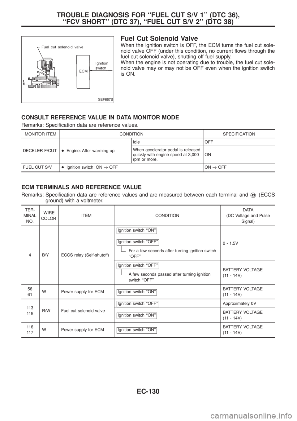
Fuel Cut Solenoid Valve
When the ignition switch is OFF, the ECM turns the fuel cut sole-
noid valve OFF (under this condition, no current ¯ows through the
fuel cut solenoid valve), shutting off fuel supply.
When the engine is not operating due to trouble, the fuel cut sole-
noid valve may or may not be OFF even when the ignition switch
is ON.
CONSULT REFERENCE VALUE IN DATA MONITOR MODE
Remarks: Speci®cation data are reference values.
MONITOR ITEM CONDITION SPECIFICATION
DECELER F/CUT+Engine: After warming upIdle OFF
When accelerator pedal is released
quickly with engine speed at 3,000
rpm or more.ON
FUEL CUT S/V+Ignition switch: ON®OFF ON®OFF
ECM TERMINALS AND REFERENCE VALUE
Remarks: Speci®cation data are reference values and are measured between each terminal andV43(ECCS
ground) with a voltmeter.
TER-
MINAL
NO.WIRE
COLORITEM CONDITIONDATA
(DC Voltage and Pulse
Signal)
4 B/Y ECCS relay (Self-shutoff)Ignition switch ``ON''
Ignition switch ``OFF''
For a few seconds after turning ignition switch
``OFF''0 - 1.5V
Ignition switch ``OFF''
A few seconds passed after turning ignition
switch ``OFF''BATTERY VOLTAGE
(11 - 14V)
56
61W Power supply for ECM Ignition switch ``ON''
BATTERY VOLTAGE
(11 - 14V)
11 3
11 5R/W Fuel cut solenoid valveIgnition switch ``OFF''
Approximately 0V
Ignition switch ``ON''
BATTERY VOLTAGE
(11 - 14V)
11 6
11 7W Power supply for ECM Ignition switch ``ON''
BATTERY VOLTAGE
(11 - 14V)
SEF667S
TROUBLE DIAGNOSIS FOR ``FUEL CUT S/V 1'' (DTC 36),
``FCV SHORT'' (DTC 37), ``FUEL CUT S/V 2'' (DTC 38)
EC-130