2006 NISSAN PATROL torque
[x] Cancel search: torquePage 952 of 1226
M
M/T major overhaul ..........................................MT-9
M/T removal and installation ............................MT-5
MAFS - Wiring diagram..................................EC-73
MAIN - Wiring diagram...................................EC-62
METER - Wiring diagram..............................EL-104
MIL & Data link connectors circuit ...............EC-187
MIL/DL - Wiring diagram ..............................EC-187
MIRROR - Wiring diagram............................EL-188
Main drive gear (M/T).....................................MT-10
Main gear (Transfer) .......................................TF-11
Mainshaft (M/T) ..............................................MT-10
Mainshaft (Transfer) ........................................TF-11
Maintenance (engine) ....................................MA-12
Major overhaul (Transfer) ...............................TF-10
Malfunction indicator lamp (MIL) ....................EC-31
Manifold tightening torque (intake &
exhaust)......................................................MA-12
Manual lock free running hub .........................FA-11
Manual transmission number ..........................GI-37
Mass air ¯ow sensor (MAFS).........................EC-73
Master cylinder (brake) ..................................BR-12
Meter .............................................................EL-102
Mirror, door......................................................BT-46
Mirror, outside .................................................BT-46
Mode door control linkage adjustment ...........HA-77
Model variation ................................................GI-35
Molding - See Exterior ....................................BT-26
Multiport fuel injection precautions ....................GI-3
N
NATS (Nissan Anti-theft System)..................EL-240
NATS - Wiring diagram .................................EL-241
NLS - Wiring diagram...................................EC-125
NVH Troubleshooting (PD)...............................PD-4
NVH troubleshooting (BR)................................BR-2
NVH troubleshooting (EM) ...............................EM-6
NVH troubleshooting (FA) .................................FA-3
NVH troubleshooting (MT) ...............................MT-3
NVH troubleshooting (RA)................................RA-3
NVH troubleshooting (RA)................................RA-3
NVH troubleshooting (ST).................................ST-3
NVH troubleshooting (Transfer) ........................TF-3
NVH troubleshooting CL ...................................CL-3
Needle lift sensor .........................................EC-125
Neutral position switch (M/T) ...........................MT-4
Neutral position switch .................................EC-169
O
Oil change (capacity) .......................................MA-9
Oil cooler (engine) ............................................LC-7
Oil jet.................................................................LC-7
Oil pan (engine) .............................................EM-13Oil pressure (engine) ........................................LC-3
Oil pump (engine) .............................................LC-4
Oil seal replacement (engine)........................EM-20
Oil seal replacement (front ®nal drive
4WD)...........................................................PD-10
Oil seal replacement (front of ®nal
drive) ...........................................................PD-10
Operating cylinder (clutch)................................CL-8
Outside mirror .................................................BT-46
P
P/ANT - Wiring diagram................................EL-181
PCV (positive crankcase ventilation) .............EC-21
PNP/SW - Wiring diagram ...........................EC-169
POWER - Wiring diagram.................................EL-6
Park/Neutral position switch .........................EC-169
Periodic maintenance (for Europe) ..................MA-4
Pinion bearing preload diff. ............................PD-27
Pinion gear height diff. ...................................PD-27
Piston assembly .............................................EM-46
Piston pin inspection ......................................EM-46
Piston ring inspection.....................................EM-47
Piston to bore clearance ................................EM-48
Power antenna ..............................................EL-181
Power door lock ............................................EL-204
Power door lock ............................................EL-211
Power door mirror .........................................EL-188
Power seat ....................................................EL-190
Power steering ¯uid level..................................ST-5
Power steering gear........................................ST-12
Power steering hydraulic pressure ...................ST-6
Power steering oil pump .................................ST-15
Power steering system bleeding.......................ST-6
Power supply routing ........................................EL-5
Power window ...............................................EL-196
Pre-delivery inspection.....................................MA-2
Precautions (General) .......................................GI-2
Pressure plate - See Clutch cover .................CL-14
Priming pump .................................................EC-46
Propeller shaft greasing .................................MA-21
Propeller shaft inspection ..............................MA-21
Propeller shaft on vehicle service ....................PD-6
Propeller shaft vibration ...................................PD-6
Propeller shaft ..................................................PD-5
Q
Quick-glow system check.............................EC-153
Quick-glow system .......................................EC-150
R
R/FOG - Wiring diagram .................................EL-80
R/HEAT - Wiring diagram ...............................HA-14
ALPHABETICAL INDEX
IDX-5
Page 970 of 1226
Cooling Fan (Crankshaft driven)
DISASSEMBLY AND INSTALLATION
+Do not release the drive belt tension by removing the fan/water
pump pulley.
+Fan coupling cannot be disassembled and should be replaced
as a unit. If front markj
Fis present, install fan so that side
markedj
Ffaces the front.
+Install the drive belt only after the fan and fan coupling to water
pump ¯ange bolts/nuts have been properly torqued.
+Proper alignment of these components is essential. Improper
alignment will cause them to wobble and may eventually cause
the fan to separate from the water pump causing extensive
damage.
INSPECTION
Check fan coupling for damage, oil leakage and bent bimetal.
Cooling Fan (Motor driven)
Cooling fan is controlled by ECM. For details, refer to ``Cooling
Fan'', ``TROUBLE DIAGNOSIS FOR DTC 28'' in EC section.
SLC176B
SLC072
SLC177B
ENGINE COOLING SYSTEM
LC-15
Page 977 of 1226
MAINTENANCE
SECTION
MA
CONTENTS
PRECAUTIONS AND PREPARATION............................1
Supplemental Restraint System (SRS) ``AIR
BAG'' and ``SEAT BELT PRE-TENSIONER''...............1
Special Service Tools ..................................................1
PRE-DELIVERY INSPECTION ITEMS............................2
GENERAL MAINTENANCE............................................3
PERIODIC MAINTENANCE............................................4
Engine Oil & Minor Service .........................................4
Engine and Emission Control Service .........................5
Chassis and Body Services.........................................6
Maintenance Under Severe Driving Conditions ..........8
RECOMMENDED FLUIDS AND LUBRICANTS.............9
Fluids and Lubricants ..................................................9
SAE Viscosity Number ..............................................10
Anti-freeze Coolant Mixture Ratio ............................. 11
ENGINE MAINTENANCE..............................................12
Checking Tightening Torque ......................................12
Checking Drive Belt ...................................................12
Changing Engine Oil..................................................13
Changing Engine Oil Filter ........................................14
Changing Engine Coolant..........................................14
Checking Cooling System .........................................16
Checking and Replacing Fuel Filter and Draining
Water .........................................................................16
Checking Fuel Lines ..................................................17
Cleaning and Replacing Air Cleaner Filter ................18
Checking Injection Nozzle .........................................18
Checking Idle Speed .................................................19
Timing Belt Replacement...........................................19
CHASSIS AND BODY MAINTENANCE.......................20
Checking Exhaust System.........................................20
Checking Clutch Fluid Level and Leaks ....................20
Checking Clutch System ...........................................20Checking M/T Oil Level and Leaks ...........................20
Changing M/T Oil.......................................................20
Checking Water Entry ................................................21
Checking Transfer Fluid Level ...................................21
Changing Transfer Fluid ............................................21
Checking Propeller Shaft ...........................................21
Greasing Nipples of Propeller Shafts ........................21
Checking Differential Gear Oil ...................................22
Changing Differential Gear Oil ..................................22
Checking Front Wheel Bearing Grease ....................22
Repacking Front Wheel Bearing and Axle Joint
Grease .......................................................................23
Checking Free-running Hub Grease .........................23
Checking Water Entry in Knuckle Flange..................23
Checking Brake Fluid Level and Leaks.....................23
Checking Brake System ............................................24
Changing Brake Fluid ................................................24
Checking Brake Booster, Vacuum Hoses,
Connections and Check Valve ..................................24
Checking Disc Brake .................................................24
Balancing Wheels ......................................................25
Tire Rotation ..............................................................25
Checking Power Steering Fluid and Lines ................26
Checking Steering Damper .......................................26
Checking Steering Gear Box and Linkage ................26
Lubricating Locks, Hinges and Hood Latches...........27
Checking Seat Belts, Buckles, Retractors,
Anchors and Adjusters...............................................27
Checking Body Corrosion ..........................................28
SERVICE DATA AND SPECIFICATIONS (SDS)..........29
Engine Maintenance ..................................................29
Chassis and Body Maintenance ................................29
MA
Page 989 of 1226
Checking Tightening Torque
Checking should be performed while engine is cold.
MANIFOLD BOLTS AND NUTS
Intake and exhaust manifolds:
M10
:25-29Nzm (2.6 - 3.0 kg-m, 19 - 22 ft-lb)
M8
:16-20Nzm (1.6 - 2.0 kg-m, 12 - 14 ft-lb)
Nut
:16-20Nzm (1.6 - 2.0 kg-m, 12 - 14 ft-lb)
Checking Drive Belt
SMA997C
ENGINE MAINTENANCE
MA-12
Page 998 of 1226
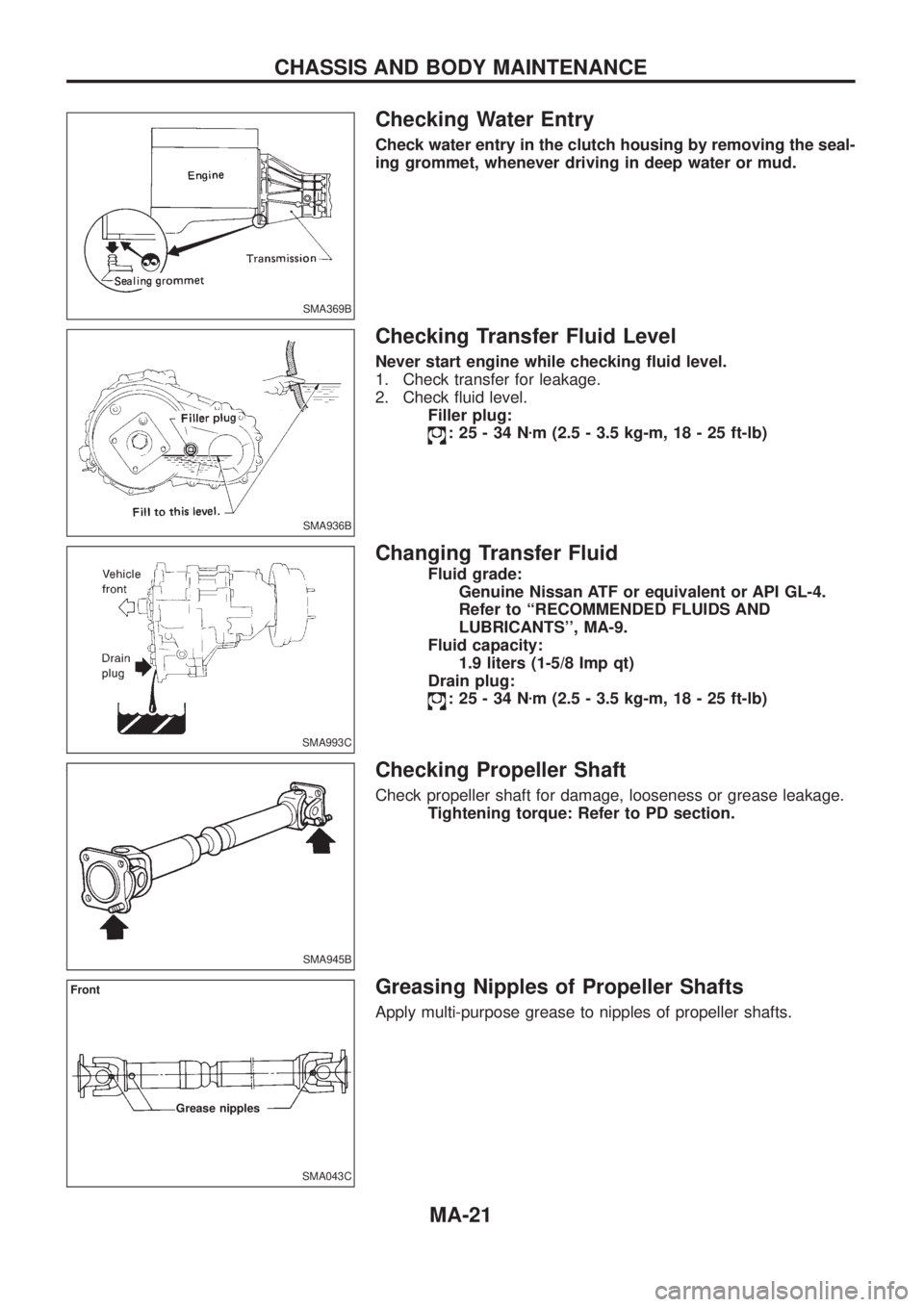
Checking Water Entry
Check water entry in the clutch housing by removing the seal-
ing grommet, whenever driving in deep water or mud.
Checking Transfer Fluid Level
Never start engine while checking ¯uid level.
1. Check transfer for leakage.
2. Check ¯uid level.
Filler plug:
:25-34Nzm (2.5 - 3.5 kg-m, 18 - 25 ft-lb)
Changing Transfer Fluid
Fluid grade:
Genuine Nissan ATF or equivalent or API GL-4.
Refer to ``RECOMMENDED FLUIDS AND
LUBRICANTS'', MA-9.
Fluid capacity:
1.9 liters (1-5/8 Imp qt)
Drain plug:
:25-34Nzm (2.5 - 3.5 kg-m, 18 - 25 ft-lb)
Checking Propeller Shaft
Check propeller shaft for damage, looseness or grease leakage.
Tightening torque: Refer to PD section.
Greasing Nipples of Propeller Shafts
Apply multi-purpose grease to nipples of propeller shafts.
SMA369B
SMA936B
SMA993C
SMA945B
SMA043C
Front
Grease nipples
CHASSIS AND BODY MAINTENANCE
MA-21
Page 1000 of 1226
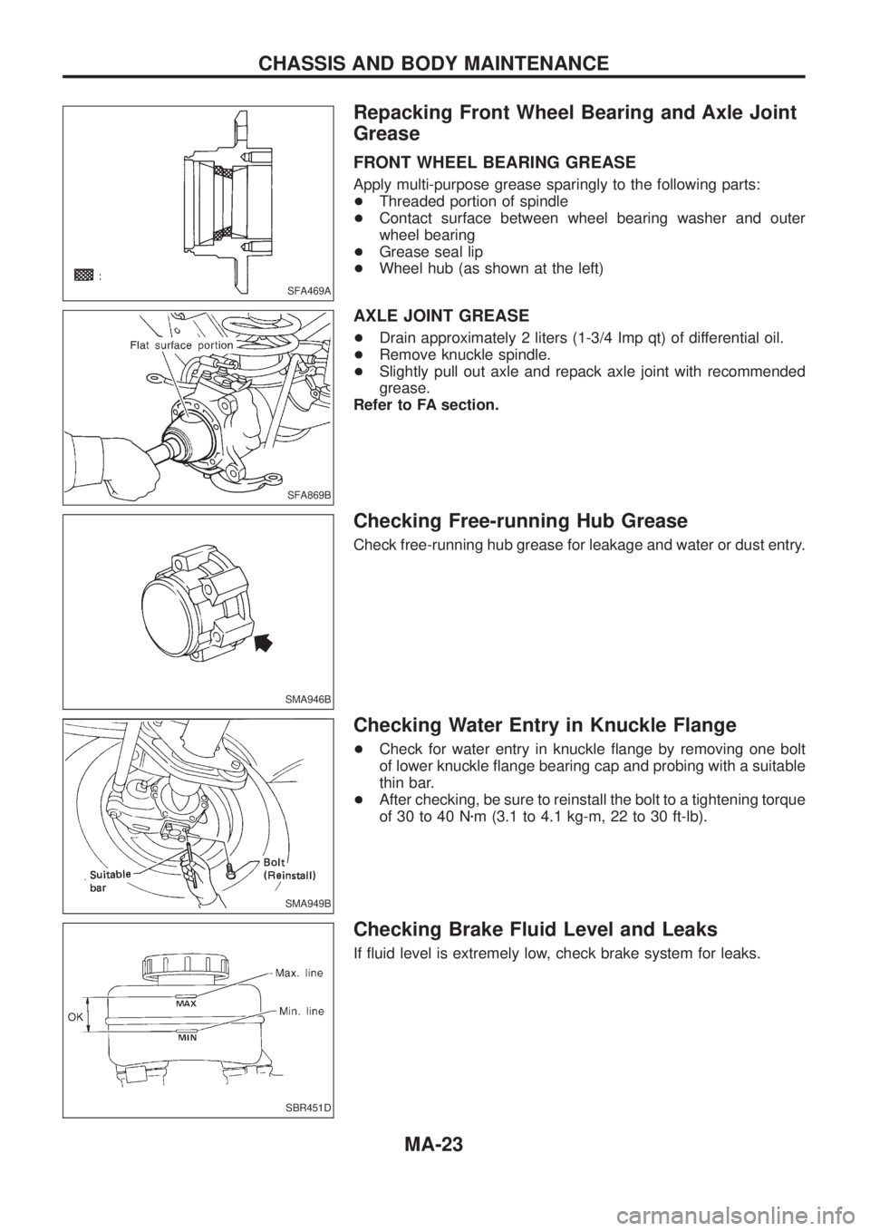
Repacking Front Wheel Bearing and Axle Joint
Grease
FRONT WHEEL BEARING GREASE
Apply multi-purpose grease sparingly to the following parts:
+Threaded portion of spindle
+Contact surface between wheel bearing washer and outer
wheel bearing
+Grease seal lip
+Wheel hub (as shown at the left)
AXLE JOINT GREASE
+Drain approximately 2 liters (1-3/4 Imp qt) of differential oil.
+Remove knuckle spindle.
+Slightly pull out axle and repack axle joint with recommended
grease.
Refer to FA section.
Checking Free-running Hub Grease
Check free-running hub grease for leakage and water or dust entry.
Checking Water Entry in Knuckle Flange
+Check for water entry in knuckle ¯ange by removing one bolt
of lower knuckle ¯ange bearing cap and probing with a suitable
thin bar.
+After checking, be sure to reinstall the bolt to a tightening torque
of 30 to 40 Nzm (3.1 to 4.1 kg-m, 22 to 30 ft-lb).
Checking Brake Fluid Level and Leaks
If ¯uid level is extremely low, check brake system for leaks.
SFA469A
SFA869B
SMA946B
SMA949B
SBR451D
CHASSIS AND BODY MAINTENANCE
MA-23
Page 1013 of 1226
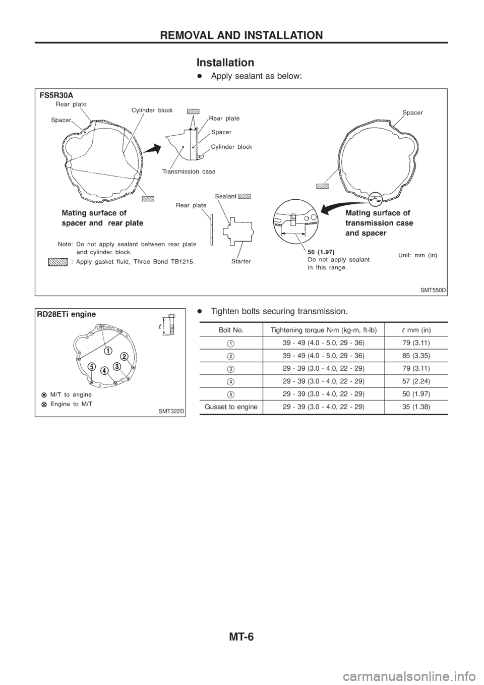
Installation
+Apply sealant as below:
+Tighten bolts securing transmission.
Bolt No. Tightening torque Nzm (kg-m, ft-lb)!mm (in)
V139 - 49 (4.0 - 5.0, 29 - 36) 79 (3.11)
V239 - 49 (4.0 - 5.0, 29 - 36) 85 (3.35)
V329 - 39 (3.0 - 4.0, 22 - 29) 79 (3.11)
V429 - 39 (3.0 - 4.0, 22 - 29) 57 (2.24)
V529 - 39 (3.0 - 4.0, 22 - 29) 50 (1.97)
Gusset to engine 29 - 39 (3.0 - 4.0, 22 - 29) 35 (1.38)
SMT550D
SMT322D
REMOVAL AND INSTALLATION
MT-6
Page 1044 of 1226
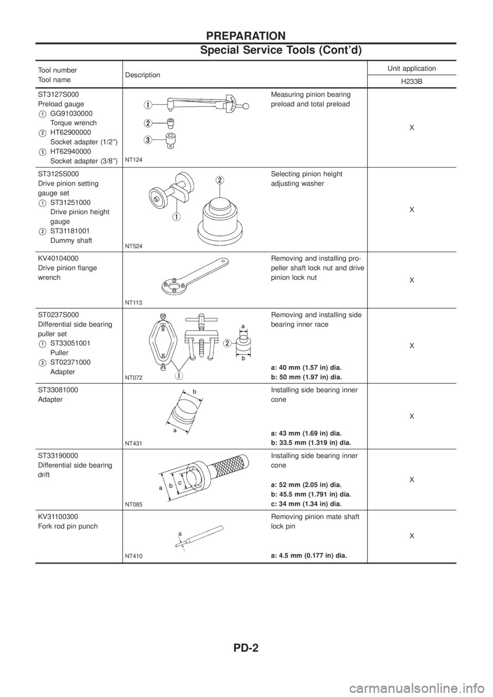
Tool number
Tool nameDescriptionUnit application
H233B
ST3127S000
Preload gauge
V1GG91030000
Torque wrench
V2HT62900000
Socket adapter (1/2²)
V3HT62940000
Socket adapter (3/8²)NT124
Measuring pinion bearing
preload and total preload
X
ST3125S000
Drive pinion setting
gauge set
V1ST31251000
Drive pinion height
gauge
V2ST31181001
Dummy shaft
NT524
Selecting pinion height
adjusting washer
X
KV40104000
Drive pinion ¯ange
wrench
NT113
Removing and installing pro-
peller shaft lock nut and drive
pinion lock nut
X
ST0237S000
Differential side bearing
puller set
V1ST33051001
Puller
V2ST02371000
Adapter
NT072
Removing and installing side
bearing inner race
X
a: 40 mm (1.57 in) dia.
b: 50 mm (1.97 in) dia.
ST33081000
Adapter
NT431
Installing side bearing inner
cone
X
a: 43 mm (1.69 in) dia.
b: 33.5 mm (1.319 in) dia.
ST33190000
Differential side bearing
drift
NT085
Installing side bearing inner
cone
X
a: 52 mm (2.05 in) dia.
b: 45.5 mm (1.791 in) dia.
c: 34 mm (1.34 in) dia.
KV31100300
Fork rod pin punch
NT410
Removing pinion mate shaft
lock pin
X
a: 4.5 mm (0.177 in) dia.
PREPARATION
Special Service Tools (Cont'd)
PD-2