Page 135 of 1226
Commercial Service Tools
Tool name Description
V1Flare nut crowfoot
V2Torque wrench
NT684
Removing and installing clutch piping
a: 10 mm (0.39 in)
Bearing puller
NT077
Removing release bearing
Wire
NT727
Installing clutch cover
Wire: 3.2 mm (0.126 in) dia.
Bearing drift
NT474
Installing release bearing
a: 52 mm (2.05 in) dia.
b: 45 mm (1.77 in) dia.
PRECAUTIONS AND PREPARATION
CL-2
Page 306 of 1226

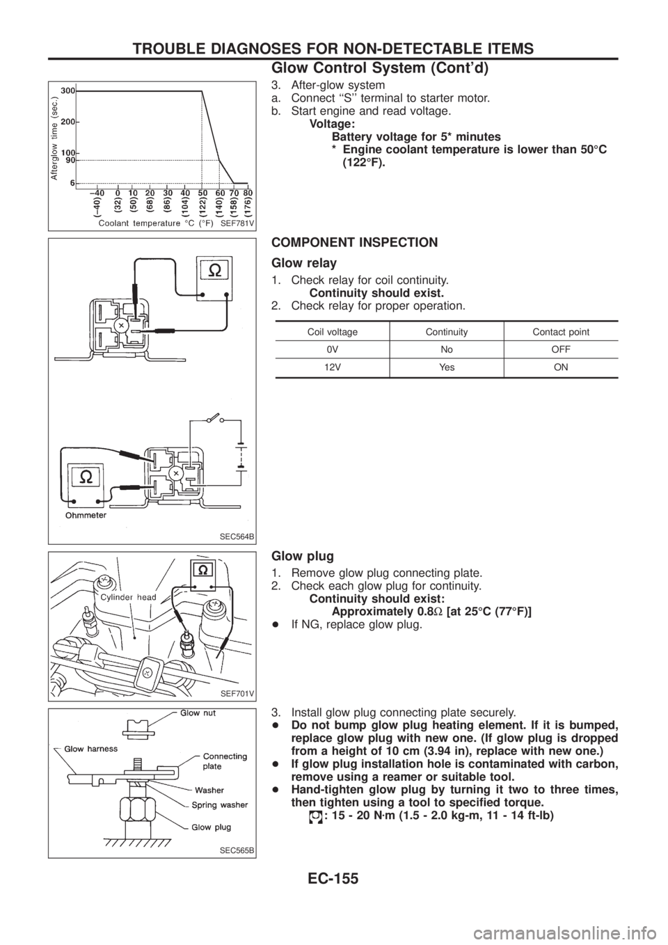
3. After-glow system
a. Connect ``S'' terminal to starter motor.
b. Start engine and read voltage.
Voltage:
Battery voltage for 5* minutes
* Engine coolant temperature is lower than 50ÉC
(122ÉF).
COMPONENT INSPECTION
Glow relay
1. Check relay for coil continuity.
Continuity should exist.
2. Check relay for proper operation.
Coil voltage Continuity Contact point
0V No OFF
12V Yes ON
Glow plug
1. Remove glow plug connecting plate.
2. Check each glow plug for continuity.
Continuity should exist:
Approximately 0.8W[at 25ÉC (77ÉF)]
+If NG, replace glow plug.
3. Install glow plug connecting plate securely.
+Do not bump glow plug heating element. If it is bumped,
replace glow plug with new one. (If glow plug is dropped
from a height of 10 cm (3.94 in), replace with new one.)
+If glow plug installation hole is contaminated with carbon,
remove using a reamer or suitable tool.
+Hand-tighten glow plug by turning it two to three times,
then tighten using a tool to speci®ed torque.
:15-20Nzm (1.5 - 2.0 kg-m, 11 - 14 ft-lb)
SEF781V
SEC564B
SEF701V
SEC565B
TROUBLE DIAGNOSES FOR NON-DETECTABLE ITEMS
Glow Control System (Cont'd)
EC-155
Page 398 of 1226

Trouble Diagnoses
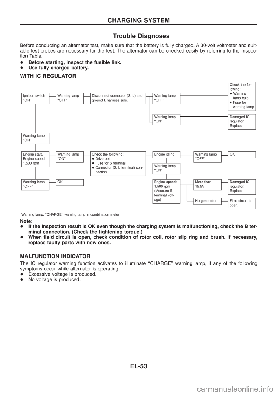
Before conducting an alternator test, make sure that the battery is fully charged. A 30-volt voltmeter and suit-
able test probes are necessary for the test. The alternator can be checked easily by referring to the Inspec-
tion Table.
+Before starting, inspect the fusible link.
+Use fully charged battery.
WITH IC REGULATOR
Check the fol-
lowing:
+Warning
lamp bulb
+Fuse for
warning lamp
Ignition switch
``ON''Warning lamp
``OFF''Disconnect connector (S, L) and
ground L harness side.Warning lamp
``OFF''
Warning lamp
``ON''Damaged IC
regulator.
Replace.
Warning lamp
``ON''
Engine start.
Engine speed:
1,500 rpmWarning lamp
``ON''Check the following:
+Drive belt
+Fuse for S terminal
+Connector (S, L terminal) con-
nectionEngine idlingWarning lamp
``OFF''OK
Warning lamp
``ON''
Warning lamp
``OFF''OKEngine speed:
1,500 rpm
(Measure B
terminal volt-
age)More than
15.5VDamaged IC
regulator.
Replace.
No generationField circuit is
open.
Warning lamp: ``CHARGE'' warning lamp in combination meter
Note:
+If the inspection result is OK even though the charging system is malfunctioning, check the B ter-
minal connection. (Check the tightening torque.)
+When ®eld circuit is open, check condition of rotor coil, rotor slip ring and brush. If necessary,
replace faulty parts with new ones.
MALFUNCTION INDICATOR
The IC regulator warning function activates to illuminate ``CHARGE'' warning lamp, if any of the following
symptoms occur while alternator is operating:
+Excessive voltage is produced.
+No voltage is produced.
CHARGING SYSTEM
EL-53
Page 488 of 1226
Removal and Installation
WIPER ARMS
1. Prior to wiper arm installation, turn on wiper switch to operate
wiper motor and then turn it ``OFF'' (Auto Stop).
2. Lift the blade up and then set it down onto glass surface to set
the blade center to clearance ``L
1''&``L2'' immediately before
tightening nut.
3. Eject washer ¯uid. Turn on wiper switch to operate wiper motor
and then turn it ``OFF''.
4. Ensure that wiper blades stop within clearance ``L
1''&``L2''.
Clearance ``L
1'': 25 mm (0.98 in)
Clearance ``L
2'': 23 mm (0.91 in)
+Tighten wiper arm nuts to speci®ed torque.
Front wiper: 21 - 26 Nzm (2.1 - 2.7 kg-m, 15 - 20 ft-lb)
+Before reinstalling wiper arm, clean up the pivot area as
illustrated. This will reduce possibility of wiper arm loose-
ness.
WIPER LINKAGE
SEL543TA
SEL024J
CEL741
FRONT WIPER AND WASHER
EL-143
Page 496 of 1226
Removal and Installation
WIPER ARM
1. Prior to wiper arm installation, turn on wiper switch to operate
wiper motor and then turn it ``OFF'' (Auto Stop).
2. Lift the blade up and then set it down onto glass surface. Set
the blade center to clearance ``E'' immediately before tighten-
ing nut.
3. Eject washer ¯uid. Turn on wiper switch to operate wiper motor
and then turn it ``OFF''.
4. Ensure that wiper blades stop within clearance ``E''.
Clearance ``E'': 20 mm (0.79 in)
+Tighten windshield wiper arm nuts to speci®ed torque.
:13-18Nzm (1.3 - 1.8 kg-m,9-13ft-lb)
+Before reinstalling wiper arm, clean up the pivot area as
illustrated. This will reduce possibility of wiper arm loose-
ness.
Washer Nozzle Adjustment
+Adjust washer nozzle with suitable tool as shown in the ®gure
at left.
Adjustable range: 10É (In any direction)
Unit: mm (in)
*1 30 (1.18) *3 40 (1.57)
*2 30 (1.18) *4 20 (0.79)
CEL779
SEL024J
SEL241P
CEL780
REAR WIPER AND WASHER
EL-151
Page 499 of 1226

Electrical Components Inspection
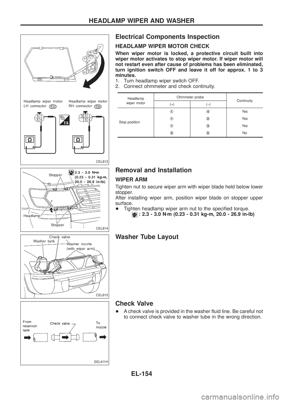
HEADLAMP WIPER MOTOR CHECK
When wiper motor is locked, a protective circuit built into
wiper motor activates to stop wiper motor. If wiper motor will
not restart even after cause of problems has been eliminated,
turn ignition switch OFF and leave it off for approx. 1 to 3
minutes.
1. Turn headlamp wiper switch OFF.
2. Connect ohmmeter and check continuity.
Headlamp
wiper motorOhmmeter probe
Continuity
(+) (þ)
Stop positionj
1j4Ye s
j
1j2Ye s
j
1j3Ye s
j
3j5No
Removal and Installation
WIPER ARM
Tighten nut to secure wiper arm with wiper blade held below lower
stopper.
After installing wiper arm, position wiper blade on stopper upper
surface.
+Tighten headlamp wiper arm nut to the speci®ed torque.
: 2.3 - 3.0 Nzm (0.23 - 0.31 kg-m, 20.0 - 26.9 in-lb)
Washer Tube Layout
Check Valve
+A check valve is provided in the washer ¯uid line. Be careful not
to connect check valve to washer tube in the wrong direction.
CEL813
CEL814
CEL815
SEL411H
HEADLAMP WIPER AND WASHER
EL-154
Page 662 of 1226
LHD MODELS
Installation
To install SMJ, tighten bolts until orange ``fulltight'' mark appears
and then retighten to speci®ed torque as required.
: 3-5Nzm
(0.3 - 0.5 kg-m, 26 - 43 in-lb)
CAUTION:
Do not overtighten bolts, otherwise, they may be damaged.
RHD MODELS
Installation
To install SMJ, tighten bolts until orange ``fulltight'' mark appears
and then retighten to speci®ed torque as required.
: 3-5Nzm
(0.3 - 0.5 kg-m, 26 - 43 in-lb)
CAUTION:
Do not overtighten bolts, otherwise, they may be damaged.
CEL773
CEL789
CEL841
CEL842
SUPER MULTIPLE JUNCTION (SMJ)
EL-317
Page 669 of 1226

Parts Requiring Angular Tightening
+Some important engine parts are tightened using an angular-
tightening method rather than a torque setting method.
+If these parts are tightened using a torque setting method, dis-
persal of the tightening force (axial bolt force) will be two or
three times that of the dispersal produced by using the correct
angular-tightening method.
+Although the torque setting values (described in this manual)
are equivalent to those used when bolts and nuts are tightened
with an angular-tightening method, they should be used for
reference only.
+To assure the satisfactory maintenance of the engine, bolts and
nuts must be tightened using an angular-tightening method.
+Before tightening the bolts and nuts, ensure that the thread and
seating surfaces are clean and then coated with engine oil.
+The bolts and nuts which require the angular-tightening method
are cylinder head bolts.
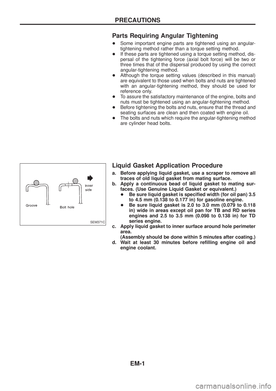
Liquid Gasket Application Procedure
a. Before applying liquid gasket, use a scraper to remove all
traces of old liquid gasket from mating surface.
b. Apply a continuous bead of liquid gasket to mating sur-
faces. (Use Genuine Liquid Gasket or equivalent.)
+Be sure liquid gasket is speci®ed width (for oil pan) 3.5
to 4.5 mm (0.138 to 0.177 in) for gasoline engine.
+Be sure liquid gasket is 2.0 to 3.0 mm (0.079 to 0.118
in) wide in areas except oil pan for TB and RD series
engines and 2.5 to 3.5 mm (0.098 to 0.138 in) for TD
series engine.
c. Apply liquid gasket to inner surface around hole perimeter
area.
(Assembly should be done within 5 minutes after coating.)
d. Wait at least 30 minutes before re®lling engine oil and
engine coolant.
SEM371C
PRECAUTIONS
EM-1