Page 708 of 1226

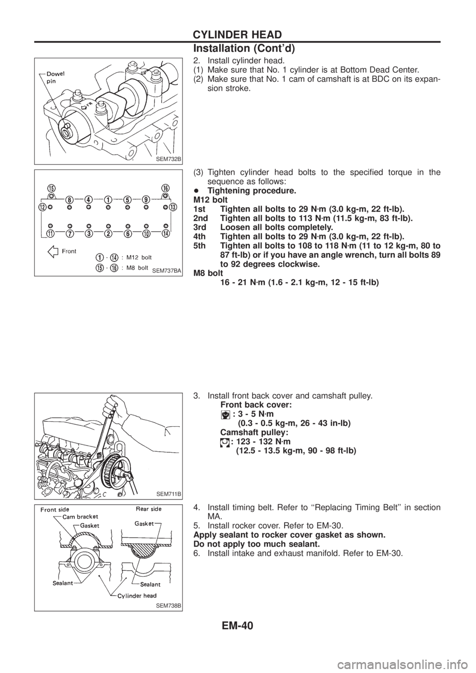
2. Install cylinder head.
(1) Make sure that No. 1 cylinder is at Bottom Dead Center.
(2) Make sure that No. 1 cam of camshaft is at BDC on its expan-
sion stroke.
(3) Tighten cylinder head bolts to the speci®ed torque in the
sequence as follows:
+Tightening procedure.
M12 bolt
1st Tighten all bolts to 29 Nzm (3.0 kg-m, 22 ft-lb).
2nd Tighten all bolts to 113 Nzm (11.5 kg-m, 83 ft-lb).
3rd Loosen all bolts completely.
4th Tighten all bolts to 29 Nzm (3.0 kg-m, 22 ft-lb).
5th Tighten all bolts to 108 to 118 Nzm (11 to 12 kg-m, 80 to
87 ft-lb) or if you have an angle wrench, turn all bolts 89
to 92 degrees clockwise.
M8 bolt
16-21Nzm (1.6 - 2.1 kg-m, 12 - 15 ft-lb)
3. Install front back cover and camshaft pulley.
Front back cover:
:3-5Nzm
(0.3 - 0.5 kg-m, 26 - 43 in-lb)
Camshaft pulley:
: 123 - 132 Nzm
(12.5 - 13.5 kg-m, 90 - 98 ft-lb)
4. Install timing belt. Refer to ``Replacing Timing Belt'' in section
MA.
5. Install rocker cover. Refer to EM-30.
Apply sealant to rocker cover gasket as shown.
Do not apply too much sealant.
6. Install intake and exhaust manifold. Refer to EM-30.
SEM732B
SEM737BA
SEM711B
SEM738B
CYLINDER HEAD
Installation (Cont'd)
EM-40
Page 720 of 1226

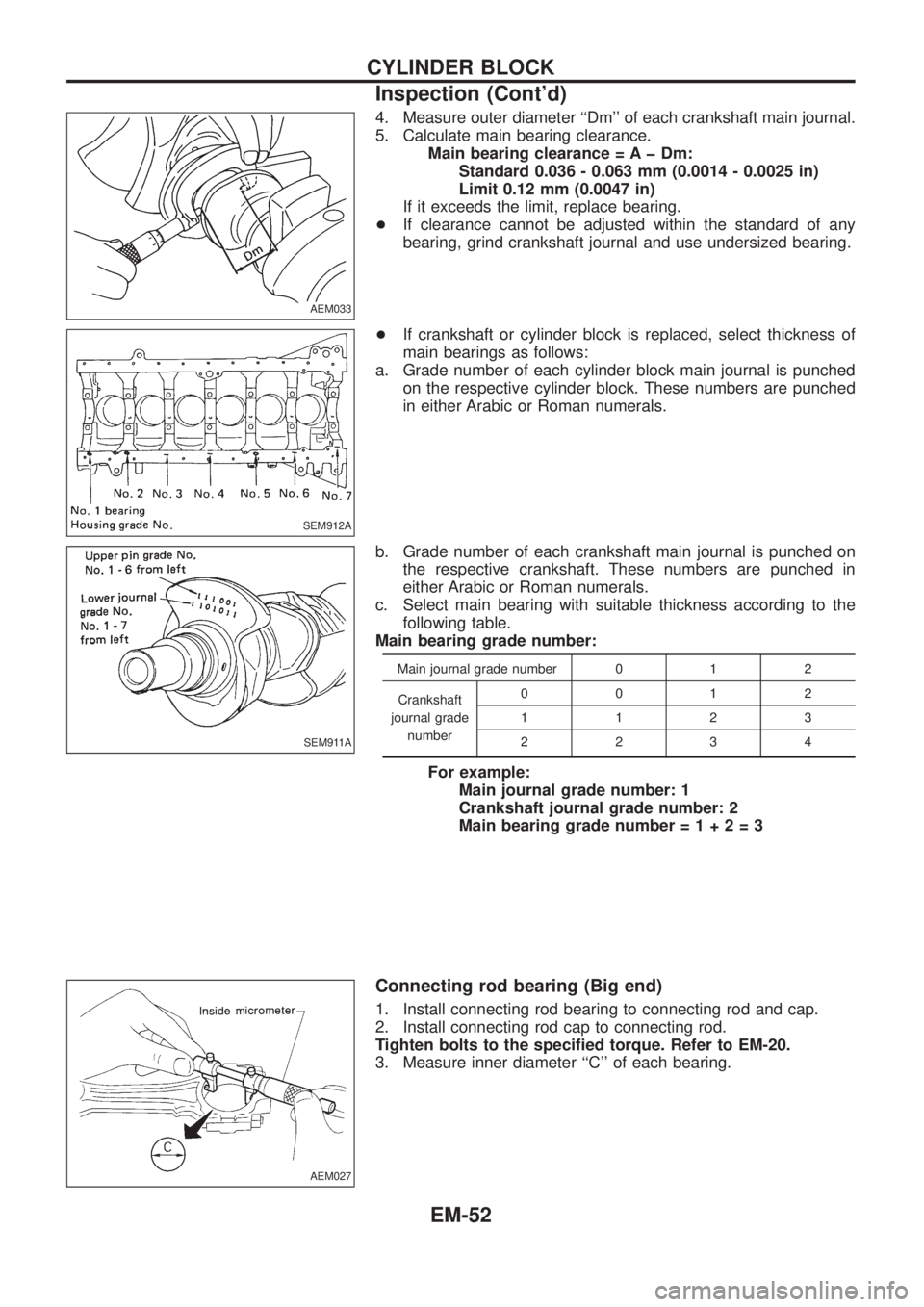
4. Measure outer diameter ``Dm'' of each crankshaft main journal.
5. Calculate main bearing clearance.
Main bearing clearance = A þ Dm:
Standard 0.036 - 0.063 mm (0.0014 - 0.0025 in)
Limit 0.12 mm (0.0047 in)
If it exceeds the limit, replace bearing.
+If clearance cannot be adjusted within the standard of any
bearing, grind crankshaft journal and use undersized bearing.
+If crankshaft or cylinder block is replaced, select thickness of
main bearings as follows:
a. Grade number of each cylinder block main journal is punched
on the respective cylinder block. These numbers are punched
in either Arabic or Roman numerals.
b. Grade number of each crankshaft main journal is punched on
the respective crankshaft. These numbers are punched in
either Arabic or Roman numerals.
c. Select main bearing with suitable thickness according to the
following table.
Main bearing grade number:
Main journal grade number 0 1 2
Crankshaft
journal grade
number0012
1123
2234
For example:
Main journal grade number: 1
Crankshaft journal grade number: 2
Main bearing grade number=1+2=3
Connecting rod bearing (Big end)
1. Install connecting rod bearing to connecting rod and cap.
2. Install connecting rod cap to connecting rod.
Tighten bolts to the speci®ed torque. Refer to EM-20.
3. Measure inner diameter ``C'' of each bearing.
AEM033
SEM912A
SEM911A
AEM027
CYLINDER BLOCK
Inspection (Cont'd)
EM-52
Page 723 of 1226

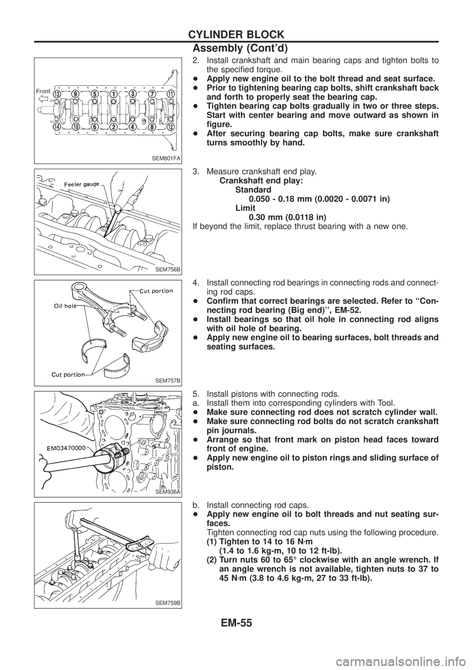
2. Install crankshaft and main bearing caps and tighten bolts to
the speci®ed torque.
+Apply new engine oil to the bolt thread and seat surface.
+Prior to tightening bearing cap bolts, shift crankshaft back
and forth to properly seat the bearing cap.
+Tighten bearing cap bolts gradually in two or three steps.
Start with center bearing and move outward as shown in
®gure.
+After securing bearing cap bolts, make sure crankshaft
turns smoothly by hand.
3. Measure crankshaft end play.
Crankshaft end play:
Standard
0.050 - 0.18 mm (0.0020 - 0.0071 in)
Limit
0.30 mm (0.0118 in)
If beyond the limit, replace thrust bearing with a new one.
4. Install connecting rod bearings in connecting rods and connect-
ing rod caps.
+Con®rm that correct bearings are selected. Refer to ``Con-
necting rod bearing (Big end)'', EM-52.
+Install bearings so that oil hole in connecting rod aligns
with oil hole of bearing.
+Apply new engine oil to bearing surfaces, bolt threads and
seating surfaces.
5. Install pistons with connecting rods.
a. Install them into corresponding cylinders with Tool.
+Make sure connecting rod does not scratch cylinder wall.
+Make sure connecting rod bolts do not scratch crankshaft
pin journals.
+Arrange so that front mark on piston head faces toward
front of engine.
+Apply new engine oil to piston rings and sliding surface of
piston.
b. Install connecting rod caps.
+Apply new engine oil to bolt threads and nut seating sur-
faces.
Tighten connecting rod cap nuts using the following procedure.
(1) Tighten to 14 to 16 Nzm
(1.4 to 1.6 kg-m, 10 to 12 ft-lb).
(2) Turn nuts 60 to 65É clockwise with an angle wrench. If
an angle wrench is not available, tighten nuts to 37 to
45 Nzm (3.8 to 4.6 kg-m, 27 to 33 ft-lb).
SEM801FA
SEM756B
SEM757B
SEM936A
SEM759B
CYLINDER BLOCK
Assembly (Cont'd)
EM-55
Page 734 of 1226
Precautions
+When installing rubber parts, ®nal tightening must be car-
ried out under unladen condition* with tires on ground.
* Fuel, radiator coolant and engine oil full. Spare tire, jack,
hand tools and mats in designated positions.
+Use ¯are nut wrench when removing and installing brake
tubes.
+After installing removed suspension parts, check wheel
alignment and adjust if necessary.
+Always torque brake lines when installing.
Special Service Tools
Tool number
Tool nameDescription
ST29020001
Gear arm puller
NT551
Removing tie-rod and drag link
a: 34 mm (1.34 in)
b: 6.5 mm (0.256 in)
c: 61.5 mm (2.421 in)
KV401021S0
Bearing race drift
NT153
Installing wheel bearing outer race
KV40105400
Wheel bearing
lock nut wrench
NT154
Removing and installing wheel bearing lock
nut
GG94310000
Flare nut torque wrench
NT406
Removing and installing brake piping
a: 10 mm (0.39 in)
SBR820BA
PRECAUTIONS AND PREPARATION
FA-1
Page 735 of 1226
Commercial Service Tools
Tool name Description
Equivalent to GG94310000
V1Flare nut crowfoot
V2Torque wrench
NT360
Removing and installing each brake piping
a: 10 mm (0.39 in)
Hub cap drift
NT115
Installing hub cap
a: 57 mm (2.24 in) dia.
b: 46 mm (1.81 in) dia.
PRECAUTIONS AND PREPARATION
FA-2
Page 738 of 1226
Front Axle and Front Suspension Parts
Check front axle and front suspension parts for excessive play,
cracks, wear and other damage.
+Shake each front wheel to check for excessive play.
+Make sure that cotter pin is inserted.
+Retighten all axle and suspensions nuts and bolts to the speci-
®ed torque.
Tightening torque:
Refer to FRONT SUSPENSION (FA-24).
+Check front axle and front suspension parts for wear, cracks
and other damage.
+Check shock absorber for oil leakage and other damage.
+Check knuckle ¯ange for grease leakage and knuckle ¯ange
grease seal for cracks and other damage.
Front Wheel Bearing
+Check that wheel bearings operate smoothly.
+Check axial end play.
Axial end play:
0mm(0in)
+Adjust wheel bearing preload if there is any axial end play or
wheel bearing does not turn smoothly.
SMA525A
SFA851B
SFA852B
SFA413A
ON-VEHICLE SERVICE
FA-5
Page 739 of 1226
PRELOAD ADJUSTMENT
Adjust wheel bearing preload after wheel bearing has been
replaced or front axle has been reassembled.
Adjust wheel bearing preload as follows:
1. Before adjustment, thoroughly clean all parts to prevent dirt
entry.
2. Apply multi-purpose grease sparingly to the following parts:
+Wheel hub (as shown at left)
+Wheel bearing
+Grease seal lip
+Contact surface between wheel bearing lock washer (cham-
fered side) and outer wheel bearing
3. Tighten wheel bearing lock nut with Tool.
: 167 - 196 Nzm (17 - 20 kg-m, 123 - 145 ft-lb)
4. Turn wheel hub several times in both directions.
5. Loosen wheel bearing lock nut so that torque becomes0Nzm
(0 kg-m, 0 ft-lb).
6. Retighten wheel bearing lock nut with Tool.
:3-5Nzm (0.3 - 0.5 kg-m, 26 - 43 in-lb)
SFA853B
SFA469A
FA781
SFA748BA
ON-VEHICLE SERVICE
Front Wheel Bearing (Cont'd)
FA-6
Page 742 of 1226

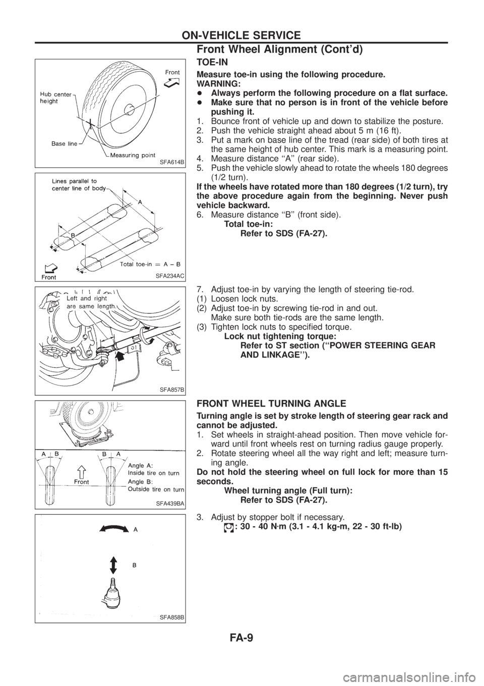
TOE-IN
Measure toe-in using the following procedure.
WARNING:
+Always perform the following procedure on a ¯at surface.
+Make sure that no person is in front of the vehicle before
pushing it.
1. Bounce front of vehicle up and down to stabilize the posture.
2. Push the vehicle straight ahead about 5 m (16 ft).
3. Put a mark on base line of the tread (rear side) of both tires at
the same height of hub center. This mark is a measuring point.
4. Measure distance ``A'' (rear side).
5. Push the vehicle slowly ahead to rotate the wheels 180 degrees
(1/2 turn).
If the wheels have rotated more than 180 degrees (1/2 turn), try
the above procedure again from the beginning. Never push
vehicle backward.
6. Measure distance ``B'' (front side).
Total toe-in:
Refer to SDS (FA-27).
7. Adjust toe-in by varying the length of steering tie-rod.
(1) Loosen lock nuts.
(2) Adjust toe-in by screwing tie-rod in and out.
Make sure both tie-rods are the same length.
(3) Tighten lock nuts to speci®ed torque.
Lock nut tightening torque:
Refer to ST section (``POWER STEERING GEAR
AND LINKAGE'').
FRONT WHEEL TURNING ANGLE
Turning angle is set by stroke length of steering gear rack and
cannot be adjusted.
1. Set wheels in straight-ahead position. Then move vehicle for-
ward until front wheels rest on turning radius gauge properly.
2. Rotate steering wheel all the way right and left; measure turn-
ing angle.
Do not hold the steering wheel on full lock for more than 15
seconds.
Wheel turning angle (Full turn):
Refer to SDS (FA-27).
3. Adjust by stopper bolt if necessary.
:30-40Nzm (3.1 - 4.1 kg-m, 22 - 30 ft-lb)
SFA614B
SFA234AC
SFA857B
SFA439BA
SFA858B
ON-VEHICLE SERVICE
Front Wheel Alignment (Cont'd)
FA-9