2006 NISSAN PATROL tank
[x] Cancel search: tankPage 973 of 1226
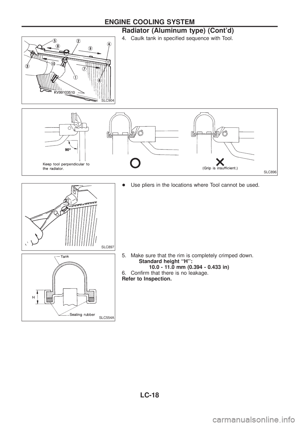
4. Caulk tank in speci®ed sequence with Tool.
+Use pliers in the locations where Tool cannot be used.
5. Make sure that the rim is completely crimped down.
Standard height ``H'':
10.0 - 11.0 mm (0.394 - 0.433 in)
6. Con®rm that there is no leakage.
Refer to Inspection.
SLC904
SLC896
SLC897
SLC554A
ENGINE COOLING SYSTEM
Radiator (Aluminum type) (Cont'd)
LC-18
Page 975 of 1226
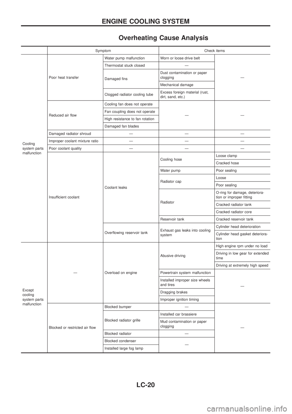
Overheating Cause Analysis
Symptom Check items
Cooling
system parts
malfunctionPoor heat transferWater pump malfunction Worn or loose drive belt
Ð Thermostat stuck closed Ð
Damaged ®nsDust contamination or paper
clogging
Mechanical damage
Clogged radiator cooling tubeExcess foreign material (rust,
dirt, sand, etc.)
Reduced air ¯owCooling fan does not operate
ÐÐ Fan coupling does not operate
High resistance to fan rotation
Damaged fan blades
Damaged radiator shroud Ð Ð Ð
Improper coolant mixture ratio Ð Ð Ð
Poor coolant quality Ð Ð Ð
Insufficient coolantCoolant leaksCooling hoseLoose clamp
Cracked hose
Water pump Poor sealing
Radiator capLoose
Poor sealing
RadiatorO-ring for damage, deteriora-
tion or improper ®tting
Cracked radiator tank
Cracked radiator core
Reservoir tank Cracked reservoir tank
Over¯owing reservoir tankExhaust gas leaks into cooling
systemCylinder head deterioration
Cylinder head gasket deteriora-
tion
Except
cooling
system parts
malfunctionÐ Overload on engineAbusive drivingHigh engine rpm under no load
Driving in low gear for extended
time
Driving at extremely high speed
Powertrain system malfunction
Ð Installed improper size wheels
and tires
Dragging brakes
Improper ignition timing
Blocked or restricted air ¯owBlocked bumper Ð
Ð Blocked radiator grilleInstalled car brassiere
Mud contamination or paper
clogging
Blocked radiator Ð
Blocked condenser
Ð
Installed large fog lamp
ENGINE COOLING SYSTEM
LC-20
Page 980 of 1226
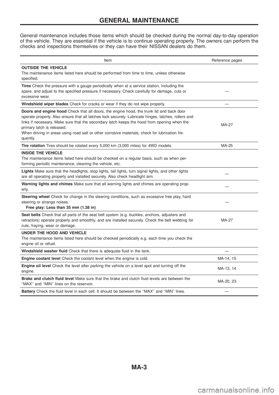
General maintenance includes those items which should be checked during the normal day-to-day operation
of the vehicle. They are essential if the vehicle is to continue operating properly. The owners can perform the
checks and inspections themselves or they can have their NISSAN dealers do them.
Item Reference pages
OUTSIDE THE VEHICLE
The maintenance items listed here should be performed from time to time, unless otherwise
speci®ed.
TiresCheck the pressure with a gauge periodically when at a service station, including the
spare, and adjust to the speci®ed pressure if necessary. Check carefully for damage, cuts or
excessive wear.Ð
Windshield wiper bladesCheck for cracks or wear if they do not wipe properly. Ð
Doors and engine hoodCheck that all doors, the engine hood, the trunk lid and back door
operate properly. Also ensure that all latches lock securely. Lubricate hinges, latches, rollers and
links if necessary. Make sure that the secondary latch keeps the hood from opening when the
primary latch is released.
When driving in areas using road salt or other corrosive materials, check for lubrication fre-
quently.MA-27
Tire rotationTires should be rotated every 5,000 km (3,000 miles) for 4WD models. MA-25
INSIDE THE VEHICLE
The maintenance items listed here should be checked on a regular basis, such as when per-
forming periodic maintenance, cleaning the vehicle, etc.
LightsMake sure that the headlights, stop lights, tail lights, turn signal lights, and other lights
are all operating properly and installed securely. Also check headlight aim.Ð
Warning lights and chimesMake sure that all warning lights and chimes are operating prop-
erly.Ð
Steering wheelCheck for change in the steering conditions, such as excessive free play, hard
steering or strange noises.
Free play: Less than 35 mm (1.38 in)Ð
Seat beltsCheck that all parts of the seat belt system (e.g. buckles, anchors, adjusters and
retractors) operate properly and smoothly, and are installed securely. Check the belt webbing for
cuts, fraying, wear or damage.MA-27
UNDER THE HOOD AND VEHICLE
The maintenance items listed here should be checked periodically e.g. each time you check the
engine oil or refuel.
Windshield washer ¯uidCheck that there is adequate ¯uid in the tank. Ð
Engine coolant levelCheck the coolant level when the engine is cold. MA-14, 15
Engine oil levelCheck the level after parking the vehicle on a level spot and turning off the
engine.MA-13, 14
Brake and clutch ¯uid levelMake sure that the brake and clutch ¯uid levels are between the
``MAX'' and ``MIN'' lines on the reservoir.MA-20, 23
BatteryCheck the ¯uid level in each cell. It should be between the ``MAX'' and ``MIN'' lines. Ð
GENERAL MAINTENANCE
MA-3
Page 986 of 1226
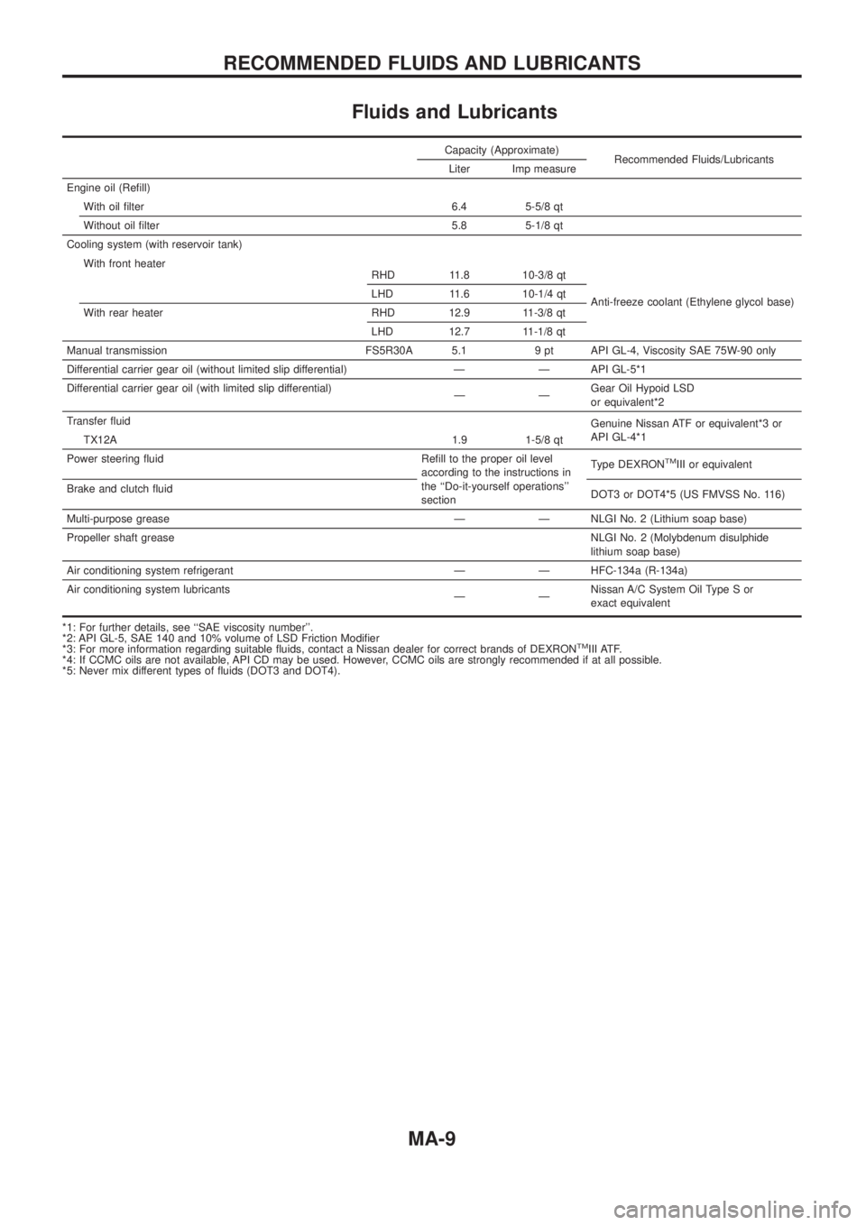
Fluids and Lubricants
Capacity (Approximate)Recommended Fluids/Lubricants
Liter Imp measure
Engine oil (Re®ll) With oil ®lter 6.4 5-5/8 qt
Without oil ®lter 5.8 5-1/8 qt
Cooling system (with reservoir tank)
Anti-freeze coolant (Ethylene glycol base)
With front heater
RHD 11.8 10-3/8 qt
LHD 11.6 10-1/4 qt
With rear heater RHD 12.9 11-3/8 qt LHD 12.7 11-1/8 qt
Manual transmission FS5R30A 5.1 9 pt API GL-4, Viscosity SAE 75W-90 only
Differential carrier gear oil (without limited slip differential) Ð Ð API GL-5*1
Differential carrier gear oil (with limited slip differential) ÐÐGearOilHypoidLSD
orequivalent*2
Transfer ¯uid Genuine Nissan ATF or equivalent*3 or
API GL-4*1
TX12A 1.9 1-5/8 qt
Power steering ¯uid Re®ll to the proper oil level according to the instructions in
the ``Do-it-yourself operations''
sectionType DEXRON
TMIII or equivalent
Brake and clutch ¯uid DOT3 or DOT4*5 (US FMVSS No. 116)
Multi-purpose grease Ð Ð NLGI No. 2 (Lithium soap base)
Propeller shaft grease NLGI No. 2 (Molybdenum disulphide
lithium soap base)
Air conditioning system refrigerant Ð Ð HFC-134a (R-134a)
Air conditioning system lubricants ÐÐNissan A/C System Oil Type S or
exact equivalent
*1: For further details, see ``SAE viscosity number''.
*2:APIGL-5,SAE140and10%volumeofLSDFrictionModi®er
*3: For more information regarding suitable ¯uids, contact a Nissan dealer for correct brands of DEXRON
TMIII ATF.
*4: If CCMC oils are not available, API CD may be used. However, CCMC oils are strongly recommended if at all possible.
*5: Never mix different types of ¯uids (DOT3 and DOT4).
RECOMMENDED FLUIDS AND LUBRICANTS
MA-9
Page 991 of 1226
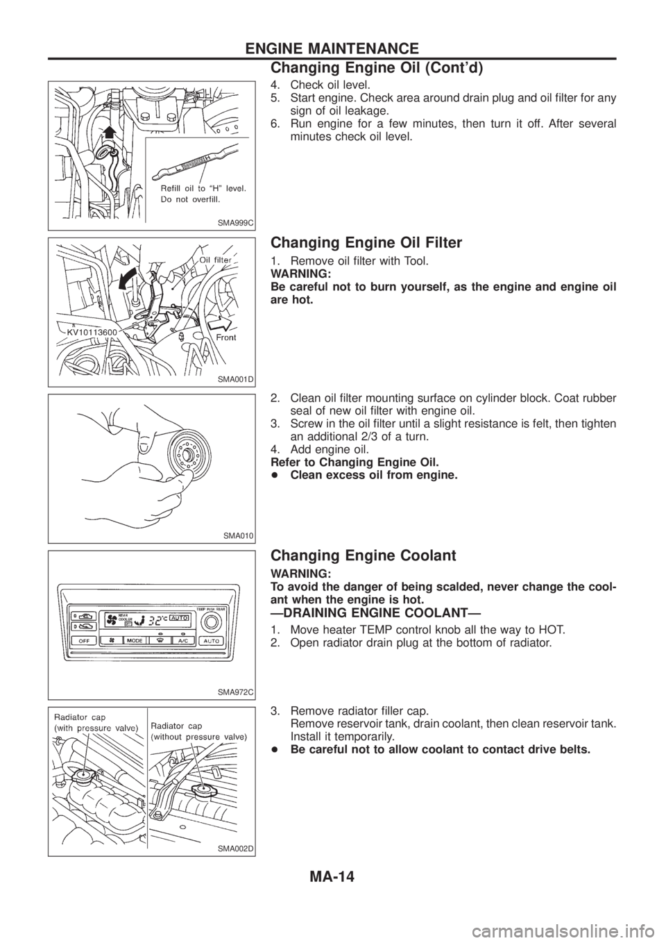
4. Check oil level.
5. Start engine. Check area around drain plug and oil ®lter for any
sign of oil leakage.
6. Run engine for a few minutes, then turn it off. After several
minutes check oil level.
Changing Engine Oil Filter
1. Remove oil ®lter with Tool.
WARNING:
Be careful not to burn yourself, as the engine and engine oil
are hot.
2. Clean oil ®lter mounting surface on cylinder block. Coat rubber
seal of new oil ®lter with engine oil.
3. Screw in the oil ®lter until a slight resistance is felt, then tighten
an additional 2/3 of a turn.
4. Add engine oil.
Refer to Changing Engine Oil.
+Clean excess oil from engine.
Changing Engine Coolant
WARNING:
To avoid the danger of being scalded, never change the cool-
ant when the engine is hot.
ÐDRAINING ENGINE COOLANTÐ
1. Move heater TEMP control knob all the way to HOT.
2. Open radiator drain plug at the bottom of radiator.
3. Remove radiator ®ller cap.
Remove reservoir tank, drain coolant, then clean reservoir tank.
Install it temporarily.
+Be careful not to allow coolant to contact drive belts.
SMA999C
SMA001D
SMA010
SMA972C
SMA002D
ENGINE MAINTENANCE
Changing Engine Oil (Cont'd)
MA-14
Page 992 of 1226
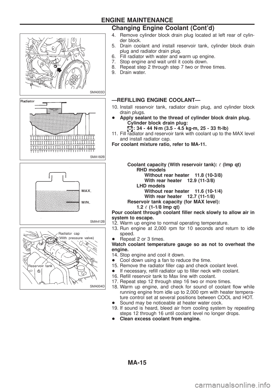
4. Remove cylinder block drain plug located at left rear of cylin-
der block.
5. Drain coolant and install reservoir tank, cylinder block drain
plug and radiator drain plug.
6. Fill radiator with water and warm up engine.
7. Stop engine and wait until it cools down.
8. Repeat step 2 through step 7 two or three times.
9. Drain water.
ÐREFILLING ENGINE COOLANTÐ
10. Install reservoir tank, radiator drain plug, and cylinder block
drain plugs.
+Apply sealant to the thread of cylinder block drain plug.
Cylinder block drain plug:
:34-44Nzm (3.5 - 4.5 kg-m, 25 - 33 ft-lb)
11. Fill radiator and reservoir tank with coolant up to the MAX level
and install radiator cap.
For coolant mixture ratio, refer to MA-11.
Coolant capacity (With reservoir tank):!(Imp qt)
RHD models
Without rear heater 11.8 (10-3/8)
With rear heater 12.9 (11-3/8)
LHD models
Without rear heater 11.6 (10-1/4)
With rear heater 12.7 (11-1/8)
Reservoir tank capacity (for MAX level):
1.2!(1-1/8 Imp qt)
Pour coolant through coolant ®ller neck slowly to allow air in
system to escape.
12. Warm up engine to normal operating temperature.
13. Run engine at 2,000 rpm for 10 seconds and return to idle
speed.
+Repeat 2 or 3 times.
Watch coolant temperature gauge so as not to overheat the
engine.
14. Stop engine and cool it down.
+Cool down using a fan to reduce the time.
15. Remove the radiator ®ller cap and check coolant level.
+If necessary, re®ll radiator up to ®ller neck with coolant.
16. Re®ll reservoir tank to Max line with coolant.
17. Repeat step 12 through step 16 two or more times.
18. Warm up engine, and check for sound of coolant ¯ow while
running engine from idle up to 2,000 rpm with heater tempera-
ture control set at several positions between COOL and HOT.
+Sound may be noticeable at heater water cock.
19. If sound is heard, bleed air from cooling system by repeating
steps 12 through 16 until coolant level no longer drops.
+Clean excess coolant from engine.
SMA003D
SMA182B
SMA412B
SMA004D
ENGINE MAINTENANCE
Changing Engine Coolant (Cont'd)
MA-15
Page 994 of 1226
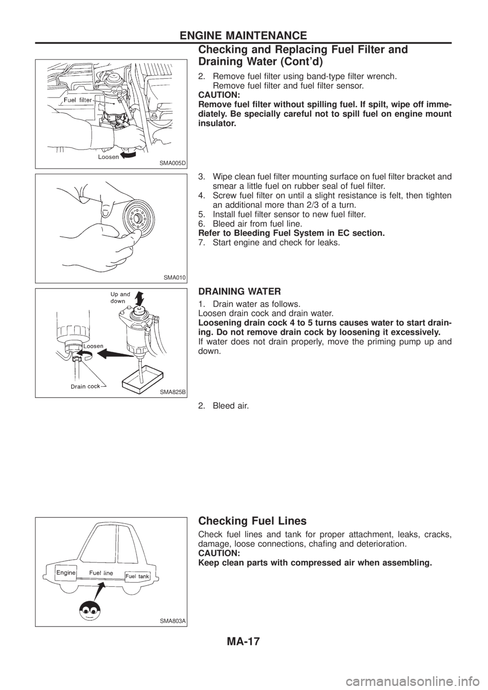
2. Remove fuel ®lter using band-type ®lter wrench.
Remove fuel ®lter and fuel ®lter sensor.
CAUTION:
Remove fuel ®lter without spilling fuel. If spilt, wipe off imme-
diately. Be specially careful not to spill fuel on engine mount
insulator.
3. Wipe clean fuel ®lter mounting surface on fuel ®lter bracket and
smear a little fuel on rubber seal of fuel ®lter.
4. Screw fuel ®lter on until a slight resistance is felt, then tighten
an additional more than 2/3 of a turn.
5. Install fuel ®lter sensor to new fuel ®lter.
6. Bleed air from fuel line.
Refer to Bleeding Fuel System in EC section.
7. Start engine and check for leaks.
DRAINING WATER
1. Drain water as follows.
Loosen drain cock and drain water.
Loosening drain cock 4 to 5 turns causes water to start drain-
ing. Do not remove drain cock by loosening it excessively.
If water does not drain properly, move the priming pump up and
down.
2. Bleed air.
Checking Fuel Lines
Check fuel lines and tank for proper attachment, leaks, cracks,
damage, loose connections, cha®ng and deterioration.
CAUTION:
Keep clean parts with compressed air when assembling.
SMA005D
SMA010
SMA825B
SMA803A
ENGINE MAINTENANCE
Checking and Replacing Fuel Filter and
Draining Water (Cont'd)
MA-17
Page 1006 of 1226
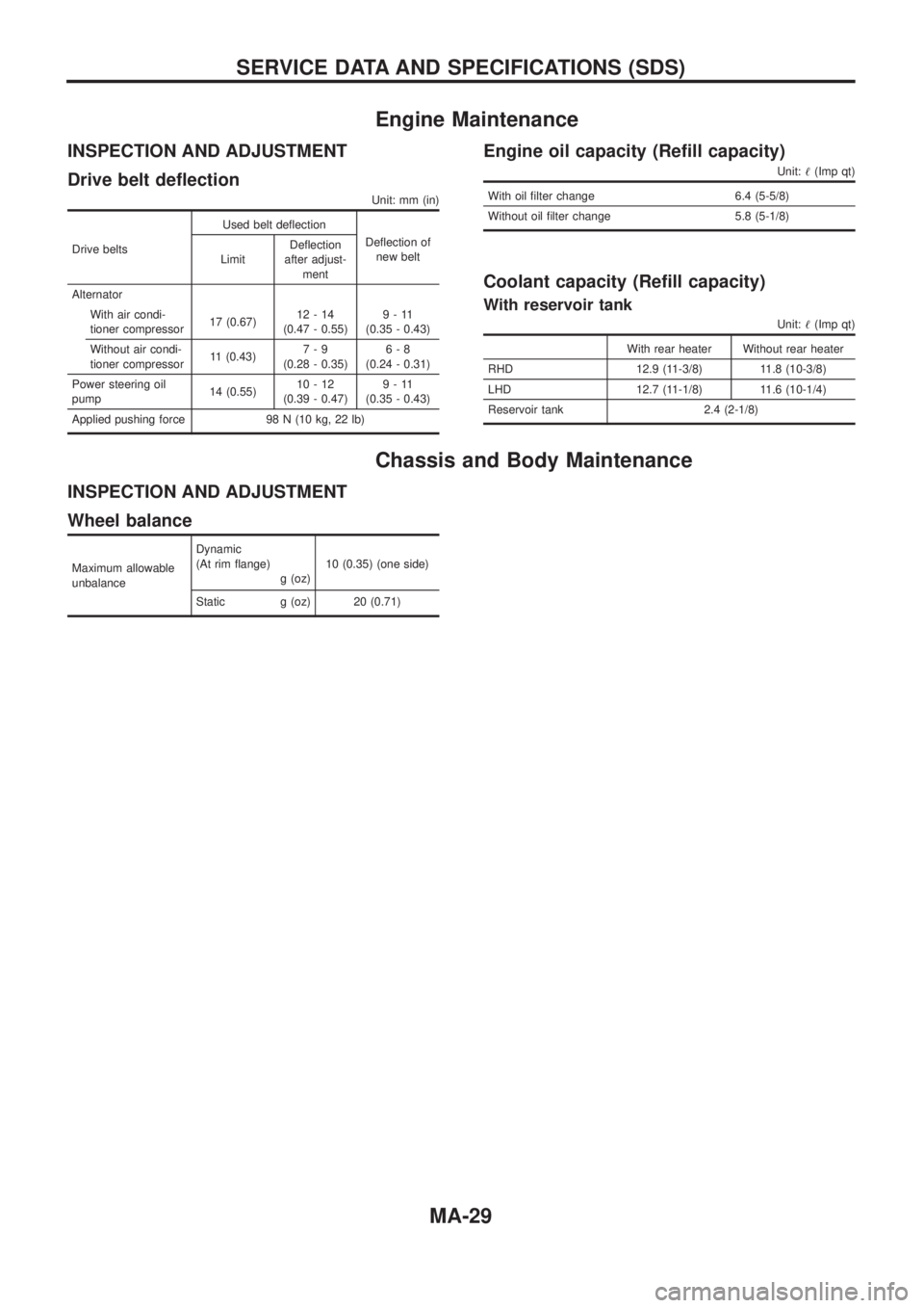
Engine Maintenance
INSPECTION AND ADJUSTMENT
Drive belt de¯ection
Unit: mm (in)
Drive beltsUsed belt de¯ection
De¯ection of
new belt
LimitDe¯ection
after adjust-
ment
Alternator
With air condi-
tioner compressor17 (0.67)12-14
(0.47 - 0.55)9-11
(0.35 - 0.43)
Without air condi-
tioner compressor11 (0.43)7-9
(0.28 - 0.35)6-8
(0.24 - 0.31)
Power steering oil
pump14 (0.55)10-12
(0.39 - 0.47)9-11
(0.35 - 0.43)
Applied pushing force 98 N (10 kg, 22 lb)
Engine oil capacity (Re®ll capacity)
Unit:!(Imp qt)
With oil ®lter change 6.4 (5-5/8)
Without oil ®lter change 5.8 (5-1/8)
Coolant capacity (Re®ll capacity)
With reservoir tank
Unit:!(Imp qt)
With rear heater Without rear heater
RHD 12.9 (11-3/8) 11.8 (10-3/8)
LHD 12.7 (11-1/8) 11.6 (10-1/4)
Reservoir tank 2.4 (2-1/8)
Chassis and Body Maintenance
INSPECTION AND ADJUSTMENT
Wheel balance
Maximum allowable
unbalanceDynamic
(At rim ¯ange)
g (oz)10 (0.35) (one side)
Static g (oz) 20 (0.71)
SERVICE DATA AND SPECIFICATIONS (SDS)
MA-29